CNC Milling Tolerances Explained: How Precision Requirements Impact Cost and Manufacturability
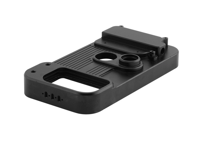
CNC milling tolerances affect cost and manufacturability because every tighter requirement reduces the process window for tool deflection, fixturing, heat, material movement, setup transfer, and inspection. In CNC milling, tolerance is therefore a manufacturing and purchasing decision, not only a number on a drawing. General tolerances are efficient for many custom parts, while critical holes, datums, sealing surfaces, bearing fits, and mating geometry may need controlled precision. Buyers should separate functional precision from default precision before RFQ release, then define datums, material condition, surface finish, and inspection expectations. These inputs let the supplier separate ordinary size control from features that require a controlled precision route.
For product designers and OEM buyers, the key challenge is deciding which dimensions protect function and which dimensions only add cost. A part may contain dozens of dimensions, but only a few usually control assembly, motion, sealing, alignment, or performance. If every dimension is specified tightly, cost rises without improving the product. If critical relationships are under-specified, the part may be cheaper but unreliable in use. Good tolerance planning identifies where true precision is needed and where standard manufacturable tolerance is sufficient. This principle is closely related to balancing precision, functionality, and cost in CNC machining.
What CNC Milling Tolerances Actually Mean
A CNC milling tolerance defines allowable variation from a nominal dimension, location, orientation, or geometric condition. Linear tolerances control widths, thicknesses, lengths, slot sizes, and hole diameters. Geometric controls such as flatness, perpendicularity, position, concentricity, and profile define relationships between surfaces and features. Surface roughness can also act as a precision requirement when sealing, sliding, bonding, or cosmetic function depends on controlled texture.
Tolerance is broader than dimensional size alone. A milled part may meet length and width requirements but fail because a hole position is off relative to a datum face, or because a sealing surface is not flat enough for assembly. Tolerance review must therefore consider dimensional values, GD&T relationships, measurement method, and how the part functions in the final product. The acceptance rule should match how the part will be measured, not only how the CAD model looks. The basics of this review are strongly aligned with standard CNC machining tolerance and the difference between dimensional and geometric tolerances.
Why Tighter CNC Milling Tolerances Increase Cost
Tighter CNC milling tolerances increase cost because they reduce process freedom. When tolerance bands allow standard machining practice, programmers can use efficient toolpaths, normal material removal rates, and conventional inspection frequency. As tolerance narrows, every source of variation matters more. Tool wear, material stress release, spindle growth, machine vibration, fixture distortion, coolant performance, and temperature change can all move a feature. The process must be slowed, stabilized, measured, and corrected more often. Measurement uncertainty also becomes part of the decision because a feature cannot be accepted confidently if the inspection method is too coarse.
This usually means longer cycle times, more tool changes, more careful setup alignment, and greater inspection effort. On complex custom parts, the supplier may also need roughing with stock allowance, stress-relief pause, semi-finishing, rest machining, spring passes, or selective post-machining after initial probing. Scrap risk increases because a smaller error can cause rejection. In commercial terms, the buyer pays for the control plan required to deliver precision repeatedly. This cost relationship is also reflected in how tighter tolerances impact CNC machining costs and why tight tolerances increase CNC milling costs.
Main Cost Drivers Created by Tight Tolerances
Cost Driver | Why It Increases | Manufacturing Effect | Commercial Result |
|---|---|---|---|
Cycle time | Slower feeds and more finishing passes | Longer spindle occupancy | Higher part cost |
Inspection | More measurement points and reports | Greater QA workload | Higher overhead per lot |
Setup control | More precise fixturing and alignment | Longer preparation time | Higher setup charge |
Tooling | More stable and wear-controlled cutting tools | Frequent offsets or tool replacement | Higher consumable cost |
Scrap risk | Smaller allowable deviation band | More rejected parts or rework | Higher risk premium |
How Tolerance Requirements Affect Manufacturability
Tolerance requirements affect manufacturability by deciding how sensitive a design is to normal process variation. A part with reasonable wall thickness, accessible datums, simple tool access, and function-based tolerance zones is usually easier to produce repeatedly. A part with deep thin pockets, unstable clamping surfaces, long narrow slots, tight position requirements across multiple faces, and universal tight dimensions is much harder to machine economically. The same nominal tolerance can be easy on an open external face and risky inside a deep pocket or flexible wall.
Manufacturability worsens when the drawing forces unnecessary setups, asks hard-to-reach features to hold tight relationships, or applies the same precision expectation to non-functional dimensions and critical interfaces. Even if the part is technically machinable, the route may become slow, fragile, or difficult to scale. The most efficient programs align tolerance zones with product function and stable datums. RFQs should therefore show critical features, acceptable standard tolerance areas, material condition, and inspection expectations. This logic connects directly to DFM for CNC machining and how to optimize part design for CNC manufacturability.
Standard vs Tight Tolerances in CNC Milling
Most custom milled parts do not need ultra-tight tolerance across every feature. Standard tolerances are appropriate for many non-critical dimensions, cosmetic edges, clearance features, covers, brackets, and general housings. Tight tolerances should be reserved for dimensions that influence assembly fit, bearing support, motion, sealing, load path alignment, or functional interface relationships. Applying tight tolerance only where needed preserves both quality and cost efficiency.
A useful rule is that the tighter the required relationship between features, the more carefully the process must be designed around datums, tool access, thermal behavior, and inspection references. A flat mounting surface may need moderate control, while a bearing bore aligned to a sealing face may need tighter control and a documented inspection method. Engineers should assign tolerance according to feature function rather than drawing habit. This kind of prioritization is supported by how to identify dimensions that require tight tolerances.
Standard and Critical Feature Tolerance Logic
Feature Type | Typical Tolerance Priority | Why It Matters | Design Recommendation |
|---|---|---|---|
Overall outer profile | Moderate | Usually not assembly-critical | Use standard manufacturable tolerance |
Mounting hole pattern | High | Affects part alignment during assembly | Reference to stable datum surfaces |
Bearing or sealing bore | Very high | Controls fit, leakage, or motion accuracy | Tighten only this critical zone |
Cosmetic non-mating edges | Low to moderate | Little effect on function | Avoid unnecessary precision callout |
Datum surfaces | High | Control all related downstream features | Define clearly and machine accessibly |
How Fixturing and Setup Count Influence Tolerance Capability
Fixturing and setup count strongly influence CNC milling tolerance capability because every repositioning step can introduce datum shift, angular deviation, local distortion, or reference mismatch. A part machined in one stable setup usually holds critical inter-feature relationships more consistently than a part that requires several setup transfers. That is why process planning and tolerance planning must be linked before the quote is finalized.
Workholding also matters because clamping can distort thin walls, flexible parts, soft metals, or plastics if force is poorly distributed. Tight-tolerance fixtures often need to be designed around datum logic, contact stability, and deflection control. A stable fixture can sometimes solve a tolerance problem that would otherwise look like a machine capability issue. In some cases, changing part orientation or using a higher-axis route reduces tolerance stack-up more effectively than tightening the drawing again. This is one reason advanced setups are often evaluated alongside 3-axis, 4-axis, and 5-axis CNC milling selection.
The Role of Material in CNC Milling Tolerance Control
Material choice changes how easy it is to hold a given tolerance. Aluminum is generally easier to mill quickly, but thin sections can move after material removal, especially on large plate-like parts. Stainless steel may generate more heat and cutting force, which can affect tool wear and dimensional drift. Engineering plastics can be challenging because thermal expansion, low stiffness, and stress relief may change feature size after machining. Harder materials may offer better rigidity in service but require slower cutting and stronger process control.
A tolerance that is practical in one material may be expensive or unstable in another. Designers should avoid assigning identical expectations to aluminum, stainless steel, titanium, and plastic without considering how each behaves under cutting load, clamping force, and ambient temperature change. The RFQ should specify grade, temper or heat treatment, stock form, and any post-machining finish that can affect final size. Material-aware tolerance planning is tied closely to tolerance differences between metal and plastic CNC parts and tolerance and warping considerations in plastic CNC milling.
Surface Finish and Tolerance Are Often Linked
Tolerance and surface finish are specified separately on drawings, but in real milling they interact closely. A fine surface finish may require lighter finishing passes, sharper tools, lower feed marks, improved vibration control, and more stable thermal conditions. On sealing or sliding surfaces, finish can be as important as size tolerance because it affects leakage, wear, friction, or appearance. Polishing, grinding, coating, or other surface steps can also change the final dimension if allowance is not planned.
Finish specifications should be reviewed together with dimension control instead of being added independently. An unnecessarily fine finish on a non-functional face can raise cost without benefit, while an under-specified finish on a sealing face can cause assembly failure even if size is correct. Drawings should state where finish is functional, which surfaces are cosmetic, and whether inspection should verify roughness or only dimension. This relationship is also supported by how surface roughness is measured and specified and how tolerances, surface finish, and geometry are verified in CNC machining.
How Inspection Requirements Grow with Precision Demands
As precision requirements increase, inspection requirements grow accordingly. A general bracket may need basic dimensional checks using calipers or gauges. A precision milled component with positional tolerance, profile control, or tight geometric relationships may require coordinate-based inspection, scanning, or full report documentation. Precision cost therefore includes the time and equipment needed to prove conformance, not only machining time.
For critical custom parts, inspection may involve structured feature measurement, first article validation, report traceability, and sampling plans designed around process stability. This is especially important where dimensional verification is part of customer approval or regulated documentation. Buyers should state which features need records, which can be checked routinely, and whether FAIR or CMM documentation is expected. Relevant quality routes include inspection tools for verifying tight tolerances, ISO-certified CMM quality assurance, and full CMM inspection reports and FAIR documentation.
Inspection Strategy by Precision Level
Precision Level | Typical Inspection Method | Production Effect | Cost Impact |
|---|---|---|---|
General tolerance | Basic manual measurement | Fast release and low overhead | Low |
Moderate critical features | Height gauge, bore gauge, fixture-based checks | More controlled validation | Moderate |
High precision geometry | CMM or advanced coordinate inspection | Higher QA time and traceability | High |
Complex contour or profile | Scanning or contour analysis | Detailed feature confirmation | High to very high |
Common Design Mistakes That Make Tight-Tolerance Parts Expensive
Many tolerance-related cost problems come from drawing strategy rather than product function. One mistake is over-tolerancing all dimensions by default instead of focusing on critical interfaces. Another is applying tight positional control to features that are not referenced from practical datums. Thin walls, deep pockets, long unsupported features, narrow ribs, and hard-to-access bores can also force expensive process changes when combined with tight precision requirements. Stacked geometric relationships across multiple faces can add cost if setup strategy is not considered. A feature may look simple in CAD but become costly when measurement access or datum transfer is poor.
A more effective approach is to simplify datum structure, reduce tolerance chains, and isolate high precision to functional zones. Features that do not affect assembly or performance should usually follow standard CNC milling capability. This prevents the entire part from being priced like a precision instrument when only a few interfaces need that level of control. This issue is aligned with common design mistakes that increase CNC part cost.
How to Optimize CNC Milling Tolerances Without Risking Part Function
Tolerance optimization means assigning the loosest tolerance that still protects product function. This does not reduce quality. It makes the manufacturing requirement proportional to assembly needs. The best method is to classify features into functional and non-functional groups, define stable datums early, and review where location, flatness, bore size, or perpendicularity truly affects performance. Where necessary, selective post-machining can be used for a few critical surfaces while the rest of the part remains at standard capability.
This approach is valuable in prototype-to-production transitions. Early prototypes often carry unnecessary universal precision because the design team is cautious. Once function is validated, tolerance can be redistributed around actual risk points. Supplier feedback is important at this stage because process route, material behavior, inspection method, and batch volume can change the best tolerance plan. This design logic is closely tied to tolerance review during quoting and the role of tolerance optimization in product design.
Industry Examples Where Tolerance Planning Matters Most
Industry | Typical Critical Features | Why Precision Matters | Manufacturing Focus |
|---|---|---|---|
Bores, mating faces, mini interfaces | Assembly reliability and functional safety | High inspection control and surface quality | |
Datums, profile features, multi-face alignment | Performance, traceability, system fit | Strong datum strategy and advanced QA | |
Mounting patterns, guide surfaces, actuator fits | Repeatability and assembly speed | Selective precision where motion depends on it | |
Sealing faces, shaft seats, flange geometry | Durability and service performance | Balance between cost and rugged functionality | |
Hole position, interface flatness, repeatable fits | Batch consistency and assembly efficiency | Process capability and sampling discipline |
How Neway Manages CNC Milling Tolerance Requirements
For Neway CNC milling tolerance review, the useful starting point is feature function rather than the tightest number on the drawing. Engineering review should focus on datum structure, material behavior, setup strategy, critical surfaces, and whether the required precision can be held economically in production. The RFQ is clearer when it separates must-hold features from areas where standard tolerance is acceptable. This helps separate features that can use standard process capability from features that need tighter control, additional inspection, or alternative routing.
This tolerance-driven review connects with broader services in Precision Machining, CNC Machining, and One Stop Service. When tolerance requirements are matched to actual function and manufacturing logic, custom milled parts can achieve the needed quality level without carrying unnecessary cost across the entire design.
Conclusion: CNC Milling Tolerances Should Protect Function, Not Inflate Cost
CNC milling tolerances should protect product function without inflating cost. Tight precision increases cycle time, setup complexity, tooling control, inspection depth, and rejection risk. The highest-value drawings identify critical features, define sensible datums, separate size tolerance from GD&T and surface finish, and apply tighter requirements only where assembly, sealing, motion, or performance depends on them. For an RFQ, send the 3D model, 2D drawing, material condition, functional dimensions, datum scheme, finish targets, and inspection expectations so the supplier can build a manufacturing route around real risk instead of blanket precision. That preparation improves price accuracy and reduces late redesign, inspection disputes, and preventable tolerance-driven delays.
FAQs