PDCA Quality System for High-Precision CNC Machining
A PDCA quality system supports high-precision CNC machining by connecting CTQ planning, controlled production, measurement review, and corrective-action standardization in a repeatable loop. It is useful when functional features must remain stable from prototype and pilot lots into repeat production. PDCA does not replace drawing tolerances, inspection plans, capable measurement systems, or operator skill. It organizes those controls: define the risk and variables, run the approved process, evaluate objective evidence, and preserve a verified correction in future work. Buyers should judge the system by its records and reaction logic. Before placing an order, request the critical features, process variables, gauge plan, reaction rules, and release evidence. Missing links can produce one acceptable lot without a defensible route for repeating it. The RFQ should include drawings, material condition, CTQ notes, volume profile, inspection expectations, and known assembly risks.

Why PDCA Matters in Precision CNC Shops
Tolerances, stability, and repeatability
Parts can move out of tolerance through small, ordinary changes: tool wear, fixture settling, coolant concentration, datum shift, and shop temperature. PDCA requires the supplier to identify CTQ features before machining and then control the variables that move those features. Prismatic faces and pockets often depend on stable CNC milling capability. Round datums and shafts may require controlled turning processes. Thin webs, sharp internal corners, or hard conductive materials may need EDM work. When a part crosses several processes, an integrated CNC machining service should define ownership for each datum, inspection step, and release decision.
Working to industry expectations
When an aerospace or medical contract requires traceability, measurement-system discipline, first-article evidence, or controlled change records, PDCA can connect those obligations to the production route. It does not make one inspection report evidence of long-term capability. For aerospace and aviation or medical devices, buyers should ask how the supplier connects contract CTQs, MSA, FAI, SPC, nonconformance records, and approved training updates. The answer should show who controls each requirement from quote review through shipment.
Practical wins
The practical buyer benefit is risk control. When CTQs are built into the control plan and monitored with SPC, first articles can be reviewed with clearer evidence. Rework decisions become traceable, and cost shifts from emergency sorting toward prevention. The improvement is conditional: the gauges must be capable, operators must follow reaction rules, and corrective actions must survive the next lot. PDCA also improves communication during quoting. The buyer can ask for the planned inspection route, sample frequency, capability review point, and nonconformance response. The supplier can then price the real controls instead of hiding quality cost inside late sorting, rework, or emergency expediting.
PLAN — How a Robust Quality Plan Is Built
Voice of Customer and CTQs
Planning starts with the print, 3D model, material callout, assembly function, and inspection requirement. Features that seal, locate, carry load, align another part, or control motion become CTQs. The plan should define datum order, feature access, inspection temperature, fixture concept, and the difference between process control and final acceptance. If a tolerance depends on an unproven setup, a controlled prototyping process can test workholding, tool reach, burr behavior, and measurement method before production routing is frozen.
Flow, control plan, and inspection plan
Each operation should list the machine type, workholding, cutting tools, program revision, coolant condition, material state, inspection method, sample frequency, and reaction plan. A control plan should also say what happens when a trend moves toward the limit. CTQ gauges need GR&R or another appropriate measurement-system review. Without measurement capability, SPC may only chart gauge noise rather than real process variation.
DFM and fixturing
DFM should be tied to measurable risk, not only cycle time. Milled parts need stable datums, accessible features, and controlled re-clamping. Turned parts may need soft-jaw strategy, jaw boring, and runout checks. Fragile webs or heat-resistant materials may require EDM for high-risk features. If a part needs several orientations, a single-setup multi-axis approach can reduce datum transfer error when the fixture, probing plan, and inspection method support that route.
Risk management and traceability
PFMEA should identify failures before the first production lot: datum mismatch, burr at a sealing edge, heat distortion, wrong revision, tool-life overrun, or gauge misuse. High-risk items need error-proofing, enhanced checks, or a different route. Traceability should tie heat lot, machine ID, program revision, operator signoff, inspection record, and rework decision to each batch or serial number. This lets the supplier answer “what changed?” with evidence. Buyers should ask how split lots, outsourced finishing, reinspection, and deviation approvals stay connected to the same genealogy. A beautiful final report has limited value if it cannot identify which parts share the same suspect condition.
Materials and downstream processes
Material behavior changes the PDCA plan. Aluminum 6061-T6 is often selected when moderate strength, machinability, and cost balance are important. Ti-6Al-4V (TC4) can fit high specific-strength applications, but heat, tool wear, and residual stress require closer review. Inconel 718 may suit hot or high-load environments, yet work hardening and cutting heat affect tool-life windows. SUS316L can support corrosion-critical housings when passivation, burr control, and surface finish are planned together.
Metrology that fits the print
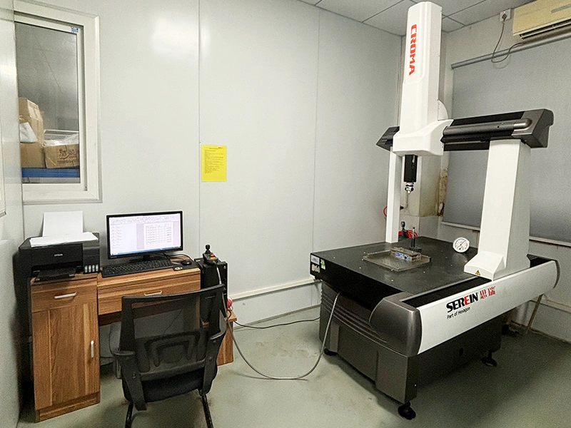
Metrology should fit the print and the failure risk. Datum features and positional tolerances often need tactile CMM or hard gauging. Small slots, chamfers, and edge breaks may need optical checks. Surface roughness claims require profilometry with a defined cutoff and direction. Threads need go/no-go or dedicated thread gauges. Sampling should follow feature risk, lot size, and process stability. The inspection plan should also state acceptance conditions, such as part temperature, cleaning state, coating state, and datum setup. A mismatch between machining datum and inspection datum can create a false dispute even when both parties measure carefully.
DO — How Stable Production Is Run
Program verification and first article
The Do phase turns the plan into controlled production evidence. Posts, kinematics, fixtures, tool offsets, and probing routines should be verified before cutting production material. Dry runs and safe approach moves reduce collision risk. First articles should be production-representative, not special samples made outside the approved route. Their results support route and inspection review under the stated conditions; they do not establish capability for every future lot.
Setups, probing, and temperature
Stable production depends on repeatable setup behavior. Torque values, tool-length offsets, clamping sequence, and locator cleanliness should be controlled. Probe routines can confirm fixture position and key features during the cycle, but probing does not replace final acceptance. Warm-up cycles, coolant concentration, and room temperature help reduce thermal drift. For very tight features, a dedicated precision machining setup should define the machine state, inspection method, and allowed offset rule.
Launch capability
Launch capability should be proven before volume approval. A pilot lot can measure Cp or Cpk on CTQs when the process is stable and the measurement method is capable. If a feature wanders, the reaction may involve cutter geometry, feed strategy, fixture support, stock allowance, inspection method, or a separate EDM finishing stage. The decision should be documented before the next lot begins.
Controlling changes
Change control is where many quality systems leak. An ECN should update the traveler, CNC program, tool list, fixture note, inspection plan, and revision record together. If the change touches a CTQ, capability and measurement evidence should be reviewed again. Buyers should ask whether pre-change parts, WIP parts, and post-change parts are separated in the traceability record.
Managing special processes
Heat treatment and coatings should be planned as part of the route, not added after machining is finished. For aluminum housings, anodizing for corrosion resistance can change surface thickness and affect threaded or close-fit features. For stainless flow components, electropolishing may improve smoothness when bore size and edge condition are verified after processing. chemical passivation supports corrosion resistance when material, cleaning, and acceptance method are specified.
CHECK — What Should Be Measured and Reviewed
In-process and final inspections; GR&R
In-process checks protect cycle time, while final checks support shipment decisions. Probe hits, go/no-go gauges, and visual controls can catch drift early. CMM audits verify geometry when datum and feature strategy match the drawing. Any gauge used for a CTQ should have current GR&R or equivalent measurement-system evidence, so gauge variation does not hide part variation. The Check phase should compare the actual data with the control plan, not with memory. If a bore trend moves after tool change, the reaction may be a tool-life rule. If the trend moves after unclamping, the reaction may be fixture support or a revised operation sequence.
SPC that actually gets used
SPC should be used only when the charted characteristic, sampling frequency, and reaction rule are defined. A useful chart shows whether the process is stable, drifting, or outside control. The reaction plan should state who can adjust offsets, when the lot stops, and how suspect parts are segregated. Waiting for final rejection defeats the purpose of PDCA.
FAIs and periodic audits
FAI documents whether the initial item follows the approved route and meets the specified inspection requirements under recorded conditions. It does not prove that every future lot will conform or that the process is statistically capable. Periodic audits should check fixture wear, program revision, datum discipline, gauge health, and operator adherence according to product risk and contract requirements. Audit findings should enter the applicable correction or Act workflow instead of remaining isolated comments.
Nonconformance and root cause
When a nonconformance appears, the record should capture operation, machine, tool, gauge, operator, time, program revision, and material lot. That context separates a one-part anomaly from a process pattern. 5-Why, fishbone, and 8D can help, but the method only works when the corrective action controls the real variable and includes recurrence review.
ACT — How Corrective Actions Become Standard Work
Standardizing what works
A corrective action becomes standard work only when the controlled documents and shop-floor behavior change together. Work instructions, fixture drawings, CNC macros, probe logic, training records, and visual controls may all need revision. Old revisions should be archived with traceability, and WIP should be checked against the correct revision before release.
Error-proofing and adaptive control
Error-proofing can be physical, such as keyed fixtures or dedicated gauges. It can also be digital, such as macros that stop a cycle when probing finds drift. Adaptive offsets may help on abrasive alloys, but the offset rule needs limits and approval. Otherwise, automatic correction can mask tool wear or fixture movement.
Kaizen with ROI
Kaizen should be ranked by CTQ risk, scrap risk, inspection burden, and financial impact. A single-setup multi-axis strategy can be valuable when it removes re-clamping and datum stack-up. It is not automatically better. The fixture, tool reach, programming risk, and inspection method still need review before the route changes.
Capturing the lesson
The lesson record should explain what changed, why the change worked, where it applies, and where it does not apply. This boundary prevents a good fix from being copied to the wrong material or geometry. The next similar part family can start with better controls, but it still needs its own CTQ and measurement review.
Three Representative PDCA Engineering Scenarios
1) Aerospace bracket (6061-T6)
Representative scenario: a 6061-T6 aerospace bracket has a positional tolerance tied to two datums. Re-clamping can shift the datum relationship and make a good toolpath look unstable. A PDCA response would plan a single-setup trunnion route, probe datums in-cycle, verify true position on a production-representative FAI, and standardize the offset rule only after the pilot data supports it. The buyer decision is whether the added setup control is worth the cost compared with looser nonfunctional tolerances.
2) Medical housing (SUS316L)
Representative scenario: a SUS316L medical housing has internal Ra limits, burr limits, and threaded interfaces. The Plan step should define burr acceptance, profilometer method, thread gauge, cleaning sequence, and electropolishing boundary. The Do step should avoid uncontrolled hand deburring that changes bore size. The Check step should connect CMM, profilometry, and visual inspection to the same serial or lot record. The Act step should standardize only the proven deburring and finishing conditions.
3) Turbine test fixture (Inconel 718)
Representative scenario: an Inconel 718 turbine test fixture includes a thin web near interrupted cuts. The risk is not only cutter wear. Heat, work hardening, clamp force, and stress relief can move the web after roughing. A PDCA route may rough the feature, stabilize the part, finish the web by EDM, and inspect after thermal equalization. The standardized rule should apply only to similar nickel-alloy geometries with comparable wall thickness and datum access.
The infrastructure that makes this possible
The infrastructure behind PDCA combines machines, inspection systems, people, authority, and controlled records. Multi-axis machines can reduce re-clamping. Probing can locate datums and detect drift, while tool management can prevent unplanned use beyond an approved life. Condition monitoring can flag spindle, axis, or thermal changes that require review. A digital QMS can connect drawings, travelers, SPC, MSA, FAI, NCRs, and corrective actions, but software does not repair incomplete ownership. For features specified in single-digit micrometers, buyers should confirm the geometry, material state, machine condition, gauge capability, thermal condition, and release method instead of accepting a general precision claim. Someone must own offset changes, lot holds, gauge quarantine, customer notification, and document revision. Without that authority, PDCA becomes a meeting cycle rather than a production control system.
What PDCA changes in cost and lead time
PDCA can improve cost and lead time when prevention reduces rework, sorting, and late engineering changes. The learning curve should move from prototype evidence to pilot-lot capability and then to production stability. A buyer can stage risk through low-volume manufacturing paths before moving to mass production. The transition should wait until CTQ capability, measurement-system evidence, operator reaction rules, and change-control records are acceptable. PDCA also helps decide where cost should be spent. Functional datums, sealing surfaces, bearing fits, and safety-related holes may deserve tighter controls. Cosmetic surfaces or nonfunctional clearances may be better handled with practical tolerances and simpler inspection. That distinction prevents buyers from paying for precision that does not reduce product risk. The RFQ should label which tolerances are functional before supplier quoting.
A 30-Day PDCA Starter Playbook for Buyers
This 30-day sequence is an illustrative review cadence, not a universal production or delivery commitment; complex qualification, destructive testing, or customer approval can require a different schedule. Week 1 maps CTQs, confirms datums, drafts the control plan, selects gauges, defines sampling, and assigns reaction rules. Week 2 runs a production-representative pilot, reviews MSA or GR&R for CTQ gauges, and begins suitable SPC monitoring. Week 3 audits the cell, traveler, program revision, gauge status, traceability, and containment method. Week 4 reviews capability evidence, NCRs, cycle time, rework, and inspection burden before standard work is released. The buyer can use the sequence as an RFQ evidence list: CTQs, control plan, gauge plan, pilot results, SPC reaction rule, traceability method, and corrective-action closure format. Suppliers may redact private records, but the decision path should remain clear enough for technical review.
FAQs