English
Custom Parts Manufacturing Solutions
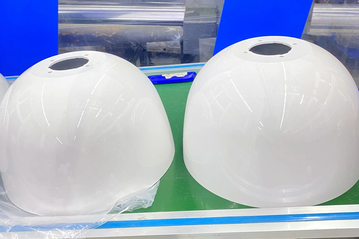
Automotive Components Manufacturing Service
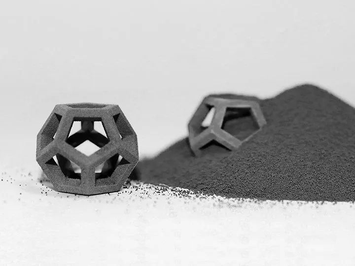
Neway provides Automotive Components Manufacturing, offering CNC Machining, 3D Printing, Vacuum Casting, Die Casting, and Injection Molding. We deliver high-quality, precision-engineered parts to meet the rigorous standards of the automotive industry.
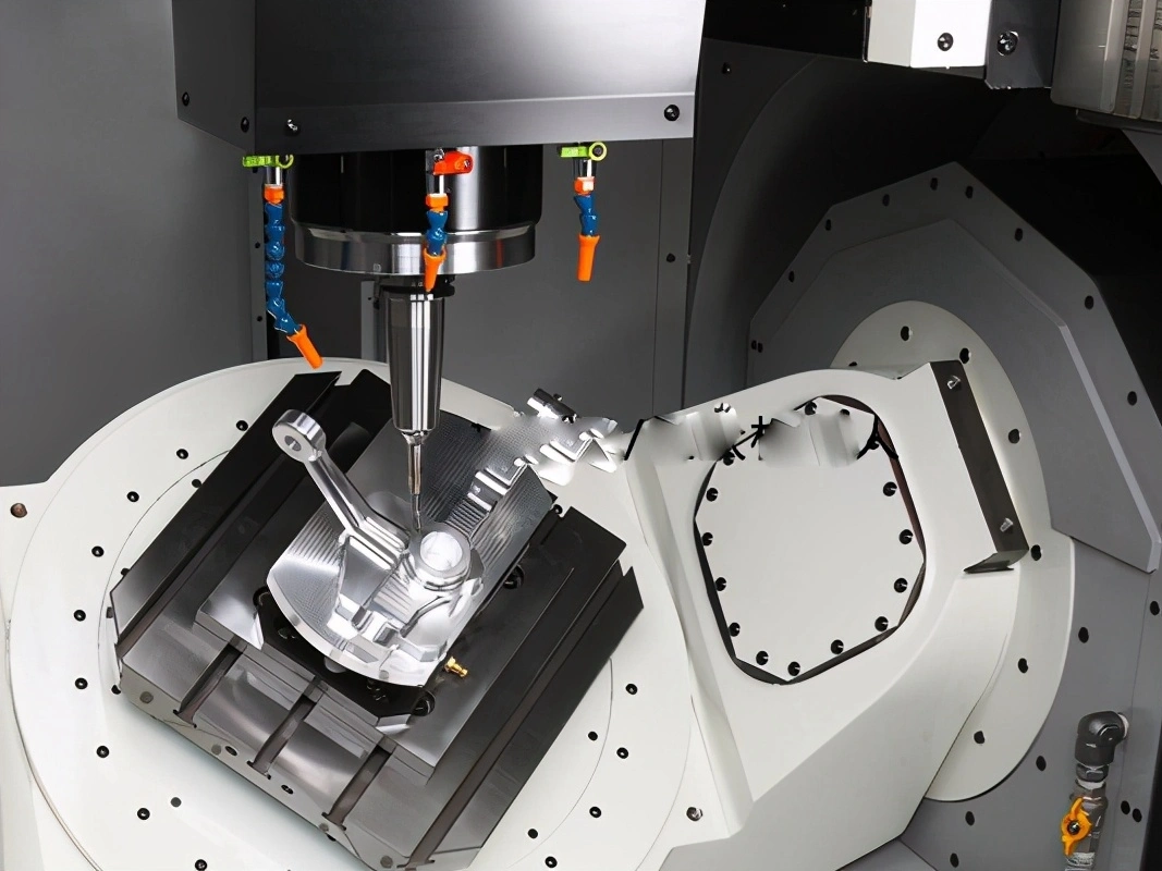
Custom Automotive Parts Machining
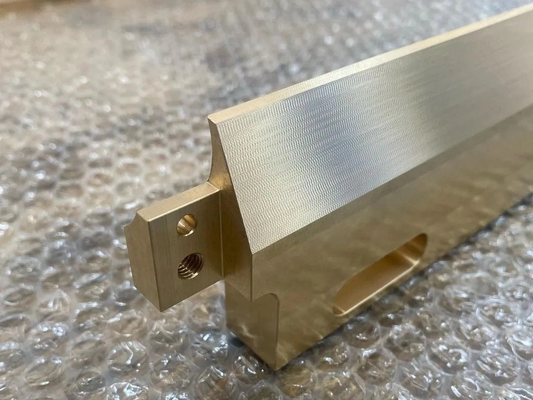
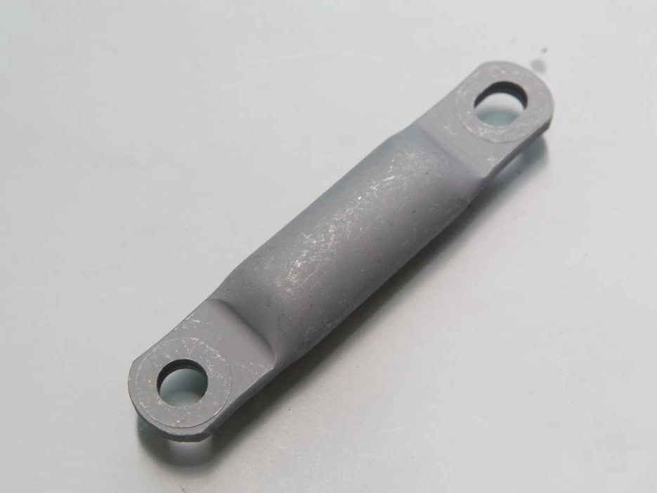
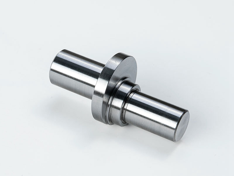
Custom automotive parts machining involves precision CNC processes like milling, turning, drilling, and grinding to create high-quality components for the automotive industry. With techniques such as multi-axis machining and EDM, parts are produced to meet exact specifications, ensuring optimal performance, durability, and fit. This service covers a wide range of automotive applications, from prototypes to production runs.
Automotive Material Selection
Materials such as superalloy, titanium, aluminum, copper, brass, bronze, carbon steel, stainless steel, plastic, and ceramic are chosen for automotive parts for their strength, lightweight properties, durability, corrosion resistance, and heat resistance, ensuring high performance and safety in automotive applications.
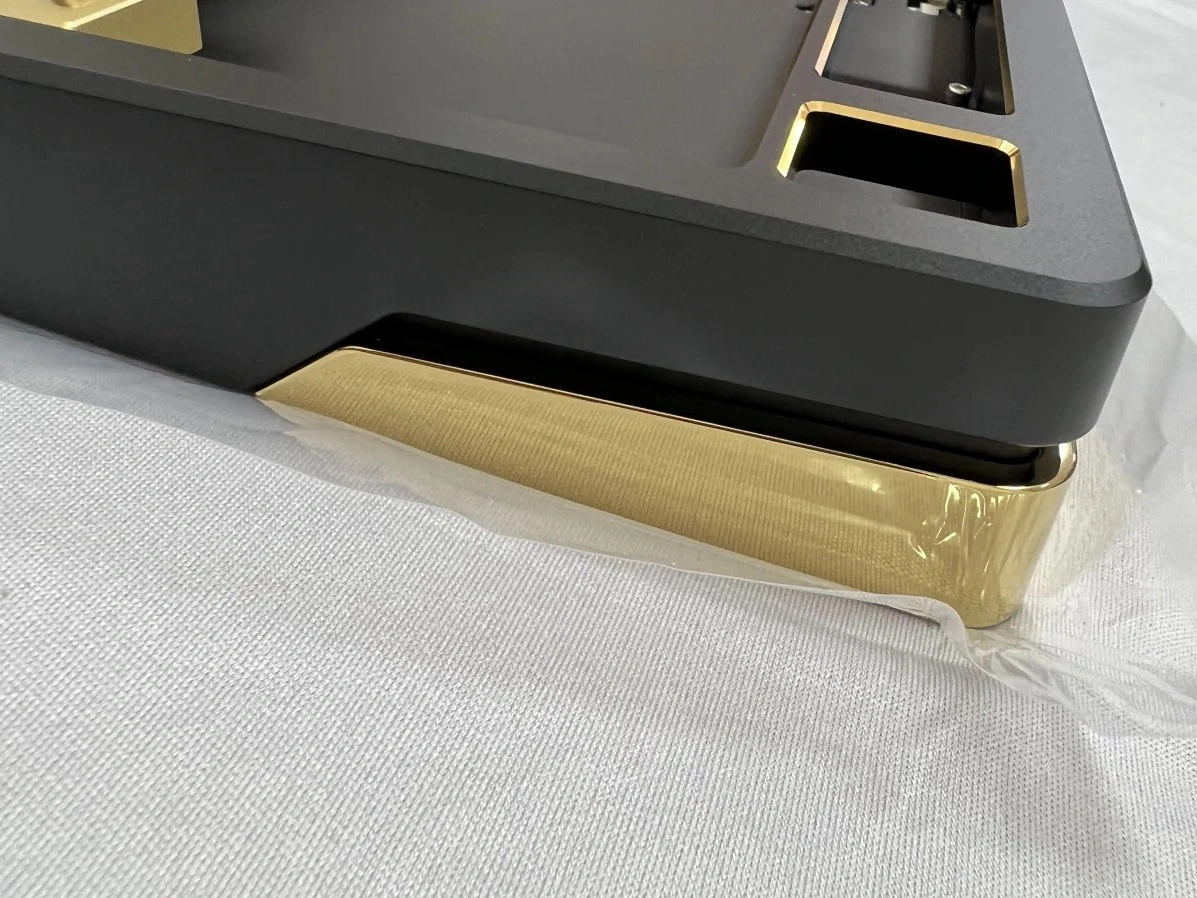
Typical Surface Treatment for Automotive Parts
Typical surface treatments for automotive parts include methods like anodizing, electroplating, powder coating, and PVD to enhance durability, corrosion resistance, and aesthetic appeal. Other treatments like heat treatment, black oxide, and sandblasting improve strength and performance, while finishes such as polishing, tumbling, and lacquering provide a smooth, visually appealing surface. These treatments ensure parts meet demanding automotive standards.
Learn More
Thermal Coating
Learn More
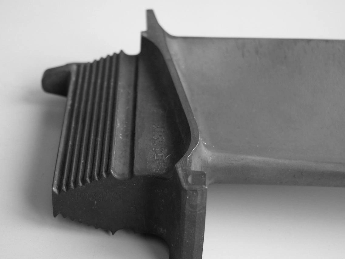
As Machined
Learn More
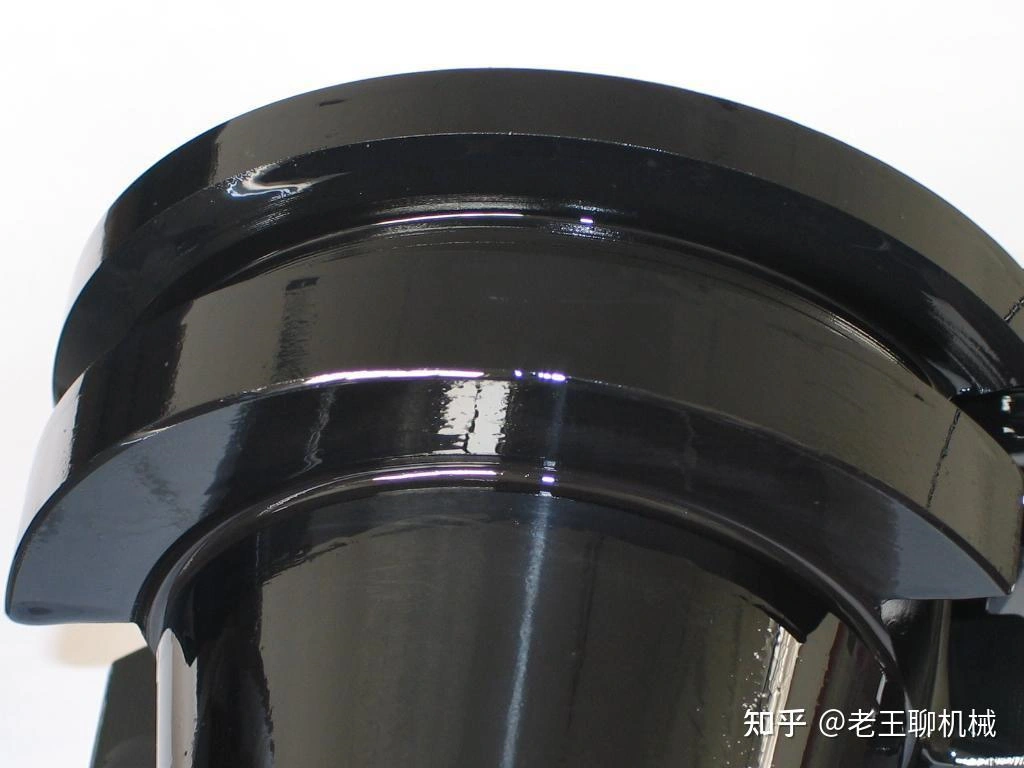
Painting
Learn More
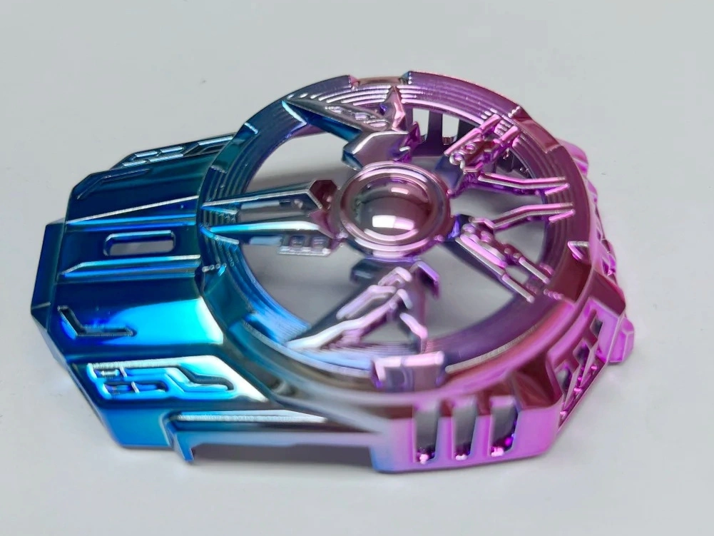
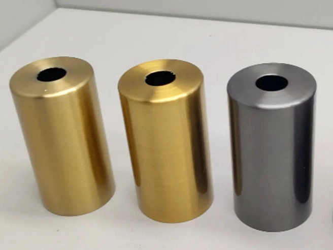
PVD (Physical Vapor Deposition)
Learn More
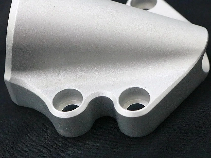
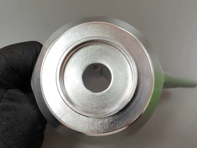
Sandblasting
Learn More
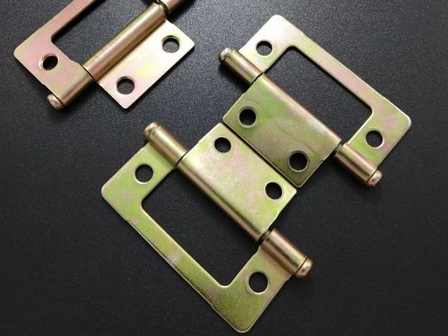
Electroplating
Learn More
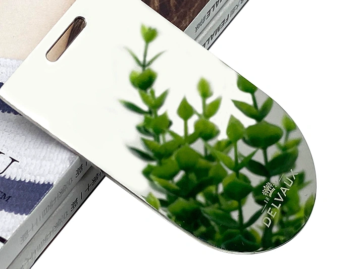
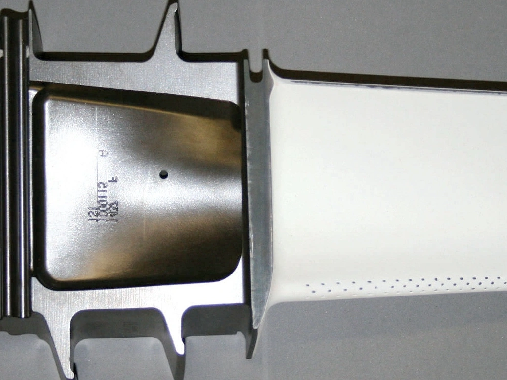
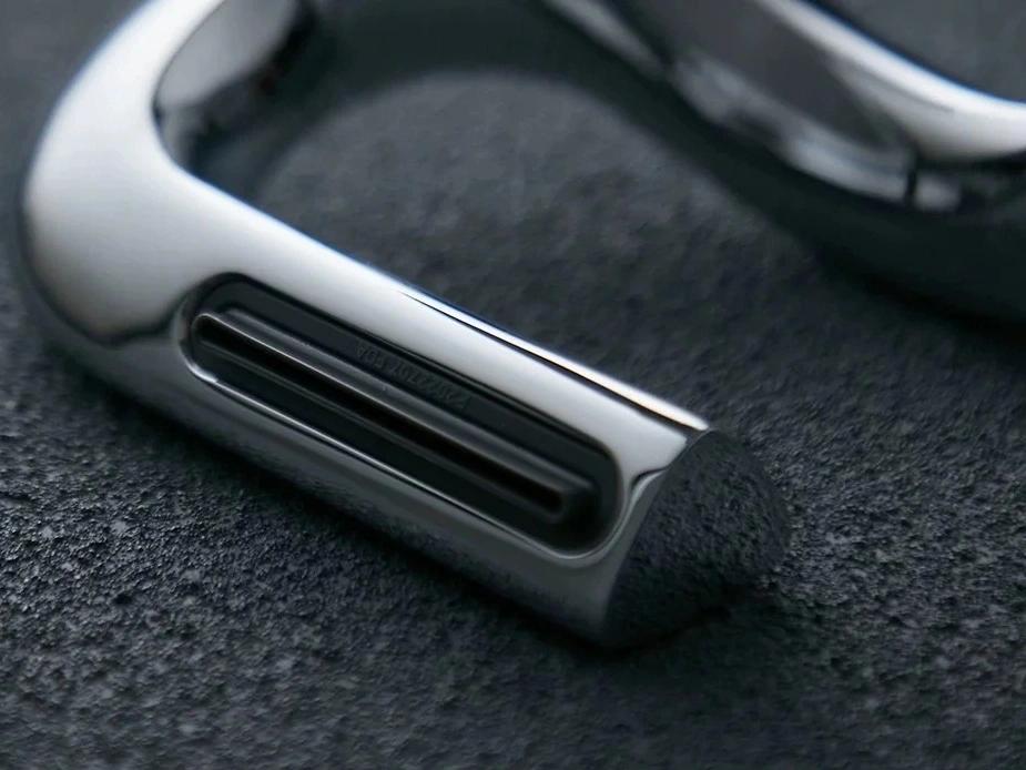
Polishing
Learn More
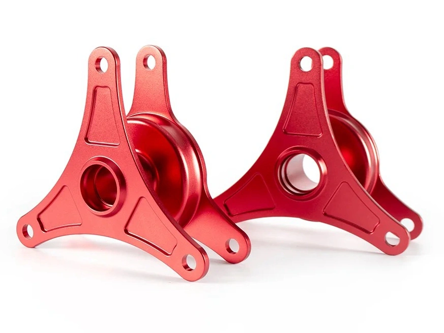
Anodizing
Learn More
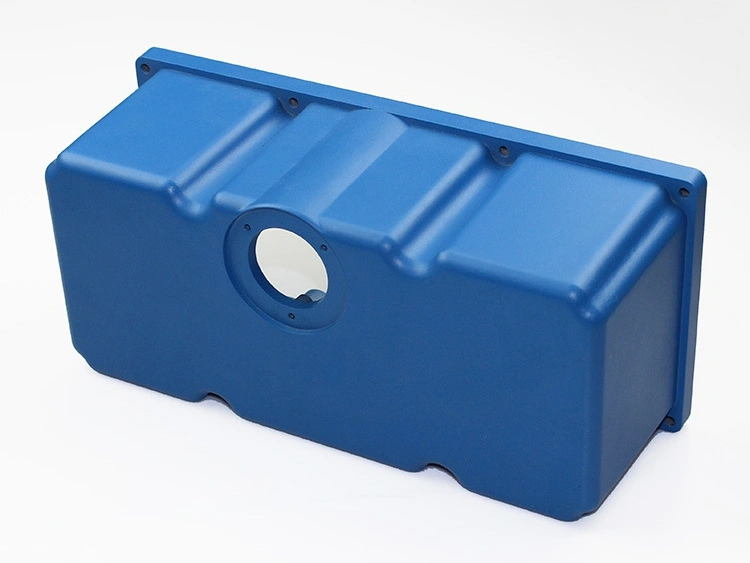
Powder Coating
Learn More
Electropolishing
Learn More
Passivation
Learn More
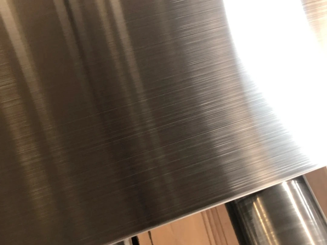
Brushing
Learn More
Black Oxide
Learn More
Heat Treatment
Learn More
Thermal Barrier Coating (TBC)
Learn More
Tumbling
Learn More
Alodine
Learn More
Chrome Plating
Learn More
Phosphating
Learn More
Nitriding
Learn More
Galvanizing
Learn More
UV Coating
Learn More
Lacquer Coating
Learn More
Teflon Coating
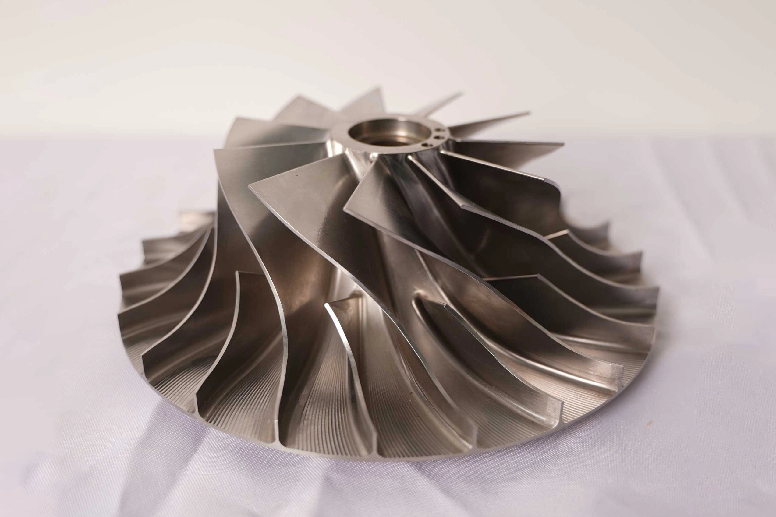
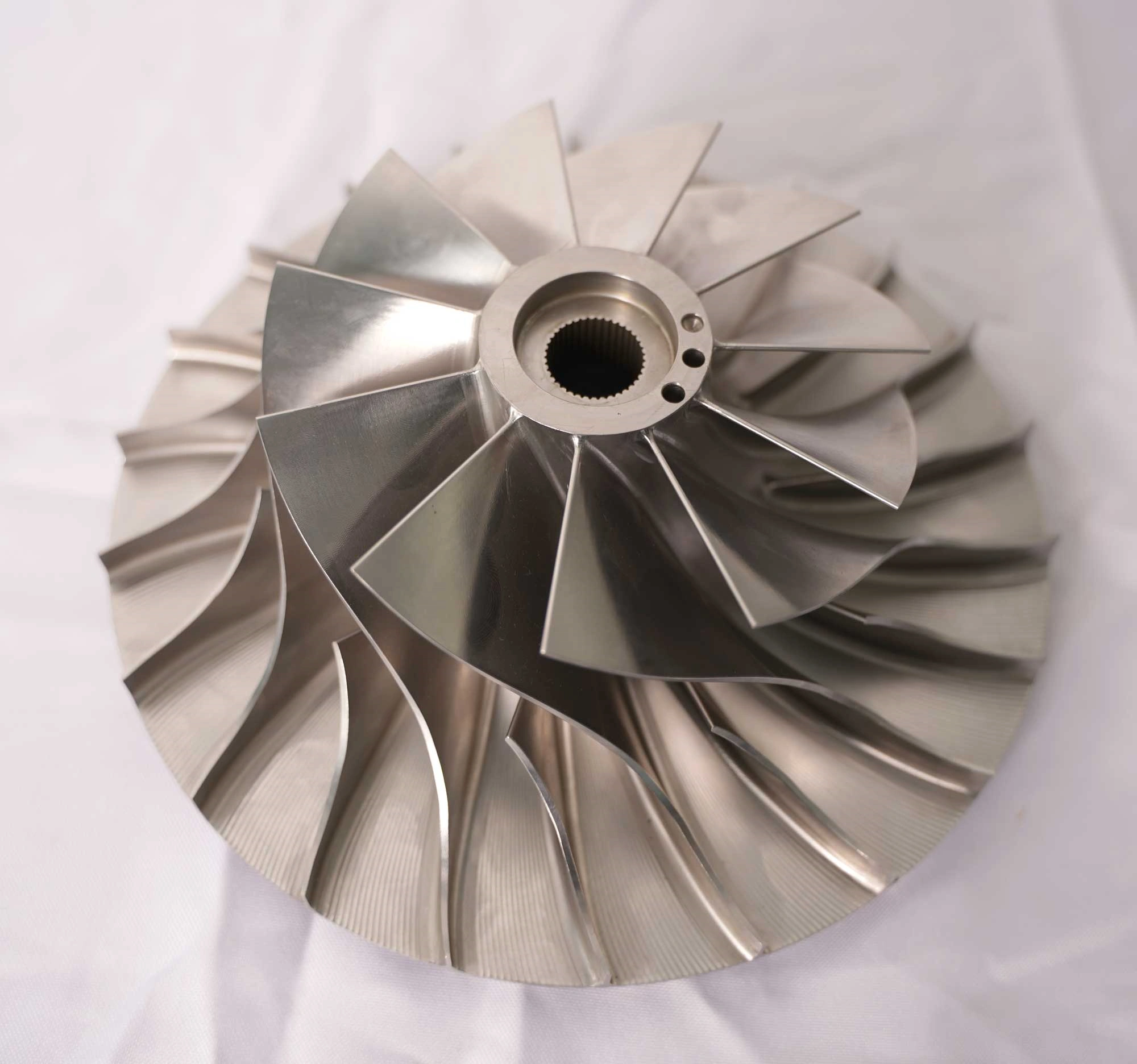
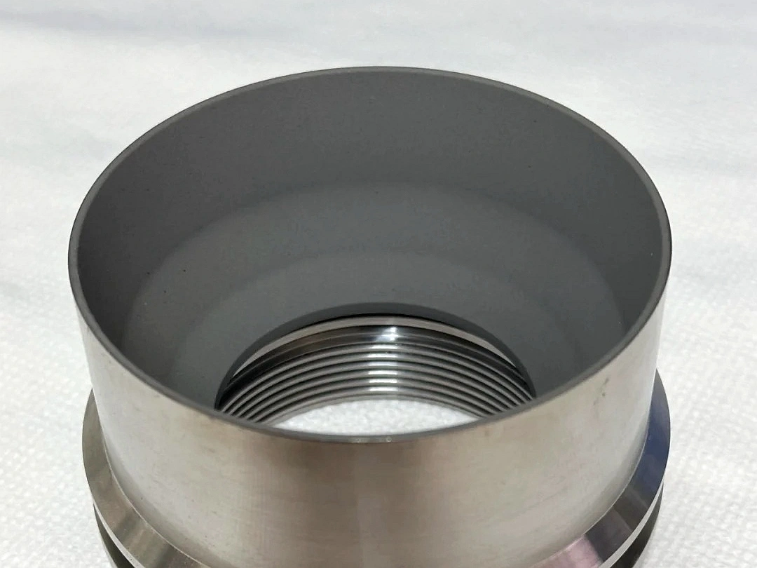
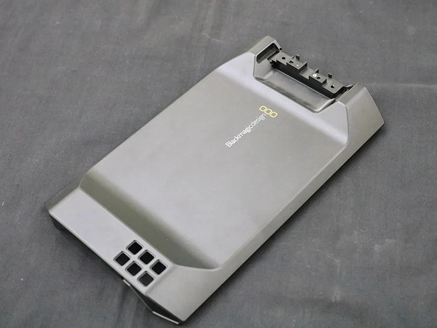
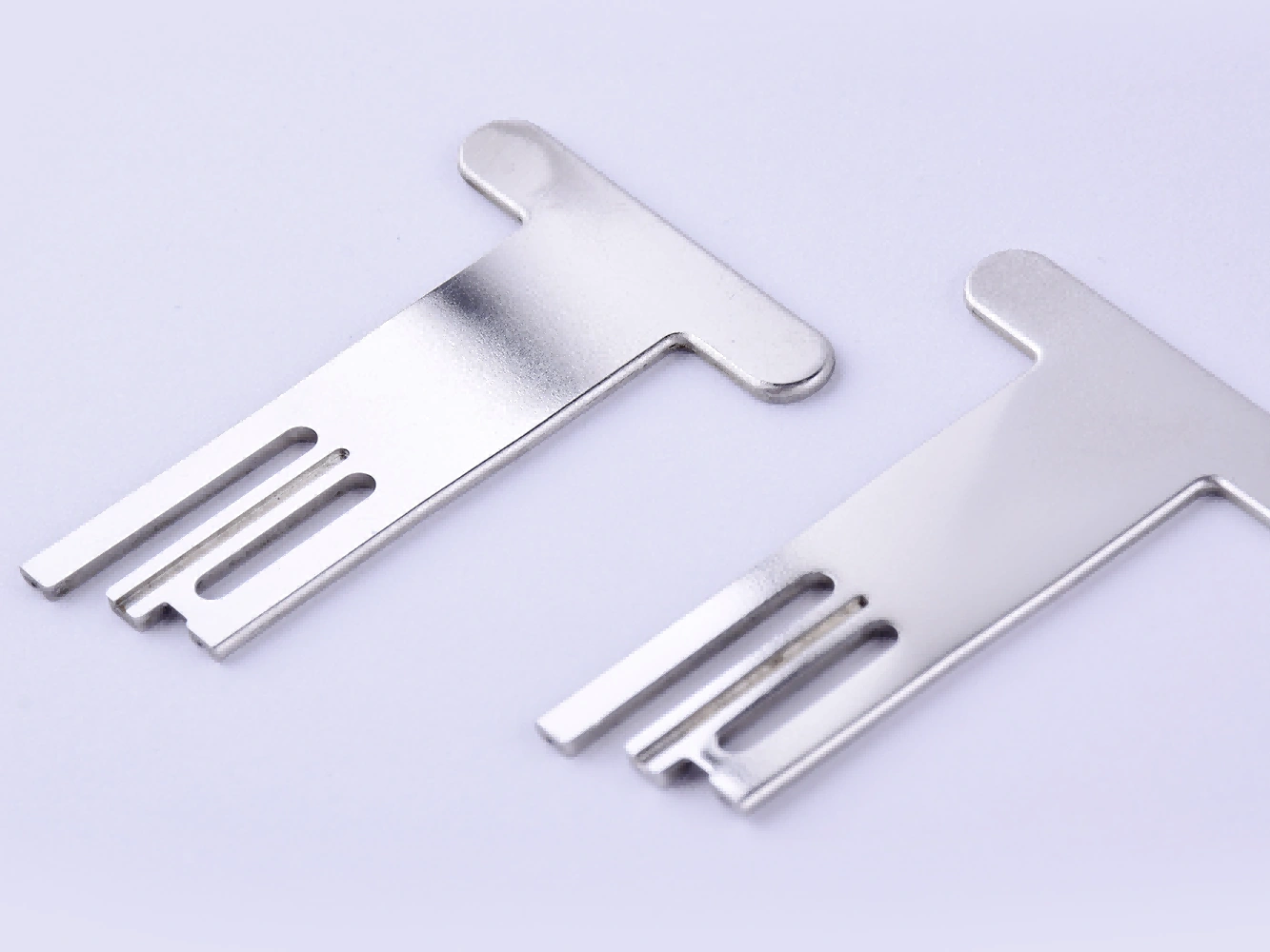
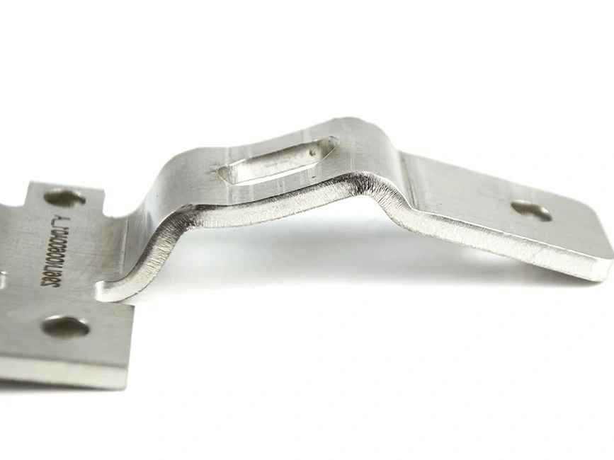
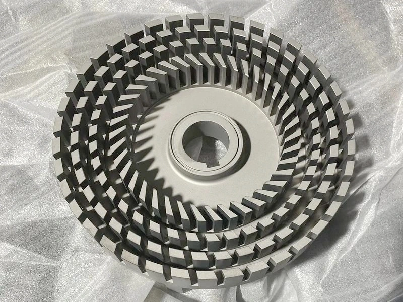
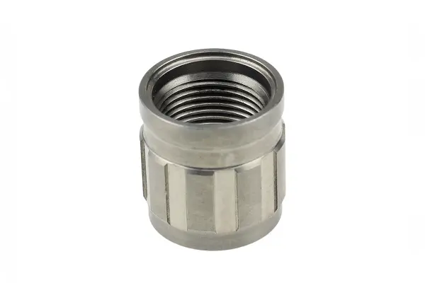
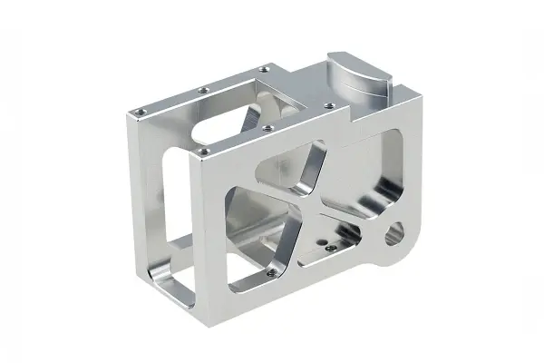
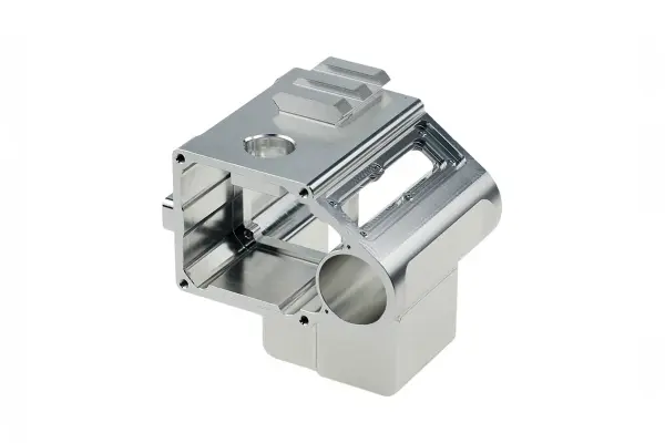
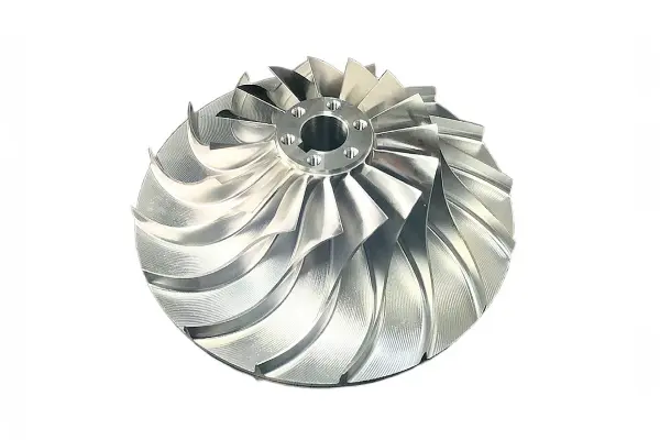
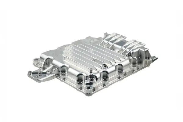
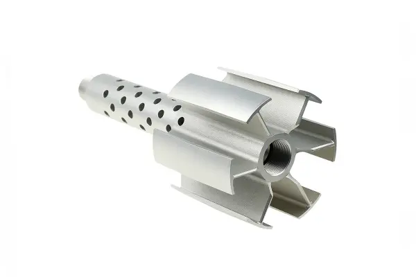
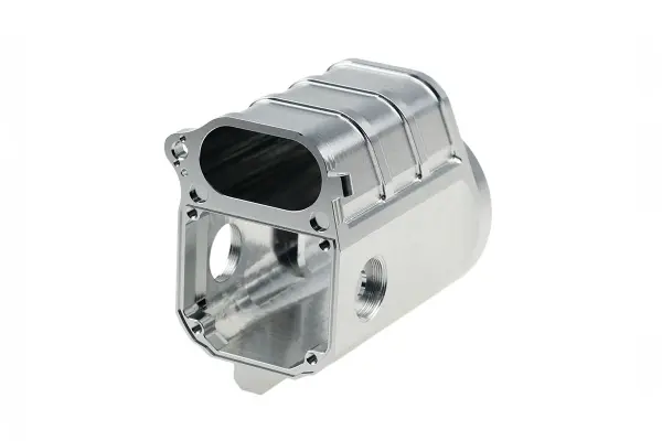
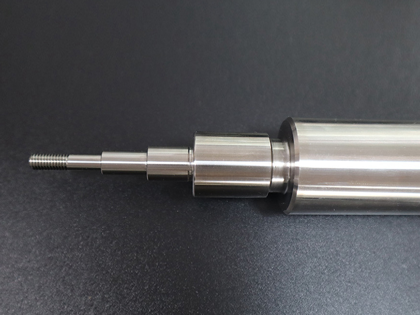
Automotive CNC Machining Components
CNC machining provides precision parts for the automotive industry, from engine components to suspension systems, ensuring high performance, reliability, and safety in every vehicle.
Let's Start A New Project Today
Guide to Automotive Components Design and Manufacturing
Automotive part design demands fatigue durability, cost-efficiency, dimensional control, and process compatibility. This guide outlines critical design principles to ensure reliable performance and manufacturability in mass automotive production.
Frequently Asked Questions
Explore Related Resources

Neway Precision Works Ltd.
No.3 Lefushan Industry West Road
Fenggang, Dongguan, China
ZIP 523000
Solutions
Copyright © 2026 Machining Precision Works Ltd.All Rights Reserved.