English
Custom Parts Manufacturing Solutions
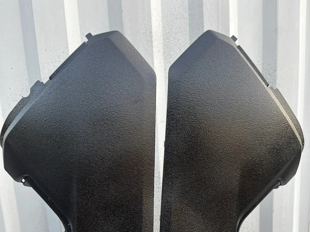
Industrial Equipment Parts Manufacturing Service
Neway offers Industrial Equipment Parts Manufacturing, providing CNC Machining, 3D Printing, Vacuum Casting, Die Casting, and Injection Molding. We deliver durable, high-precision components designed to meet the demanding needs of industrial applications.

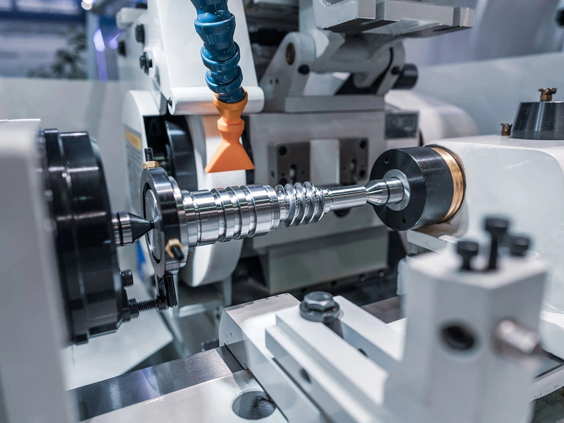
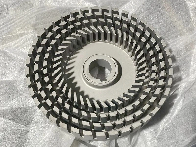
Industrial Equipment Parts Machining
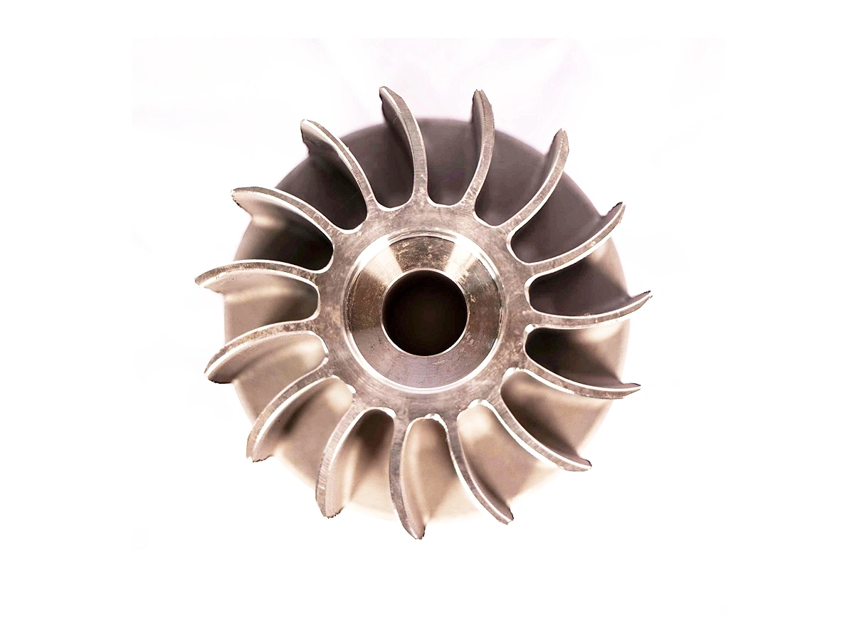
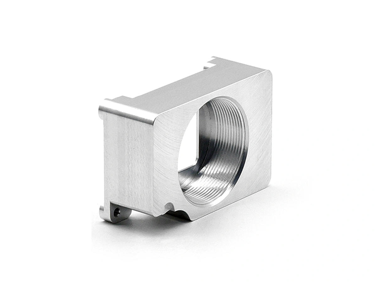
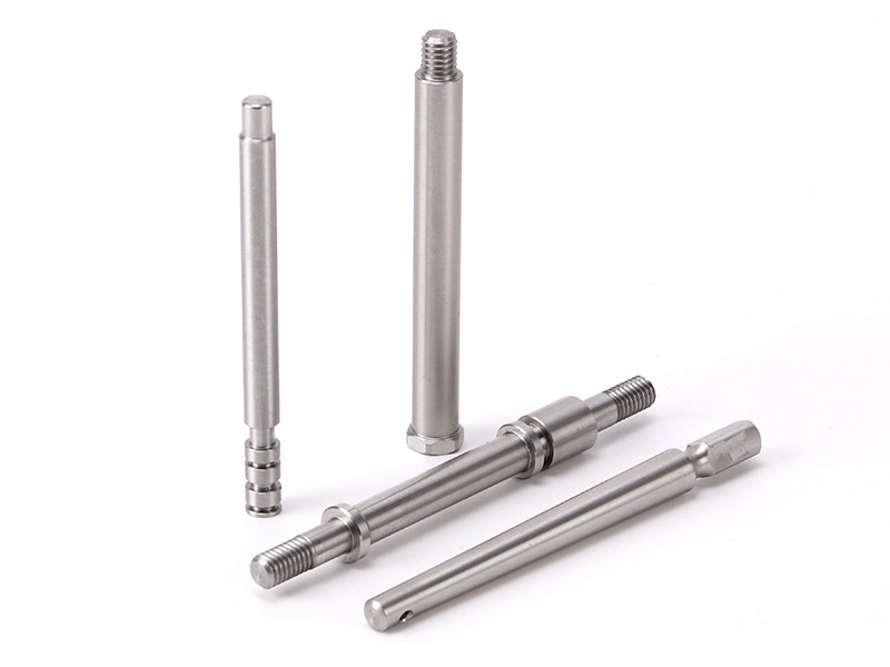
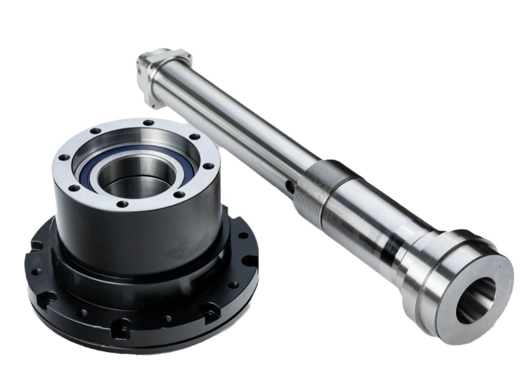
Industrial equipment parts machining involves precision manufacturing processes such as CNC milling, turning, drilling, boring, grinding, and EDM to create high-quality components. Utilizing multi-axis and precision machining techniques, these services ensure the production of complex and accurate parts for industrial machinery. The result is durable, reliable equipment parts optimized for performance and longevity in demanding applications.
Industrial Equipment Material Selection
Industrial equipment manufacturing requires durable materials that can withstand high stress and harsh environments. Key materials include superalloys for high-temperature resistance, titanium for strength-to-weight ratio, stainless steel for corrosion resistance, aluminum for lightweight components, and plastics for non-structural, insulating, or sealing applications.
Typical Surface Treatment for Industrial Equipment Parts
Typical surface treatments for industrial equipment parts include processes like anodizing, electroplating, powder coating, and PVD to enhance durability, corrosion resistance, and aesthetic appearance. Methods such as sandblasting, passivation, and polishing improve surface finish, while heat treatments and thermal barrier coatings offer thermal stability. These treatments ensure parts perform efficiently under demanding industrial conditions.
Learn More
Thermal Coating
Learn More
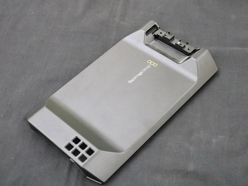
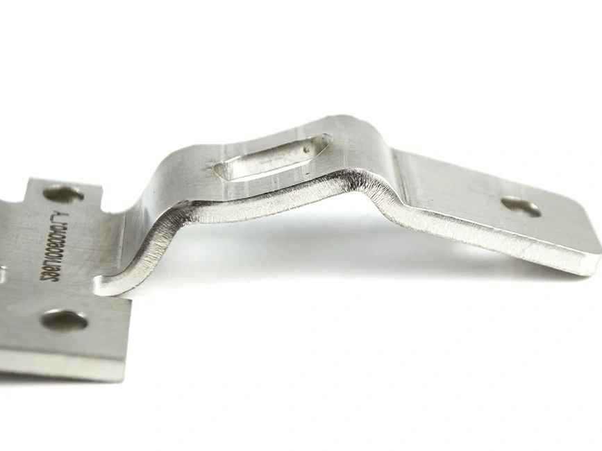
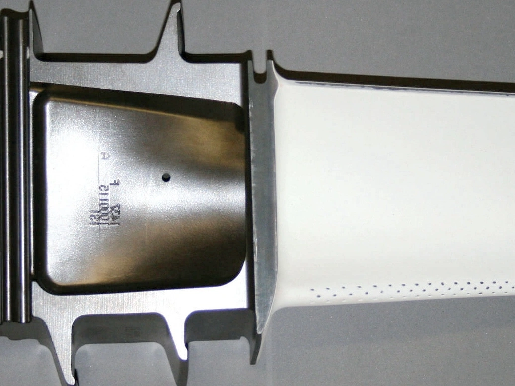
As Machined
Learn More
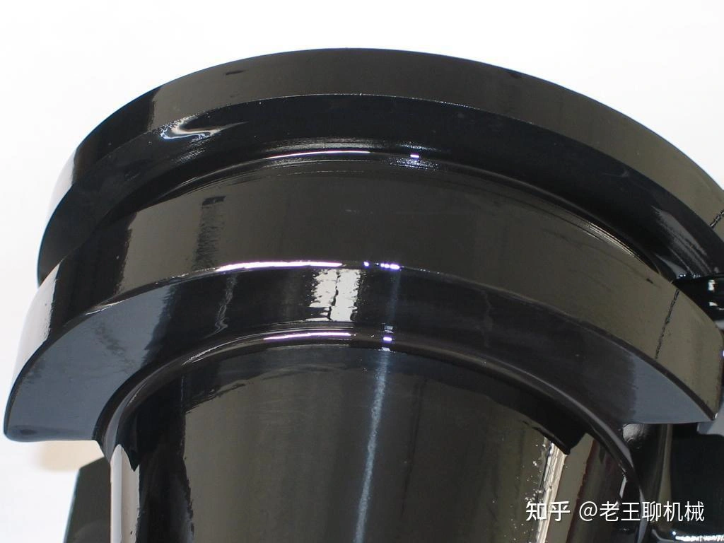
Painting
Learn More
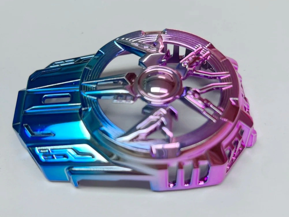
PVD (Physical Vapor Deposition)
Learn More
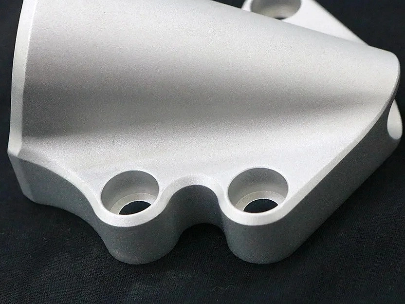
Sandblasting
Learn More
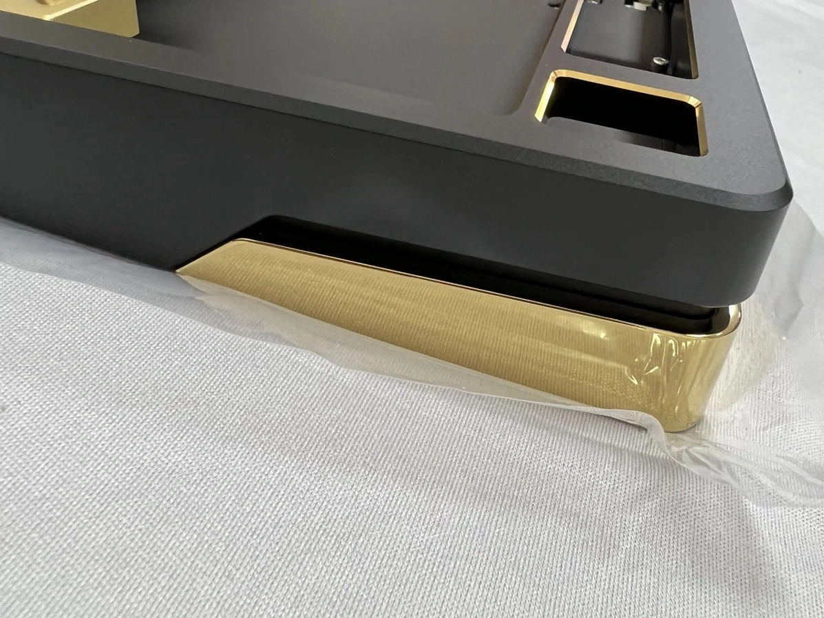
Electroplating
Learn More
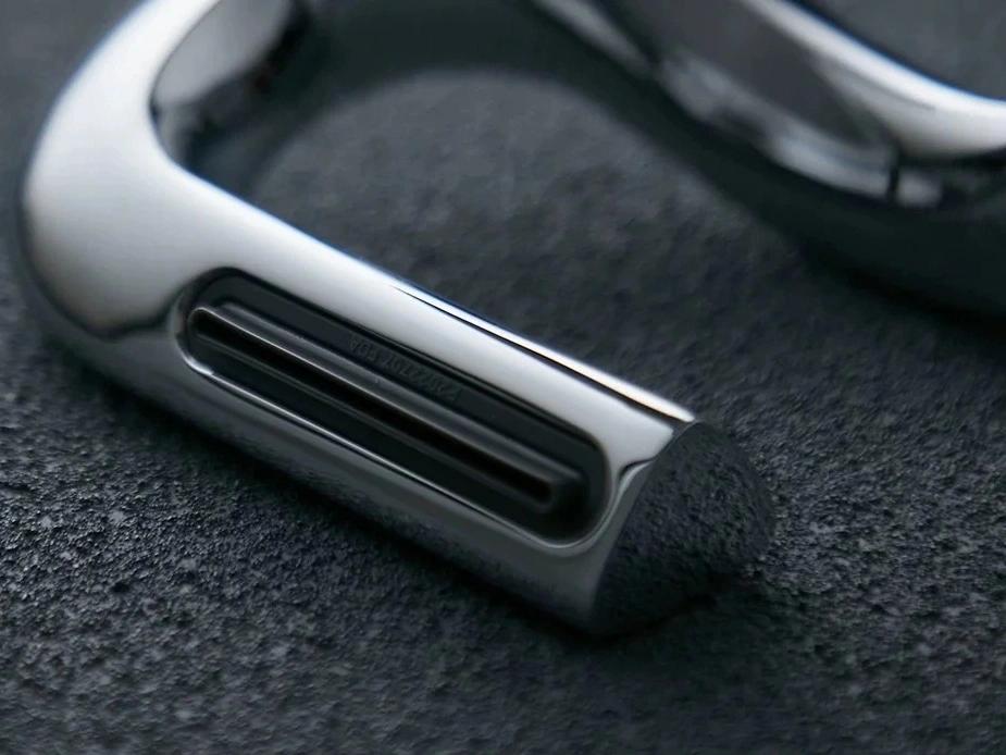
Polishing
Learn More
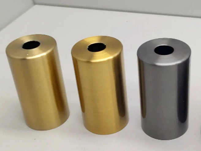
Anodizing
Learn More
Powder Coating
Learn More
Electropolishing
Learn More
Passivation
Learn More
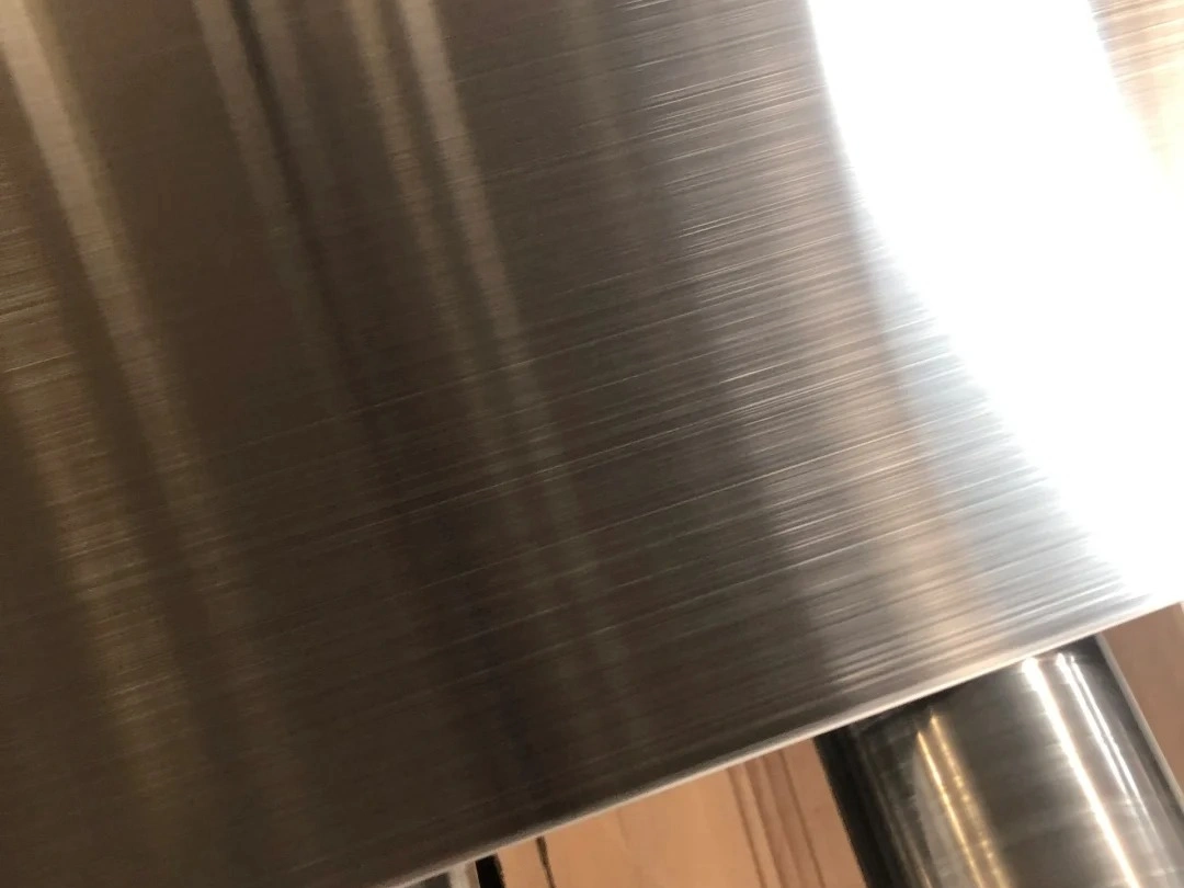
Brushing
Learn More
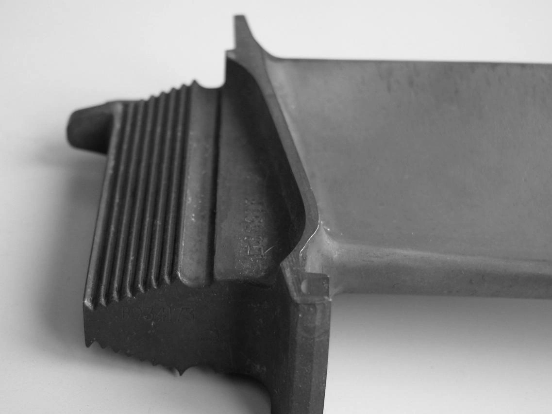
Black Oxide
Learn More
Heat Treatment
Learn More
Thermal Barrier Coating (TBC)
Learn More
Tumbling
Learn More
Alodine
Learn More
Chrome Plating
Learn More
Phosphating
Learn More
Nitriding
Learn More
Galvanizing
Learn More
UV Coating
Learn More
Lacquer Coating
Learn More
Teflon Coating
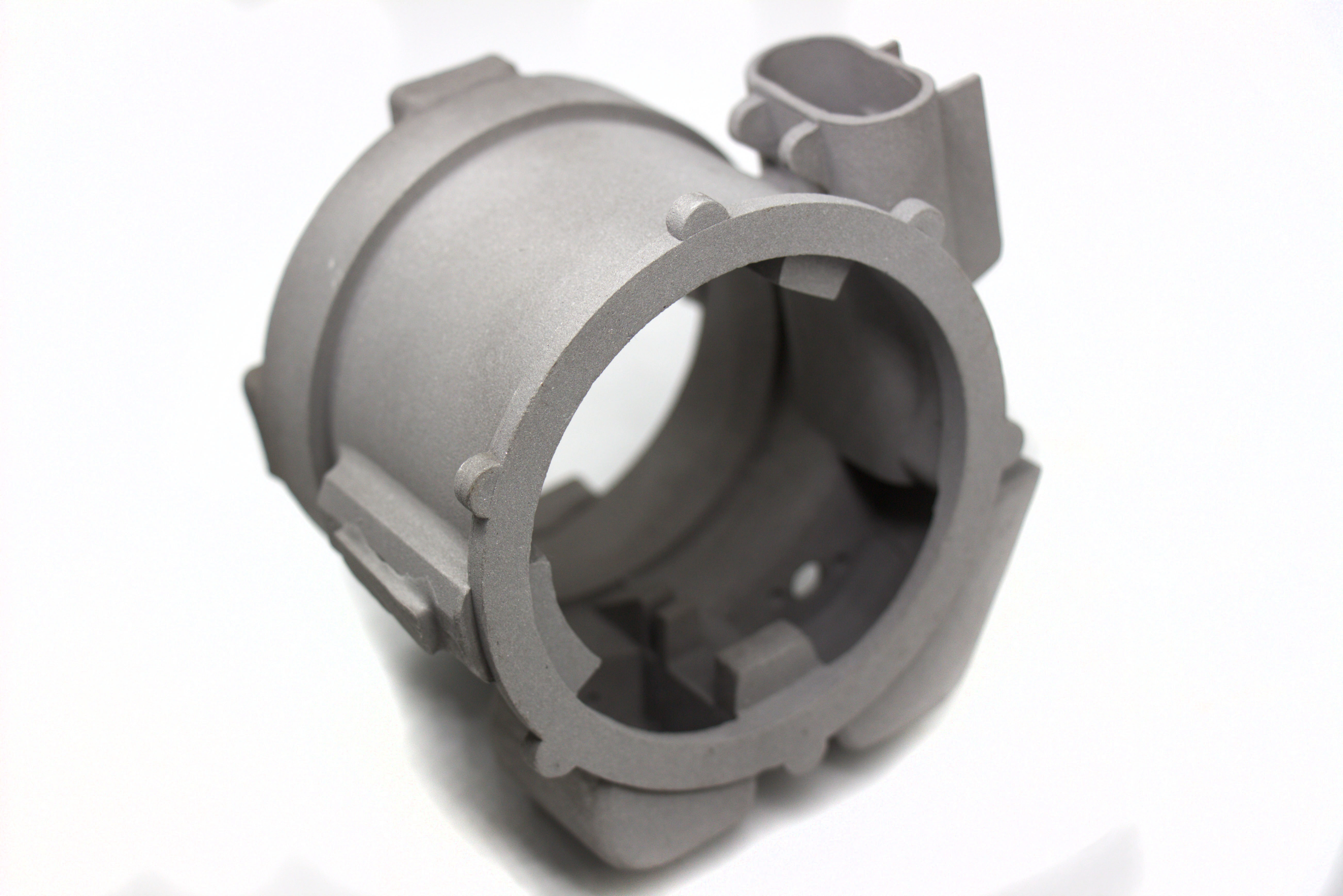
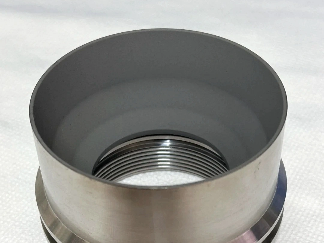
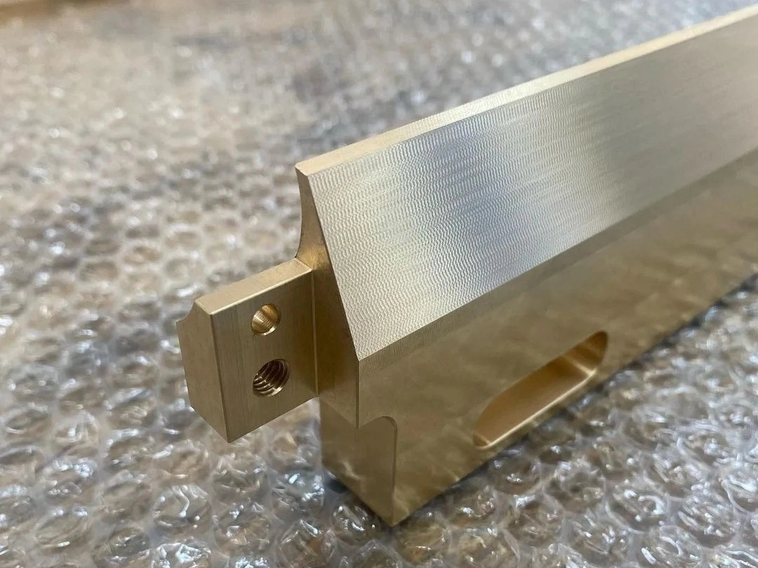
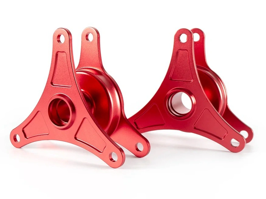
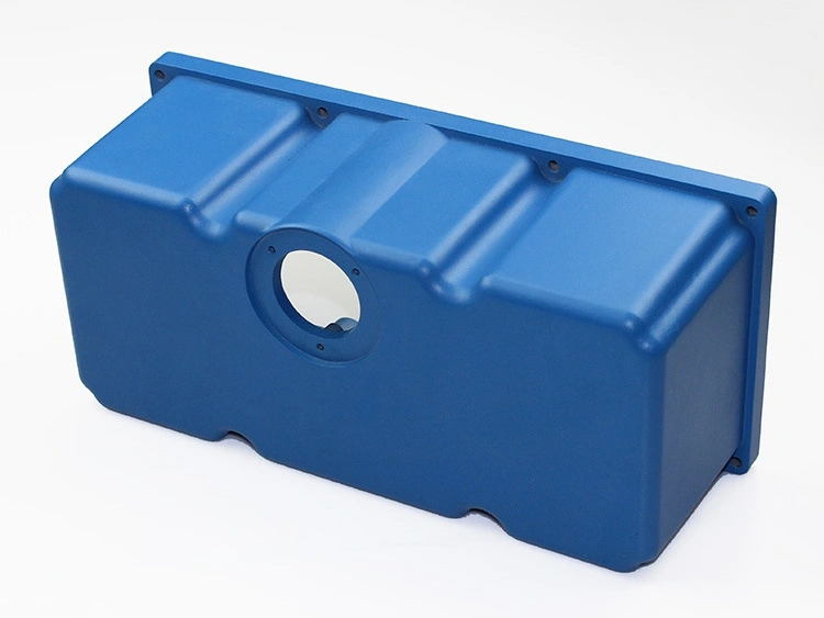
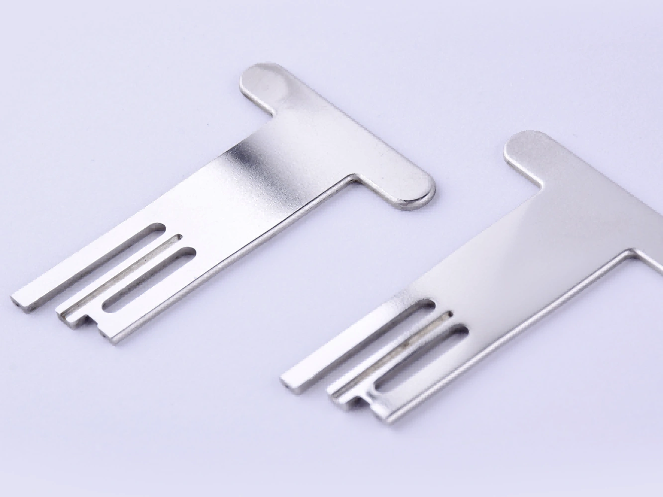
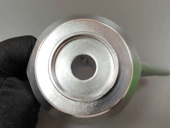
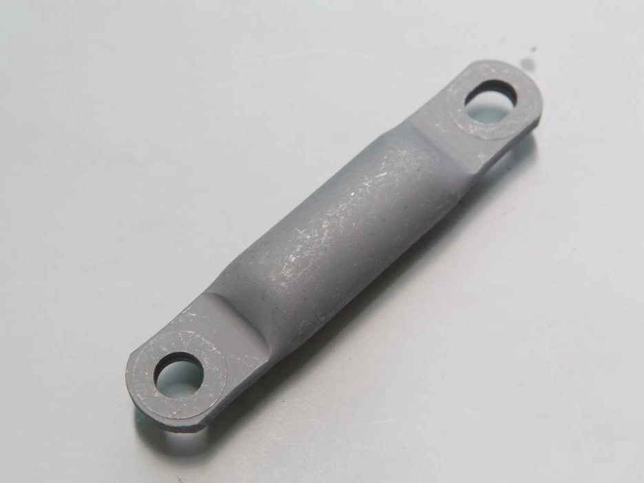
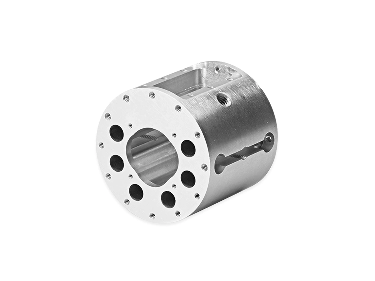
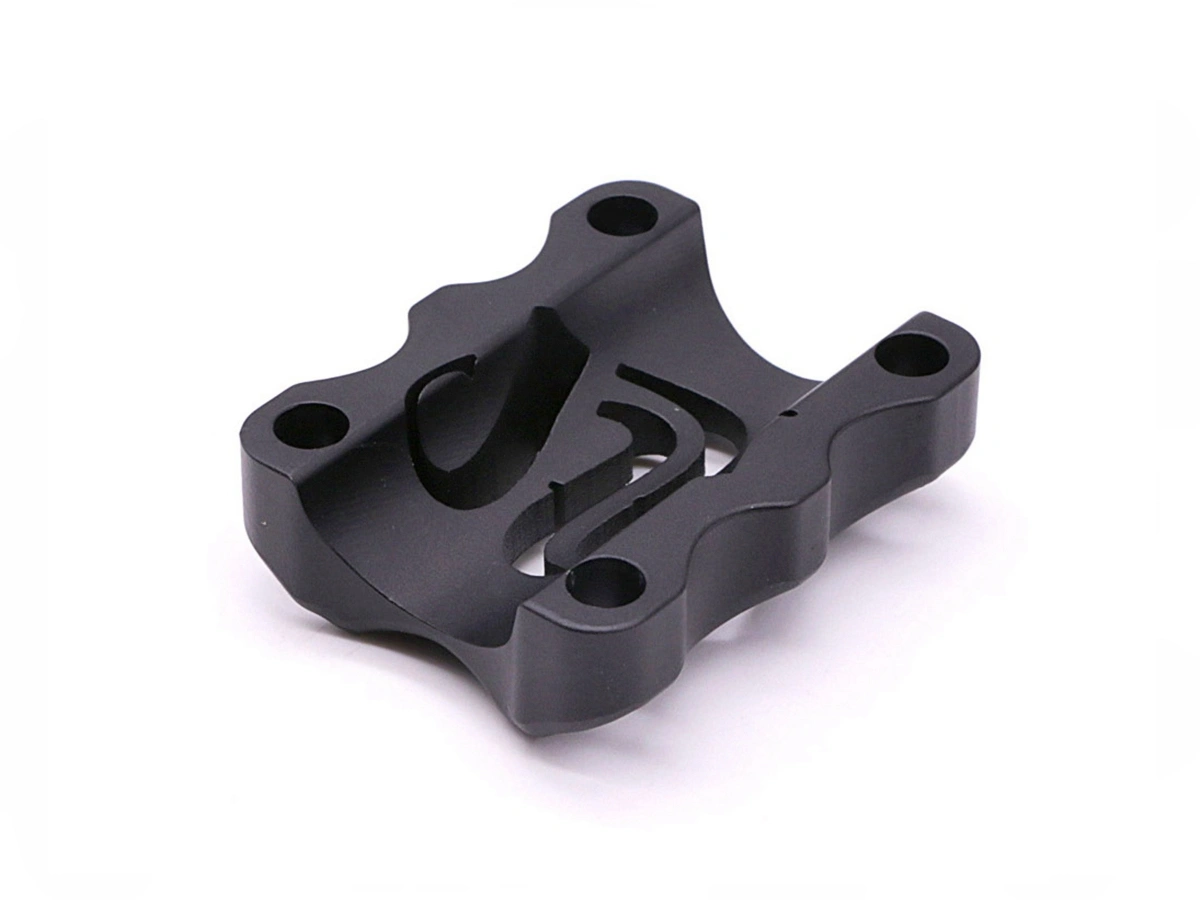
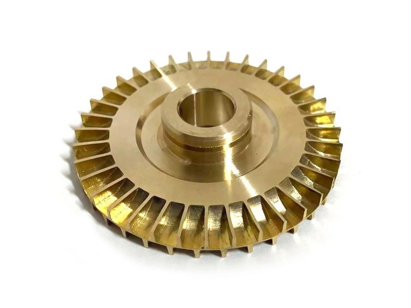
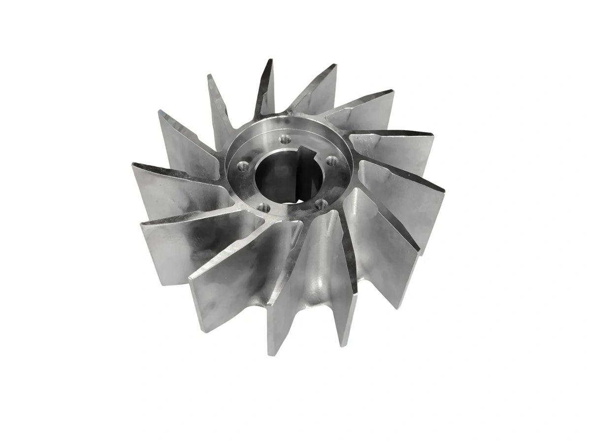
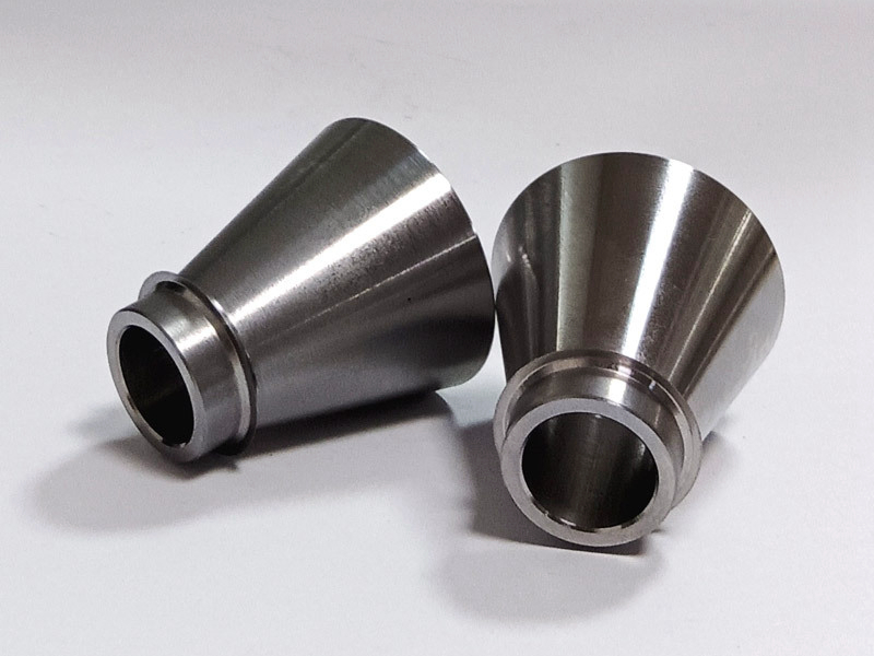
CNC Machined Industrial Equipment Parts
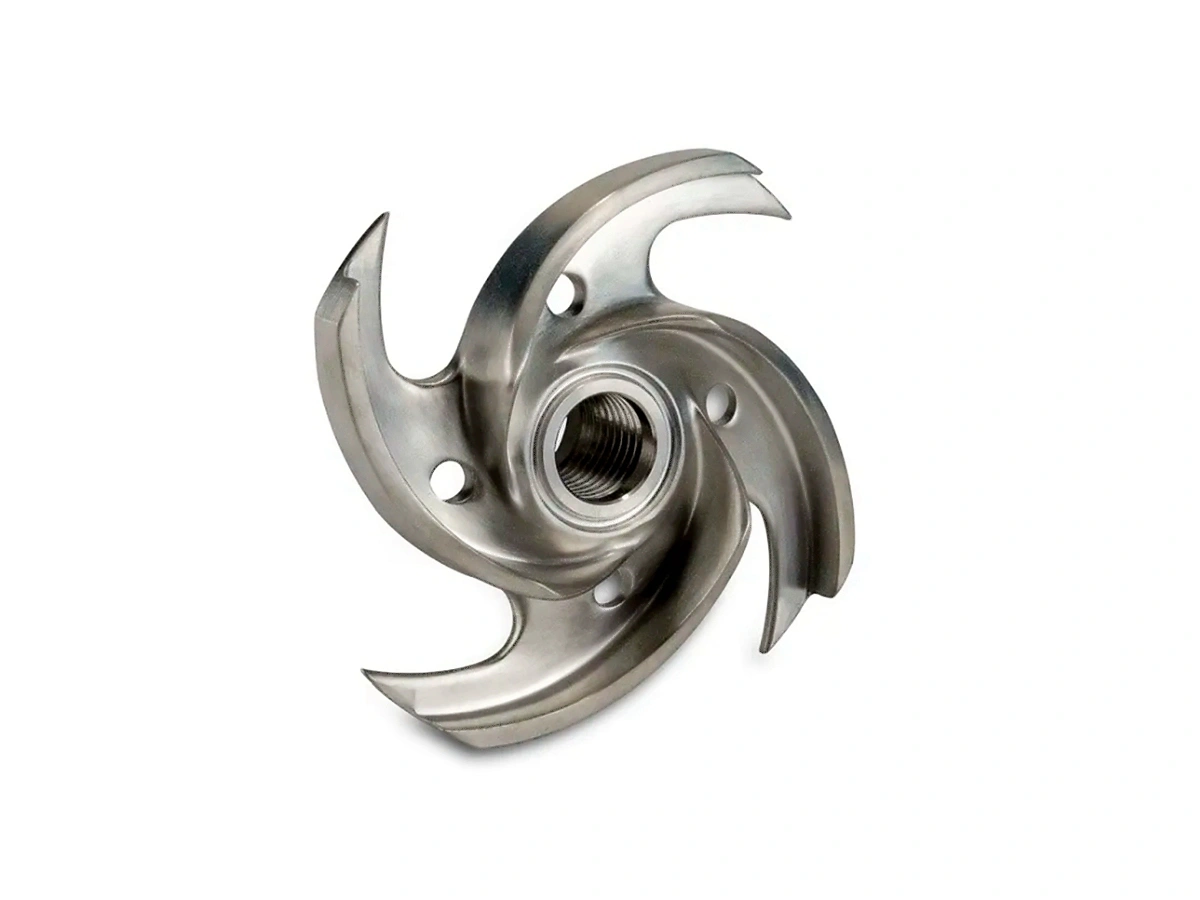
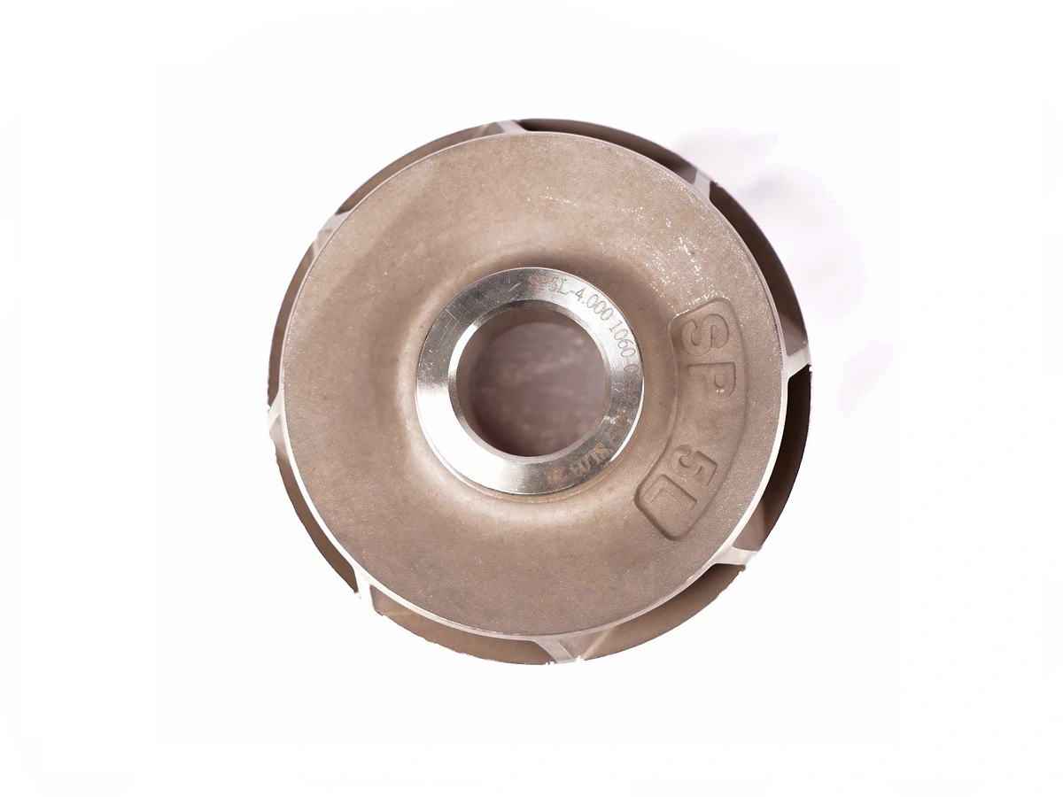
Industrial equipment benefits from CNC machining in producing parts like pumps, valves, and compressors, providing high-strength, precision-engineered components that ensure smooth operation and longevity.
Let's Start A New Project Today
Guide to Industrial Equipment Parts Design
Industrial equipment parts require design strategies that ensure high structural integrity, manufacturing precision, serviceability, and compliance. This guide details best practices for high-load, precision-machined, and field-operational components.
Custom Industrial Equipment Parts Manufacturing Considerations
Precision manufacturing of custom industrial equipment parts requires robust materials, process stability, tight tolerances, and global compliance. This guide outlines engineering-driven production principles for scalable, high-performance parts.
Frequently Asked Questions
Explore Related Resources

Neway Precision Works Ltd.
No.3 Lefushan Industry West Road
Fenggang, Dongguan, China
ZIP 523000
Solutions
Copyright © 2026 Machining Precision Works Ltd.All Rights Reserved.