English
Custom Parts Online Rapid Prototyping Service
Neway offers a Custom Parts Online Rapid Prototyping Service, providing fast, precise prototypes using CNC Machining, 3D Printing, and Rapid Molding. Our service ensures quick turnaround, high accuracy, and customized solutions for your unique part requirements.
- CNC Machining Prototyping Service
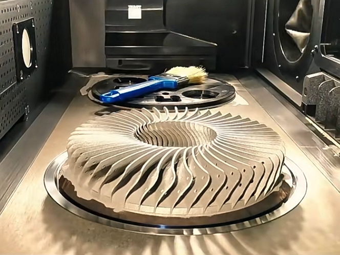
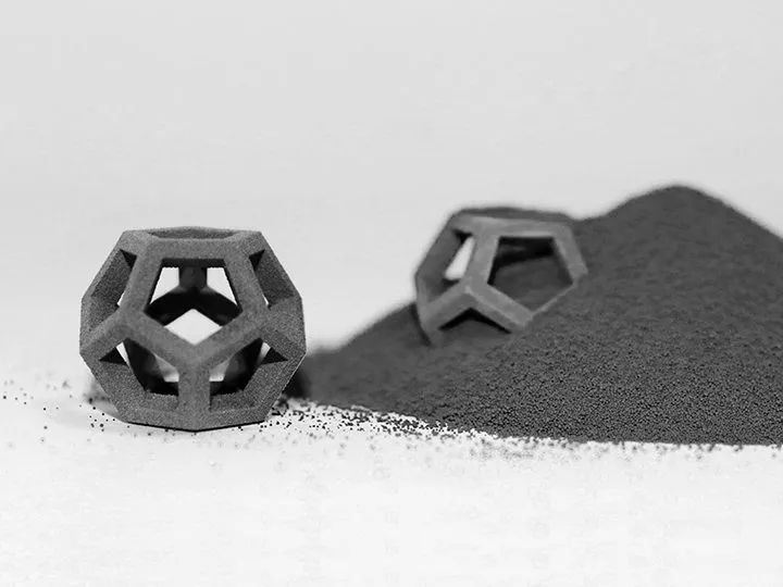
- 3D Printing Prototyping Service
- Rapid Molding Prototyping Service
- Expedited Prototyping Service >>
Send us your designs and specifications for a free quotation
All uploaded files are secure and confidential
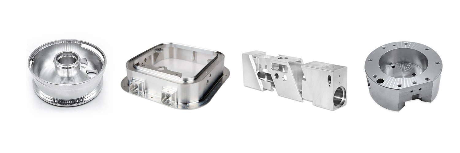
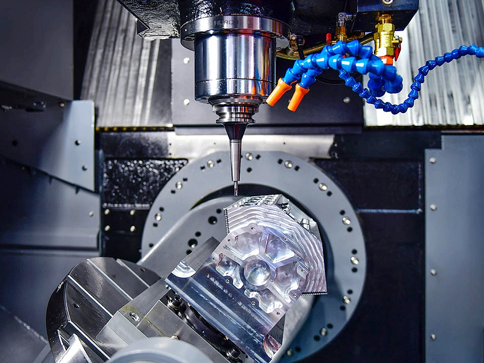
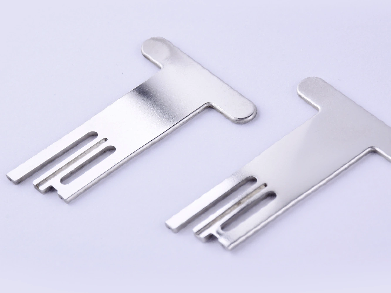
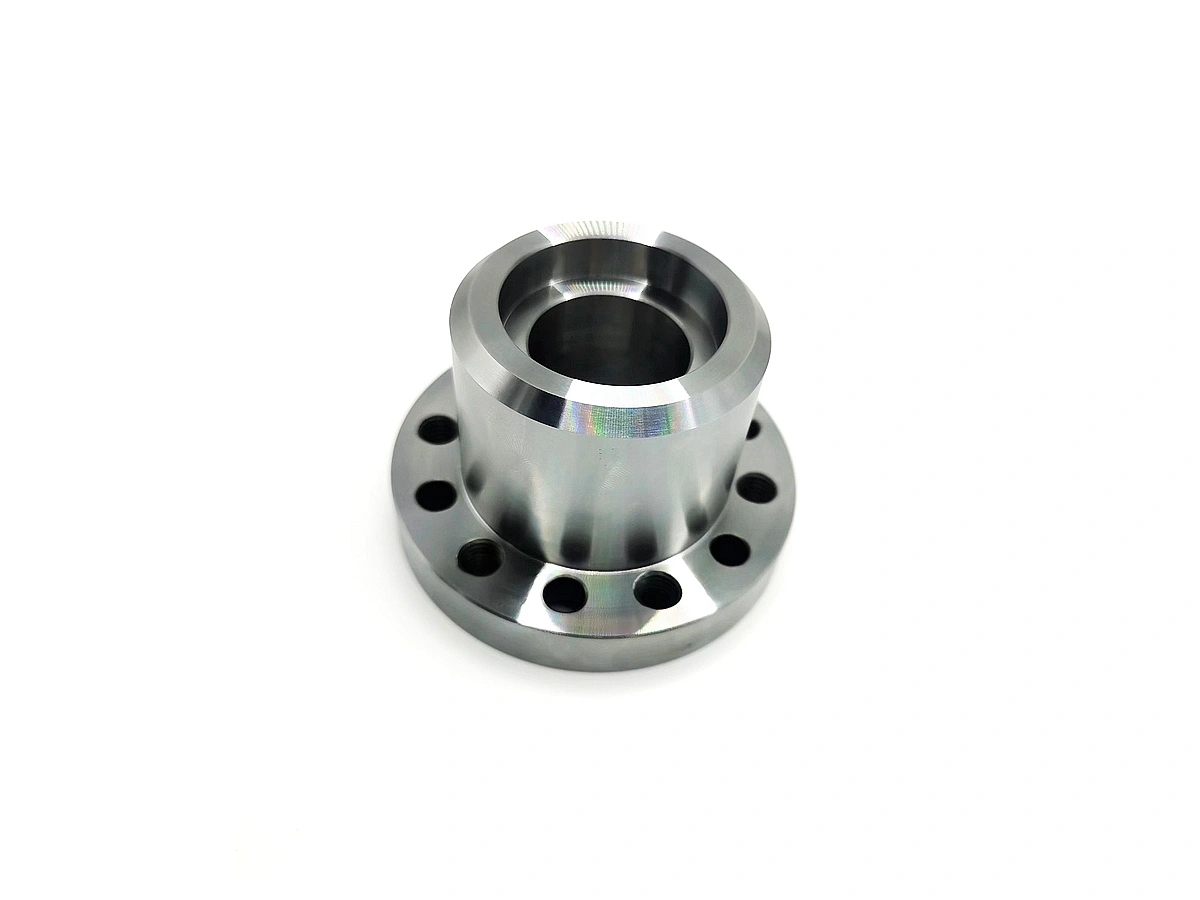
Machining Prototyping Capabilities
Neway's Machining Prototyping capabilities include CNC Machining, CNC Milling, CNC Turning, CNC Drilling, CNC Boring, CNC Grinding, Multi-Axis Machining, Precision Machining, and Electrical Discharge Machining (EDM). We deliver high-precision prototypes with exceptional accuracy and fast turnaround.
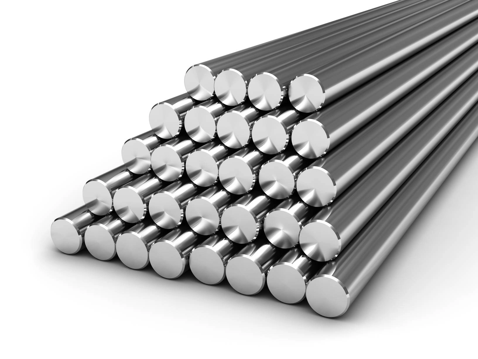
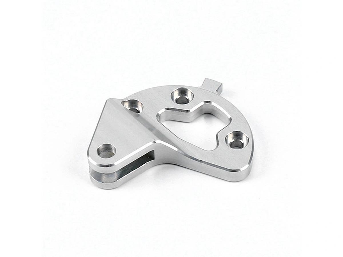
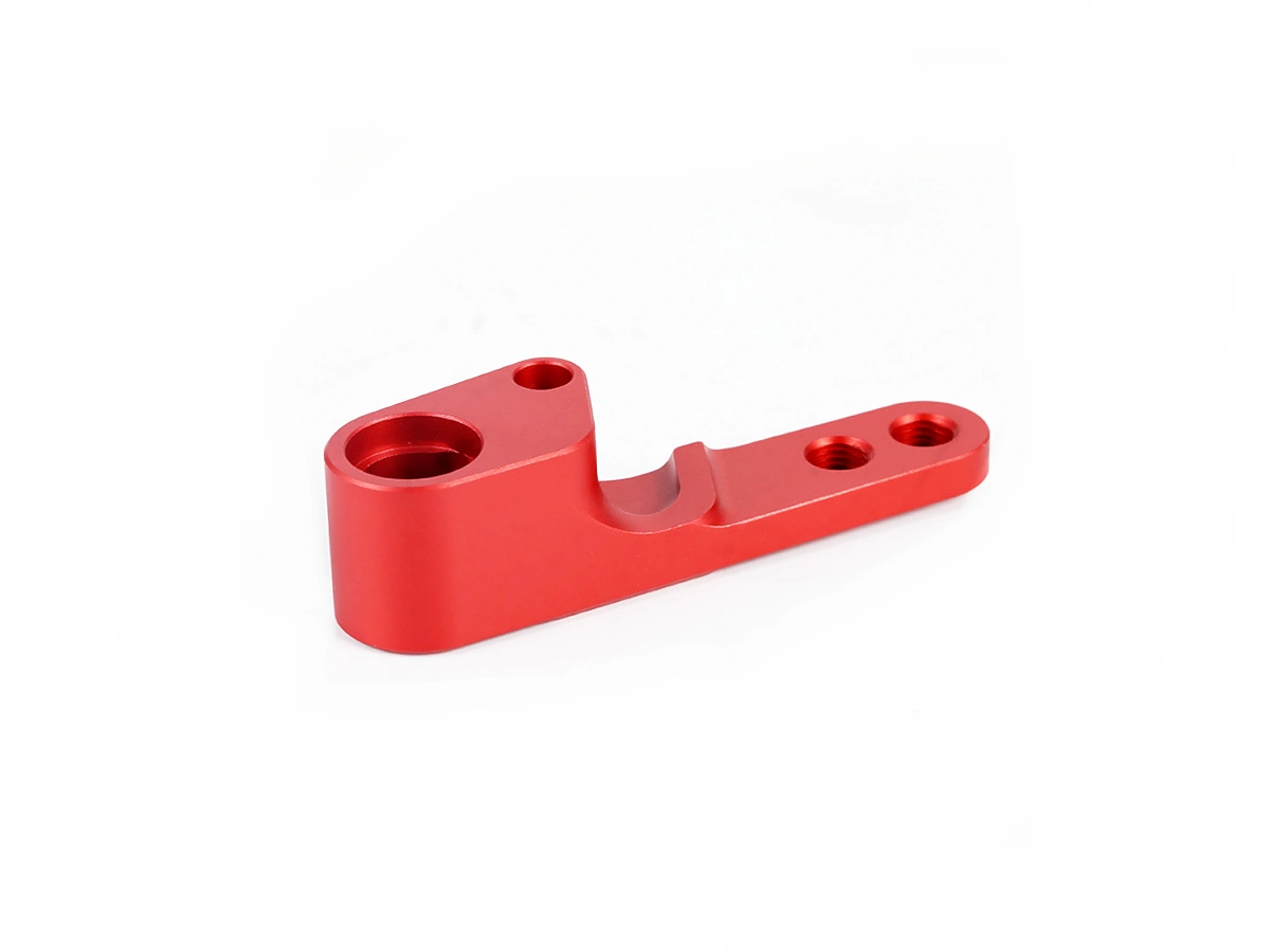
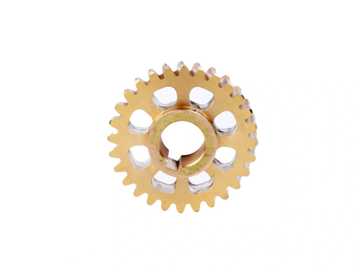
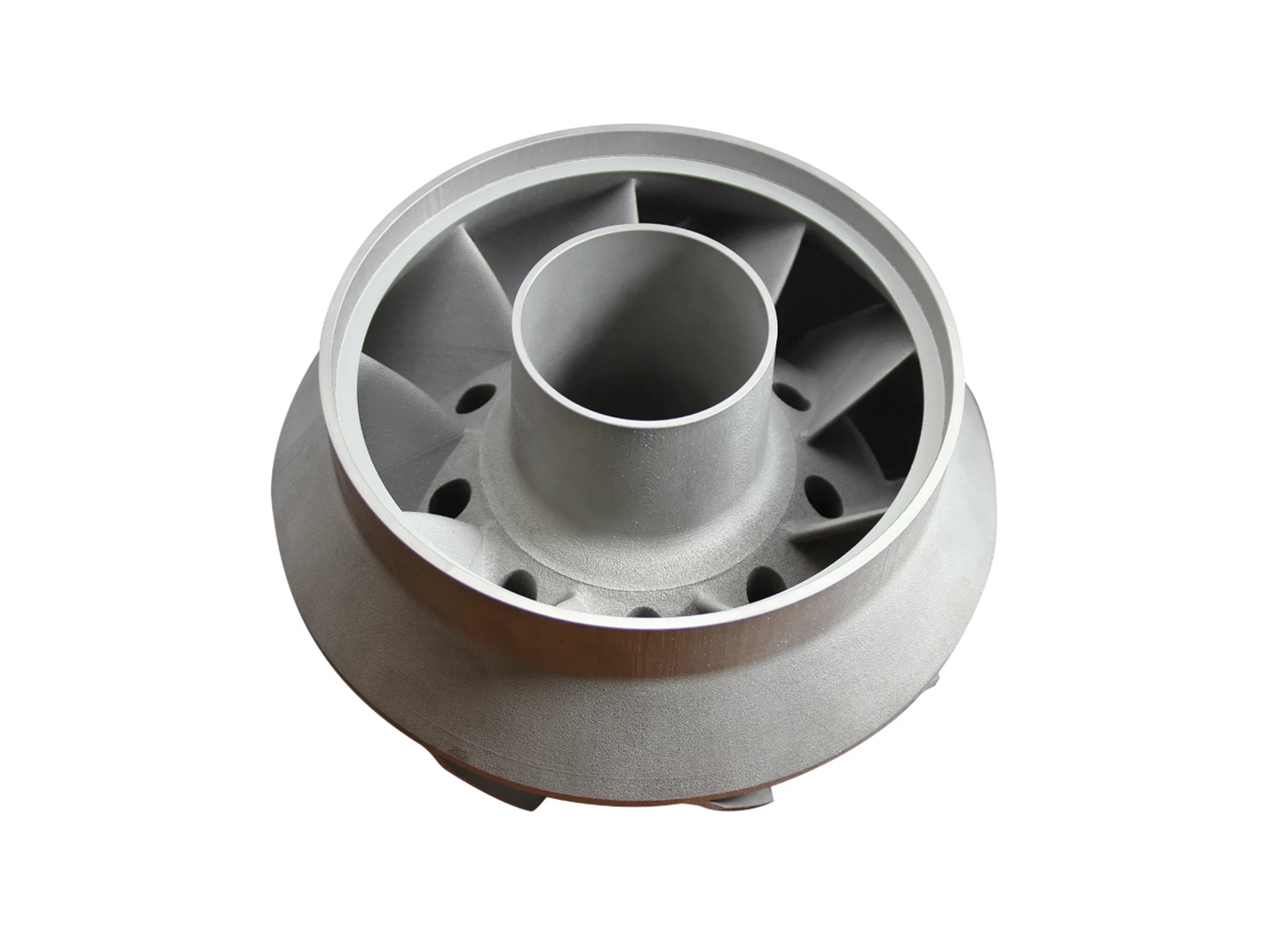
Machining Prototyping Materials Solution
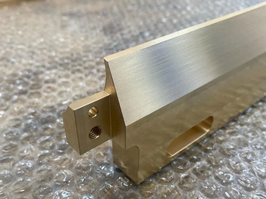
Neway’s Machining Prototyping Materials Solution offers a wide range of materials, including Superalloy, Titanium, Aluminum, Copper, Brass, Bronze, Carbon Steel, Stainless Steel, Plastic, and Ceramic, ensuring high-performance prototypes with superior quality, precision, and material-specific properties.
Surface Treatment for Prototyping Parts
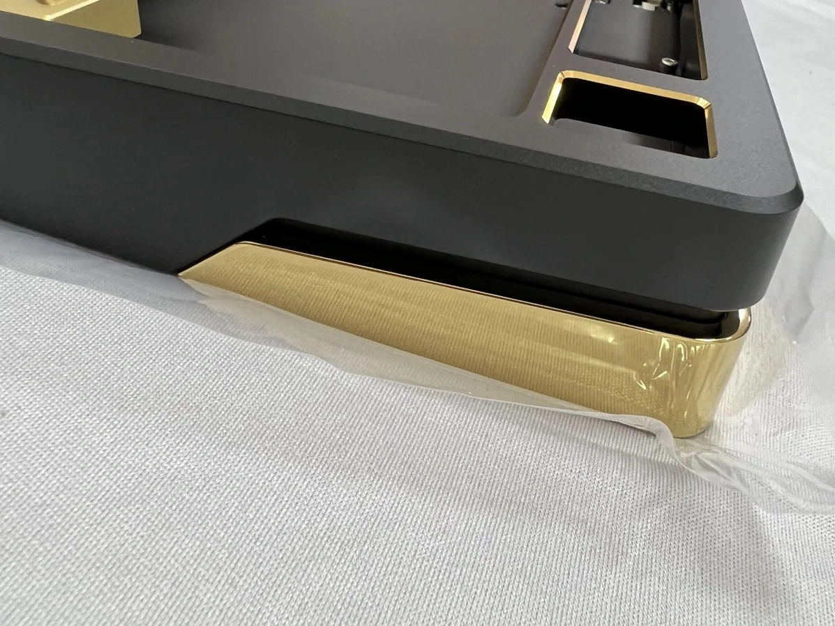
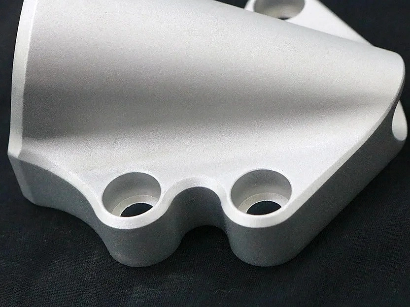
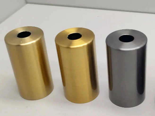
Neway’s Surface Treatment for Prototyping Parts includes processes like anodizing, coating, polishing, plating, and heat treatment. These treatments enhance material properties, improve durability, corrosion resistance, and surface finish, ensuring high-quality, functional prototypes suited for demanding applications.
Learn More
Thermal Coating
Learn More
As Machined
Learn More
Painting
Learn More
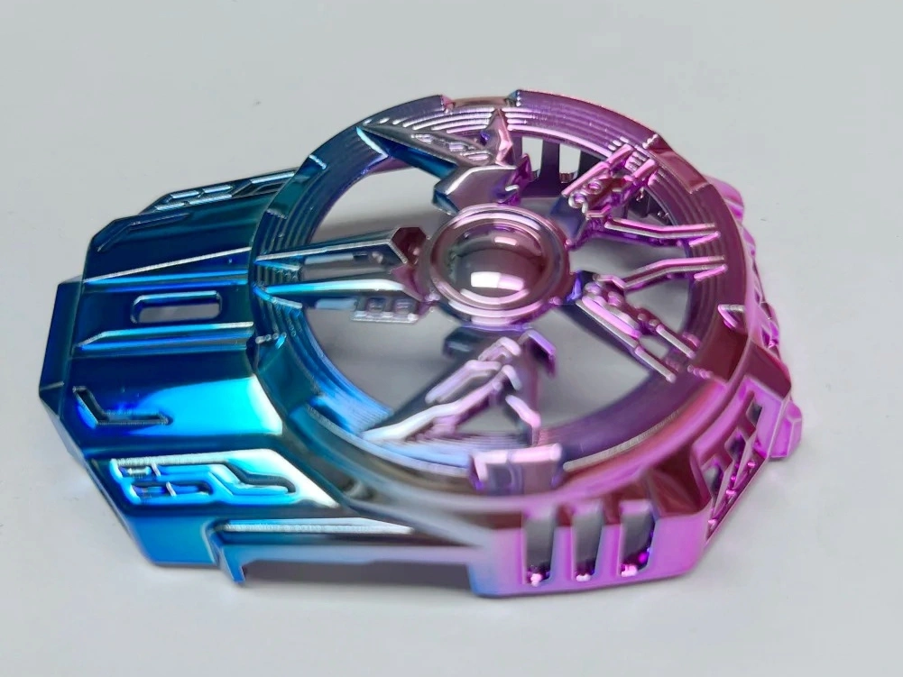
PVD (Physical Vapor Deposition)
Learn More
Sandblasting
Learn More
Electroplating
Learn More
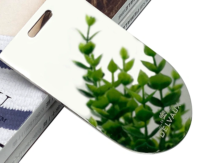
Polishing
Learn More
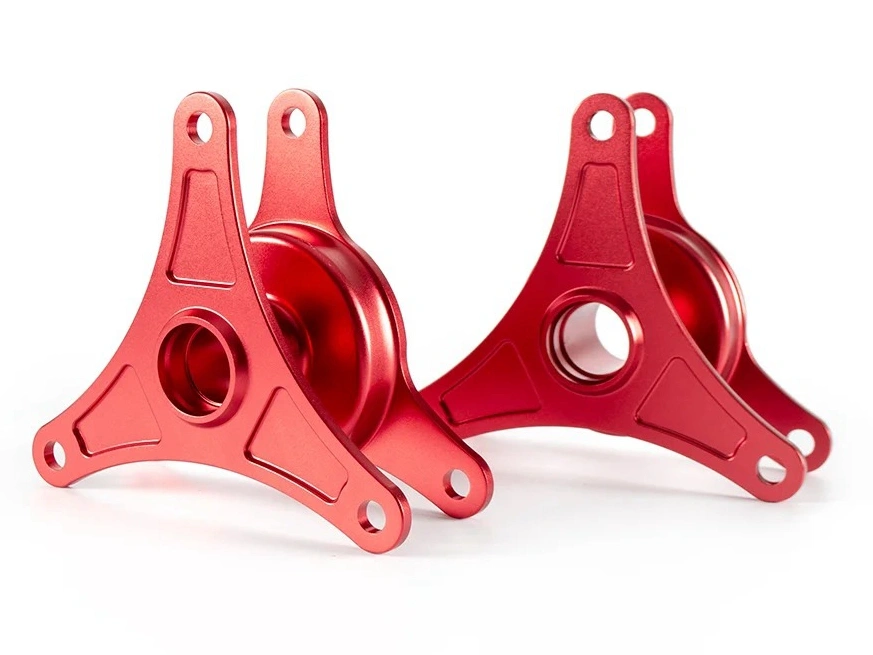
Anodizing
Learn More
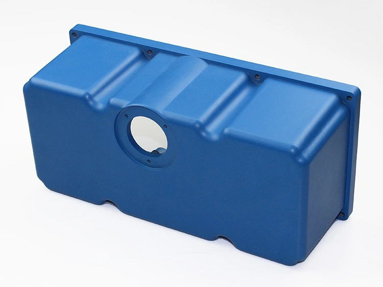
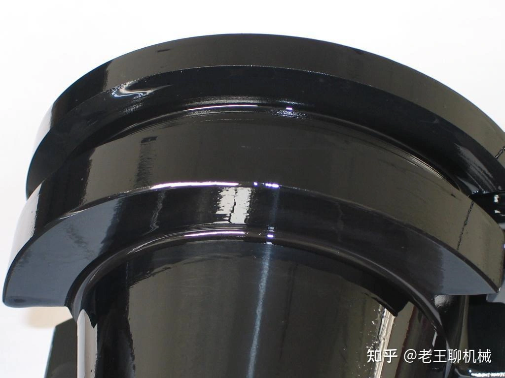
Powder Coating
Learn More
Electropolishing
Learn More
Passivation
Learn More
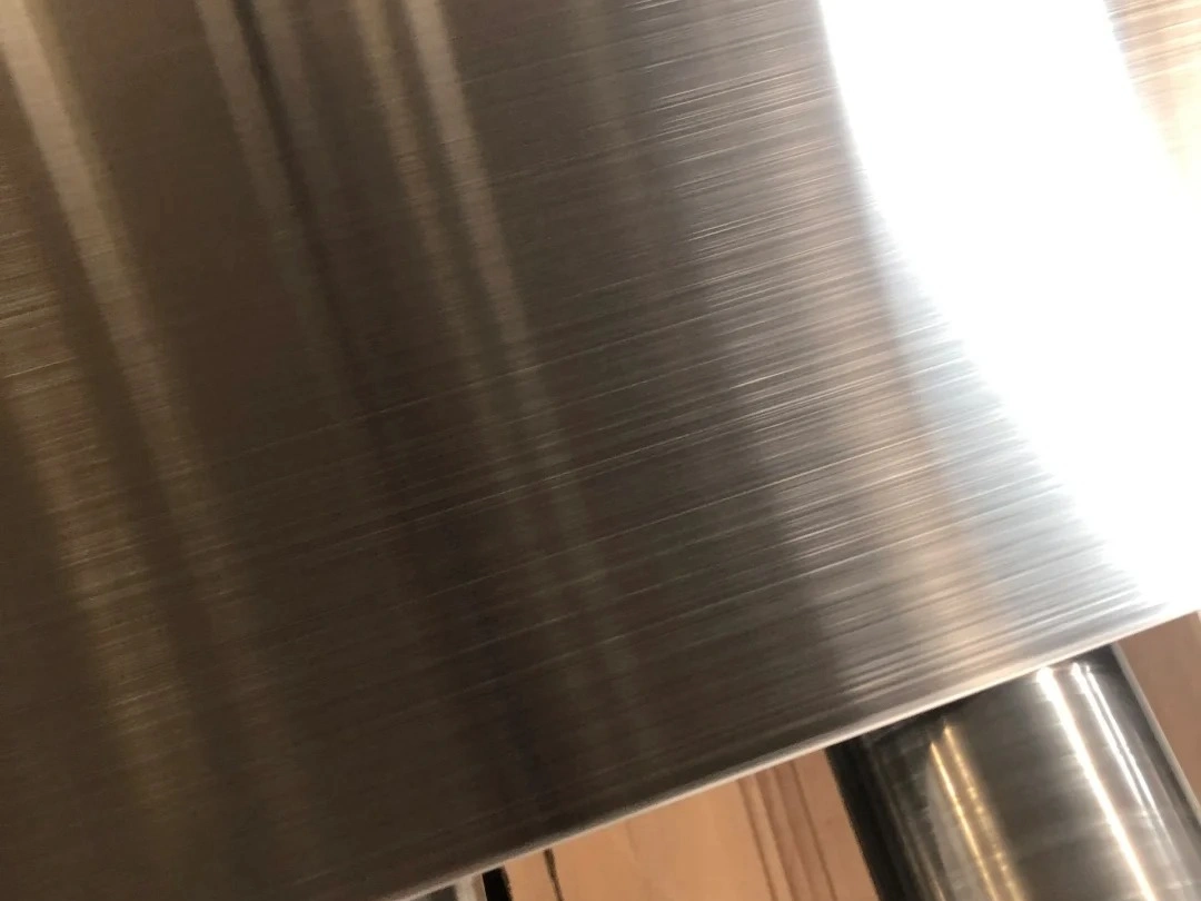
Brushing
Learn More
Black Oxide
Learn More
Heat Treatment
Learn More
Thermal Barrier Coating (TBC)
Learn More
Tumbling
Learn More
Alodine
Learn More
Chrome Plating
Learn More
Phosphating
Learn More
Nitriding
Learn More
Galvanizing
Learn More
UV Coating
Learn More
Lacquer Coating
Learn More
Teflon Coating
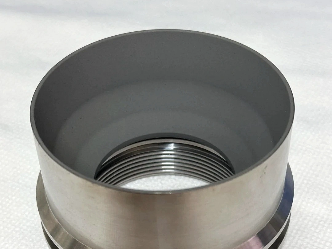
Machining Prototyping Case Study
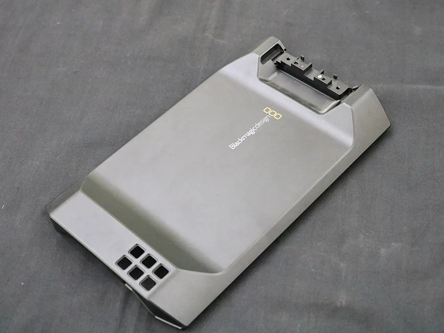
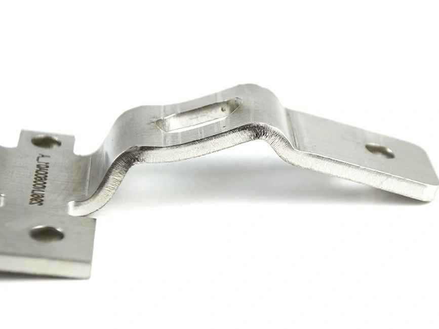
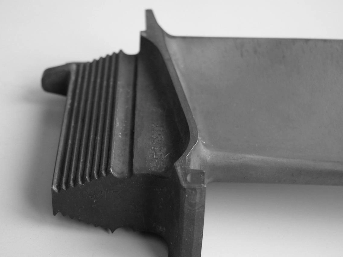
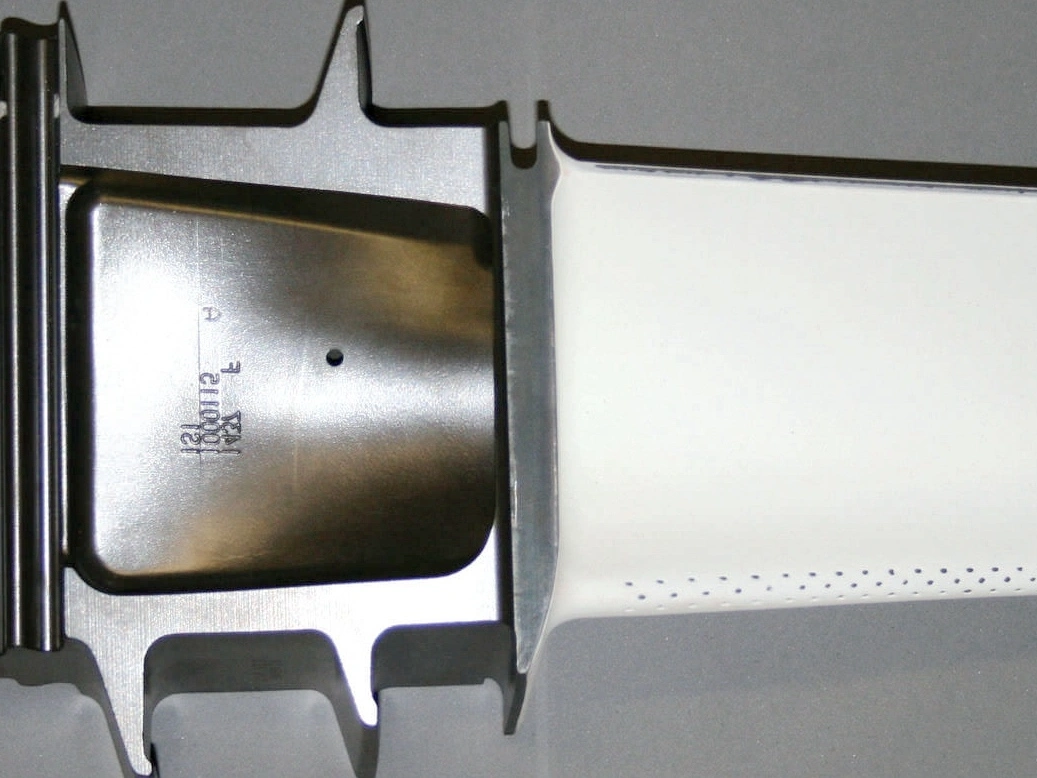
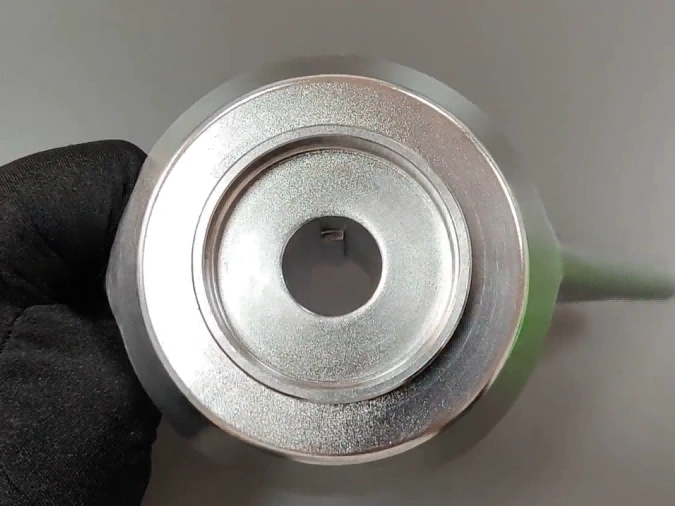
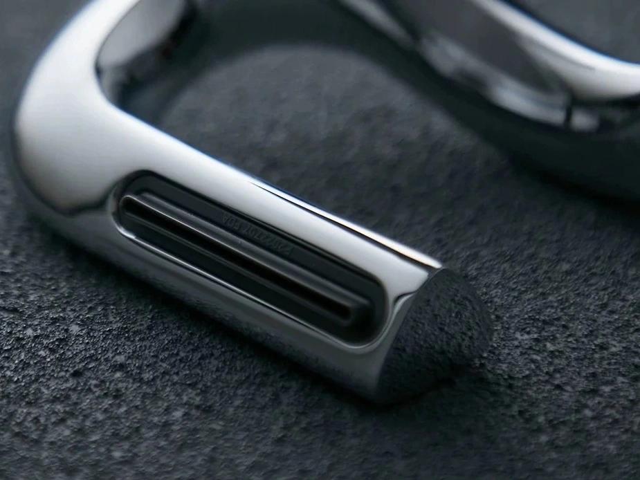
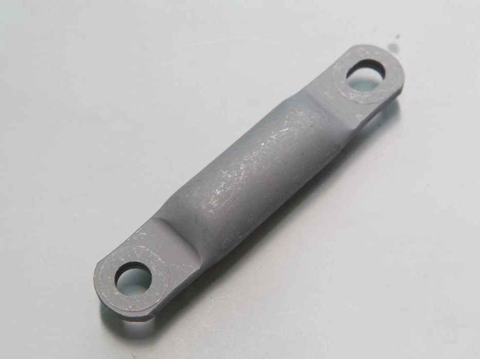
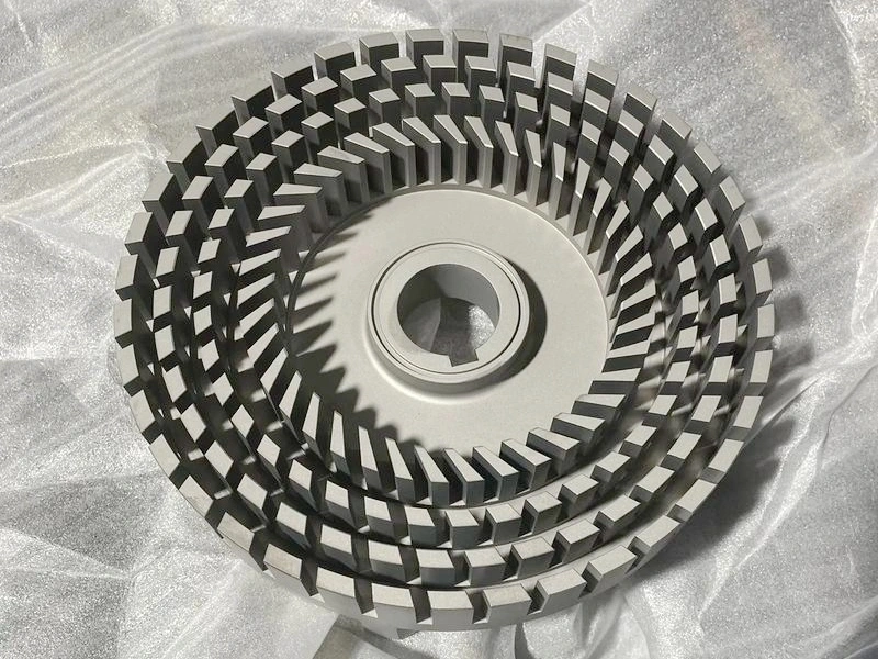
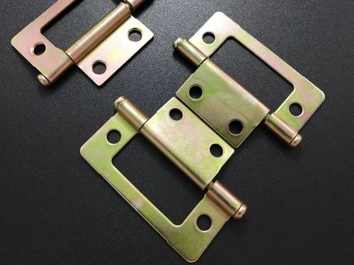
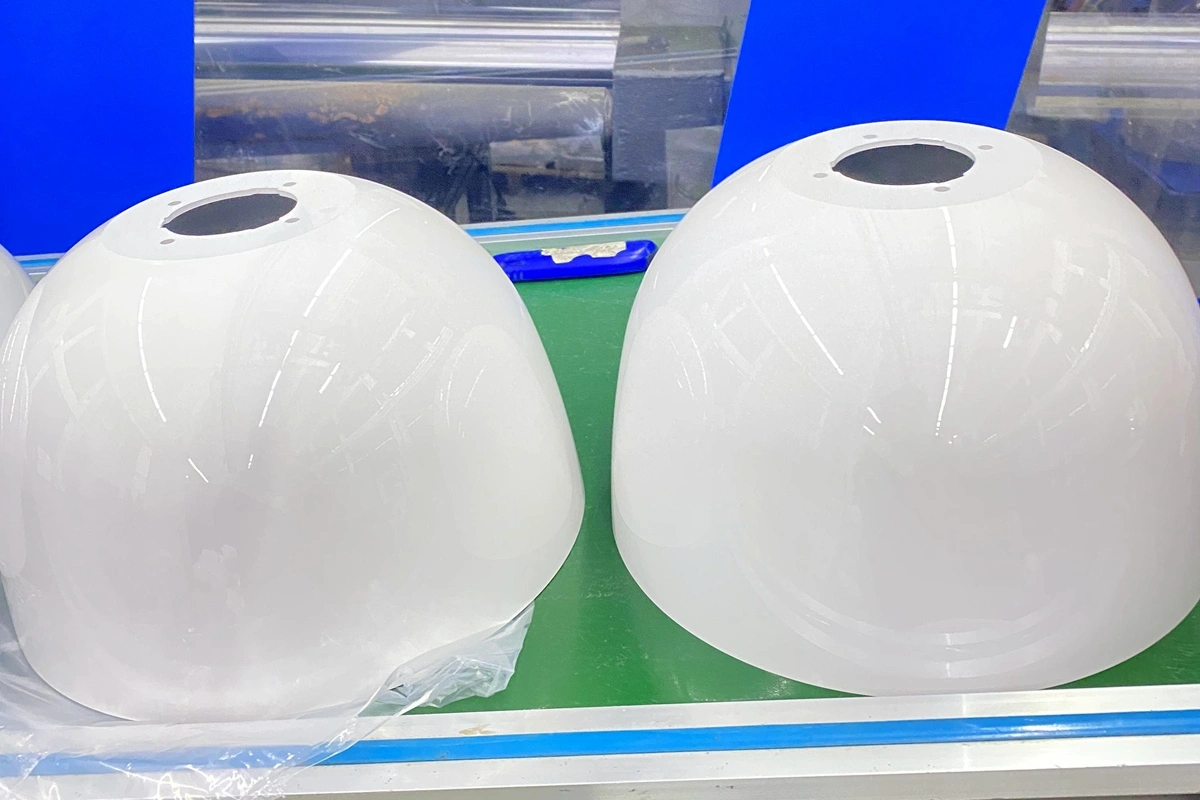
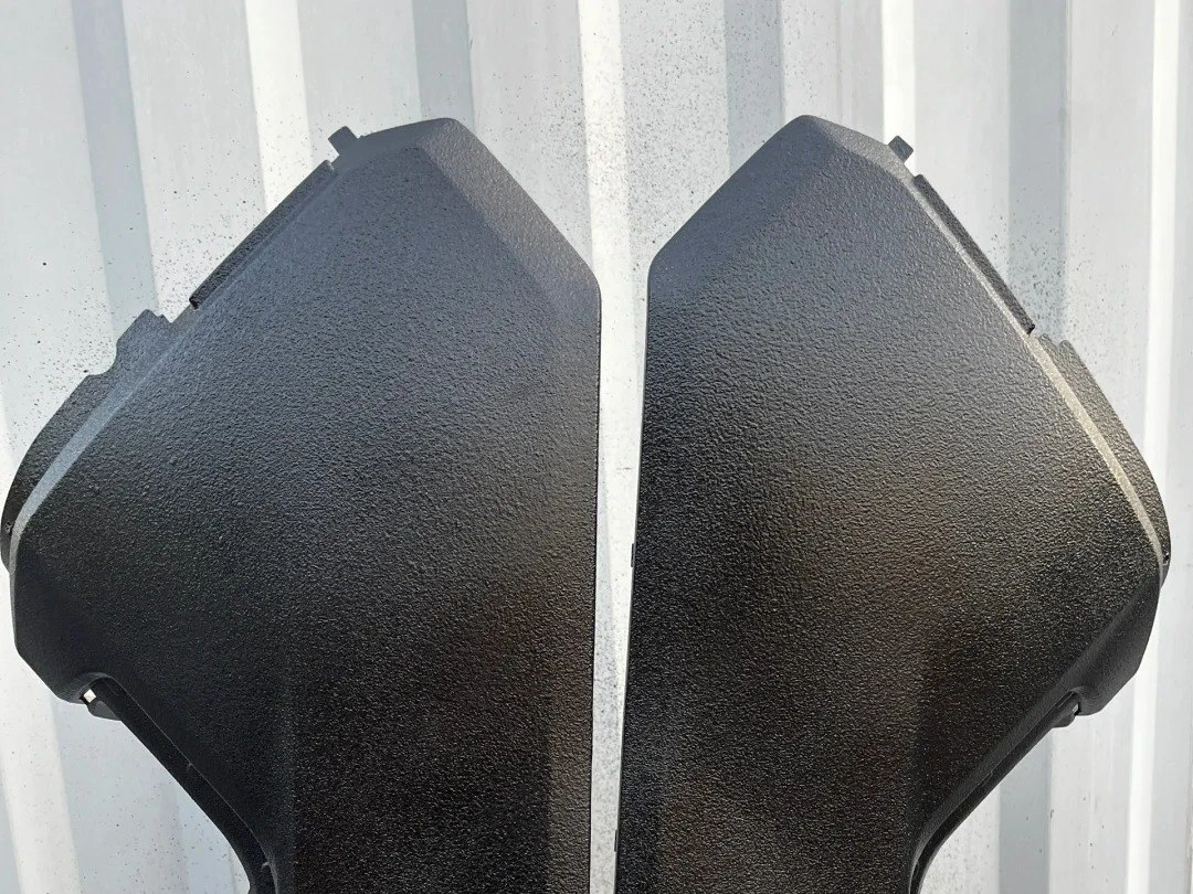
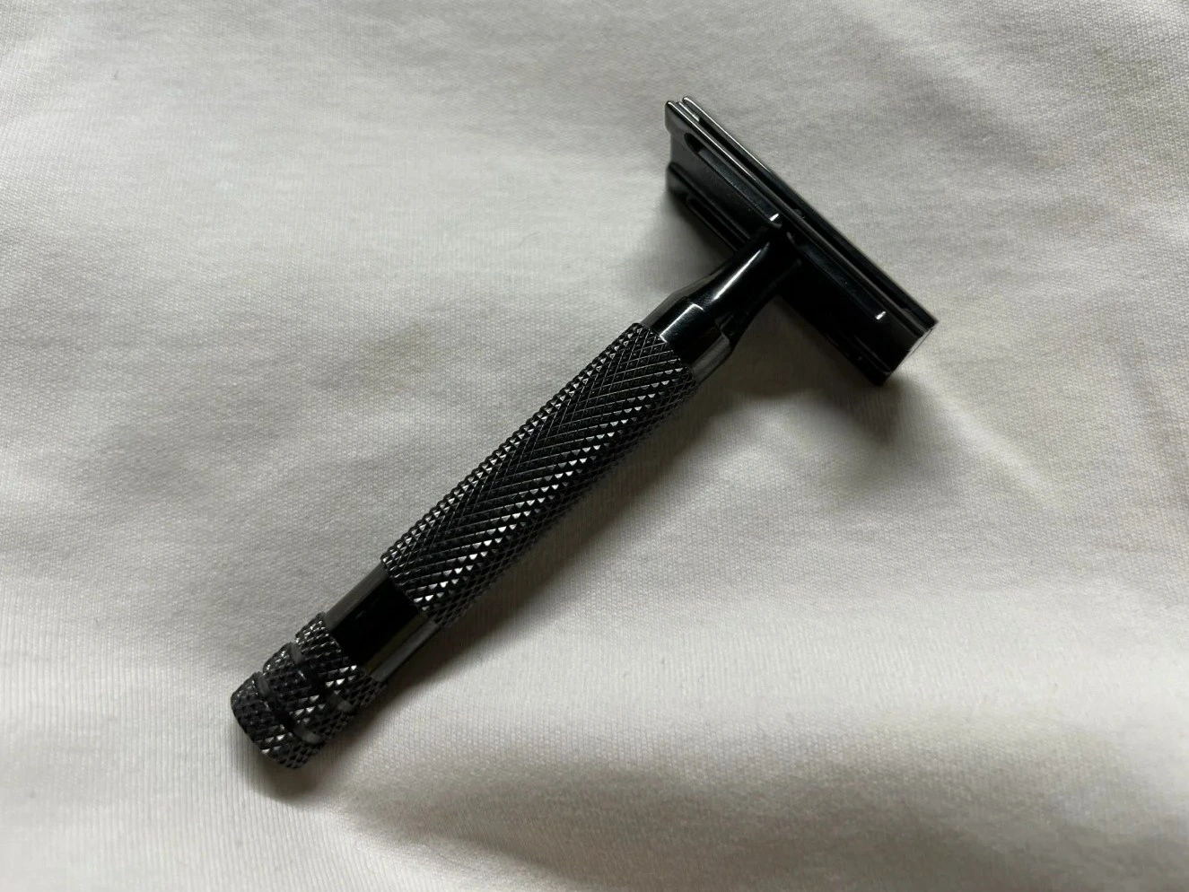
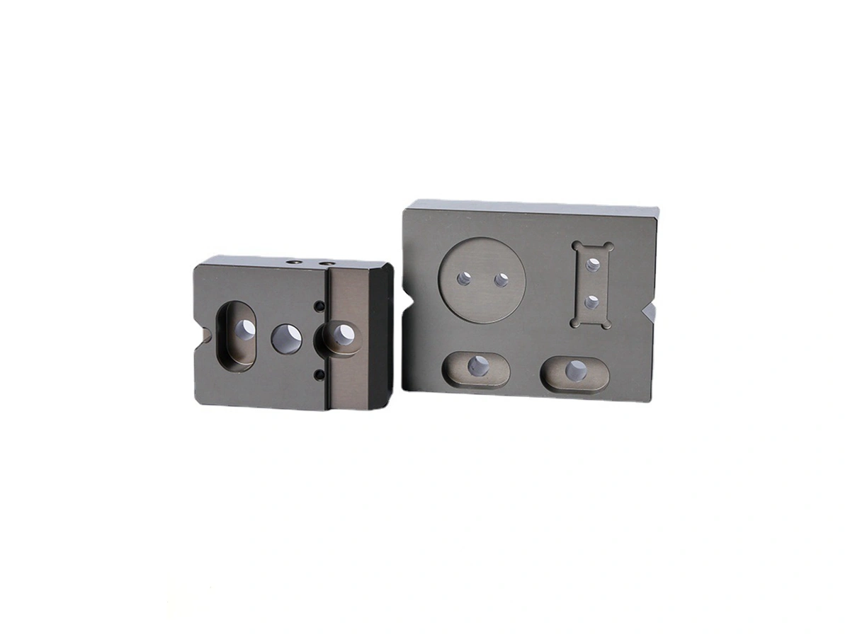
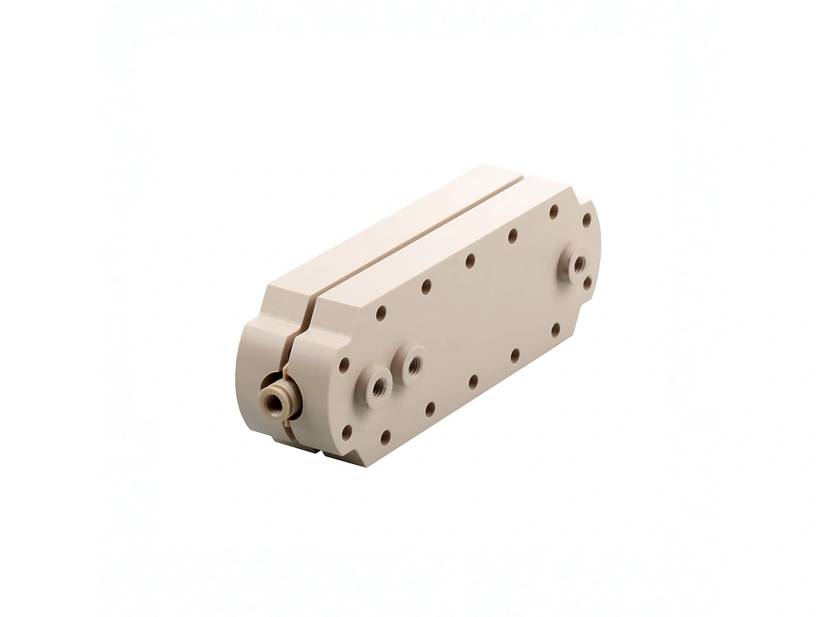
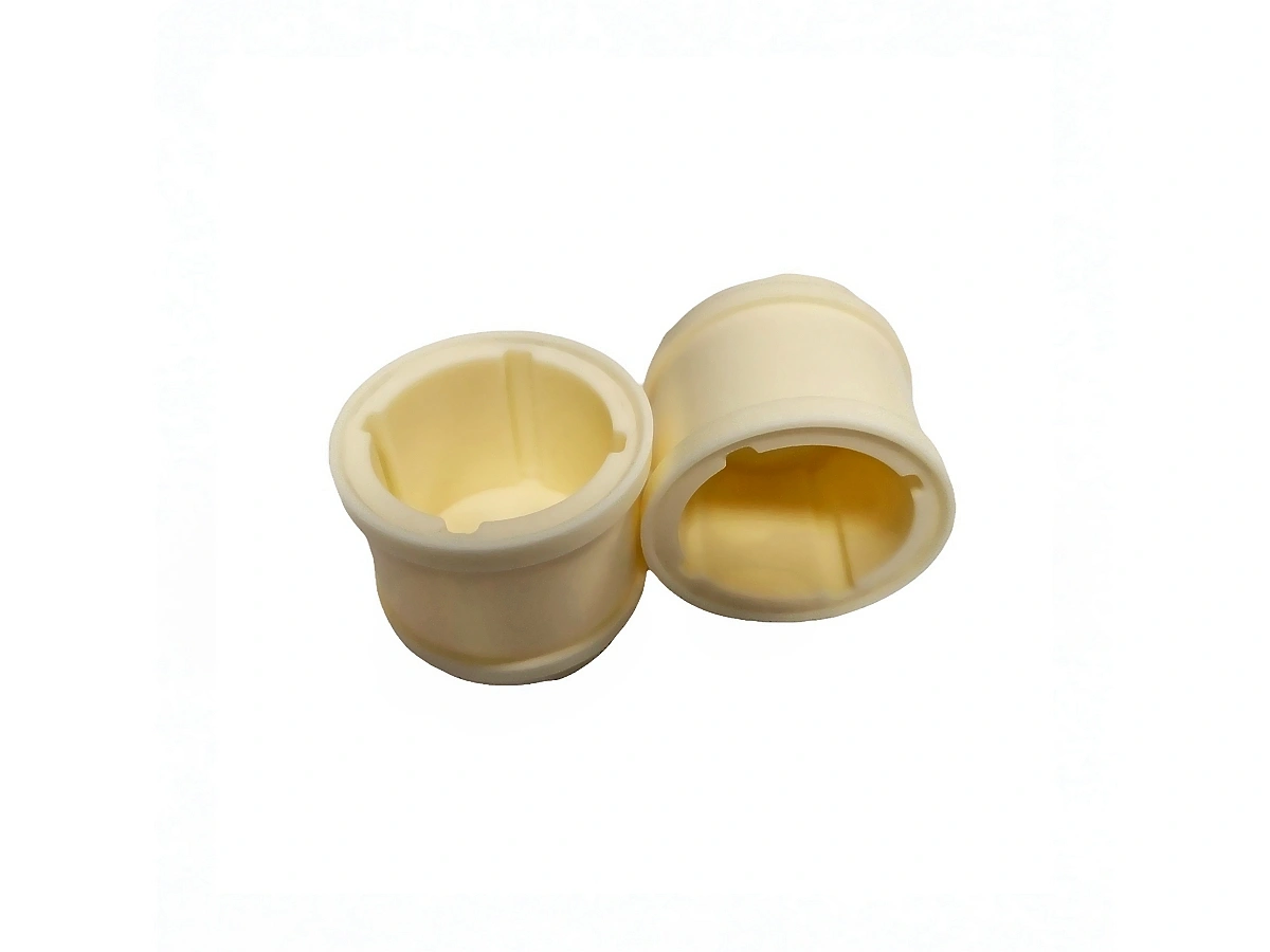
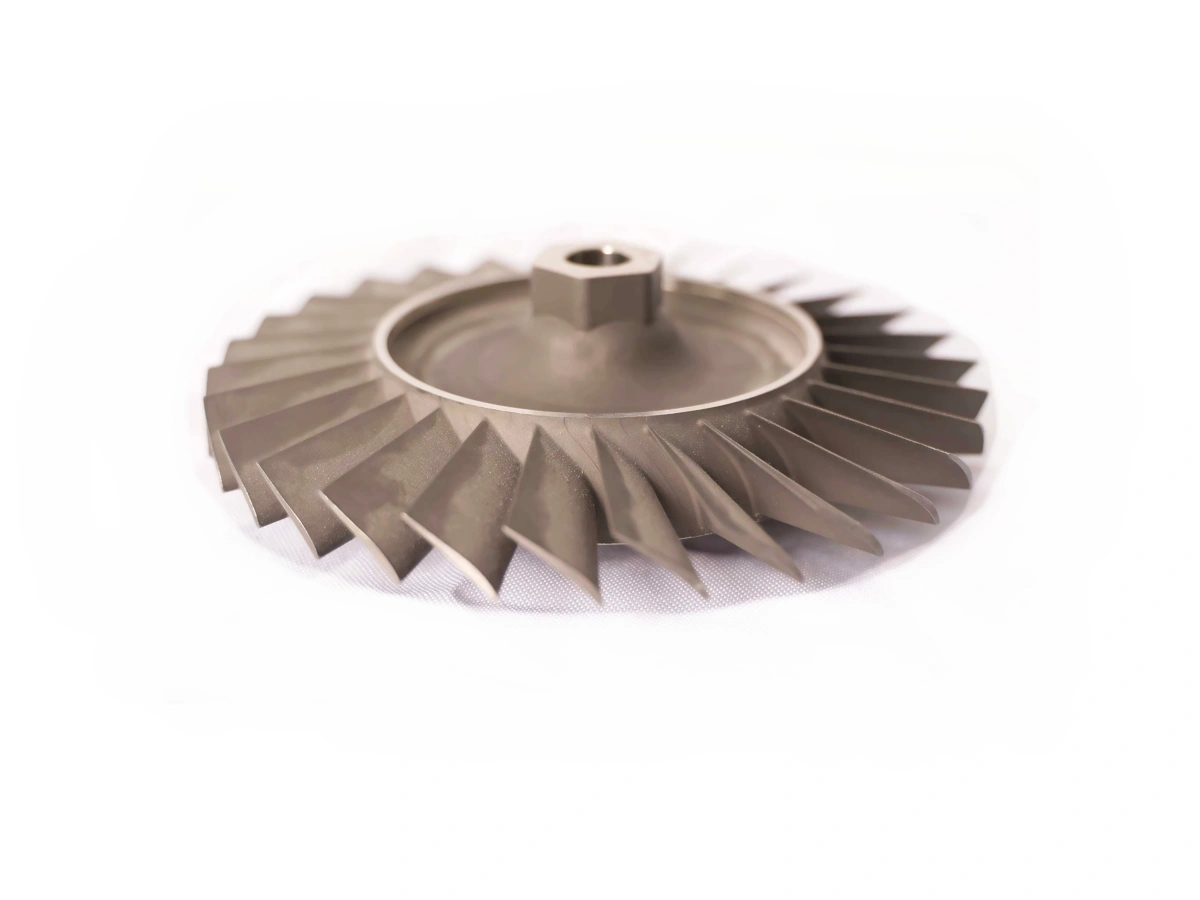
Neway's Machining Prototyping Case Study demonstrates successful use of Superalloy, Titanium, Aluminum, Copper, Brass, Bronze, Carbon Steel, Stainless Steel, Plastic, and Ceramic materials. We delivered precise, high-performance prototypes across diverse industries, meeting client specifications with exceptional quality and efficiency.
Let's Start A New Project Today
Suggestions for CNC Prototyping
CNC prototype design guidelines emphasize material selection, uniform wall thickness, achievable tolerances, and accessible features. Key principles include avoiding sharp corners, minimizing material removal, and ensuring proper hole design and symmetry to optimize machining efficiency, cost, and part quality.
Frequently Asked Questions
Explore Related Resources

Neway Precision Works Ltd.
No.3 Lefushan Industry West Road
Fenggang, Dongguan, China
ZIP 523000
Solutions
Copyright © 2026 Machining Precision Works Ltd.All Rights Reserved.