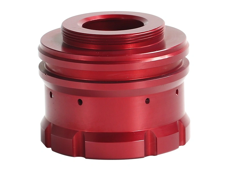
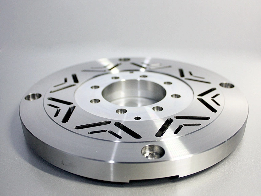
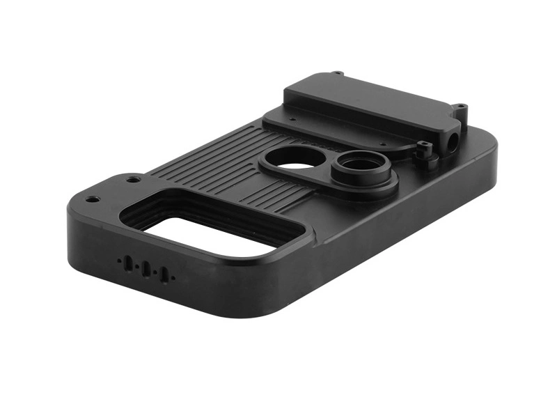
ISO-Certified CMM Quality Assurance for CNC Machined Components
Introduction to CMM Inspection in CNC Quality Assurance
ISO-certified CMM quality assurance means an ISO-controlled quality system uses calibrated, traceable CMM measurement methods to verify CNC machined components against drawings, datum schemes, tolerances, and release rules. A CMM does not create part accuracy by itself. It provides measurement evidence when the program, fixture, probe, environment, calibration, and acceptance criteria are controlled.
Manufacturers use coordinate measuring machines (CMMs) to collect controlled geometric data for holes, datums, profiles, positions, flatness, and compound surfaces. Under ISO 9001, CMM inspection belongs inside a documented quality workflow with calibrated equipment, approved programs, controlled records, and non-conformance reaction rules. The method is especially valuable for complex components produced by multi-axis CNC machining services.
A useful CMM plan should explain what the machine measures, what it cannot prove, which features require other gauges or NDT, and which records the buyer will receive. For a related shop-floor inspection perspective, review CMM inspection for CNC machined parts, which shows how simpler gauges may support quick checks before final CMM verification.
What Is a Coordinate Measuring Machine (CMM)?
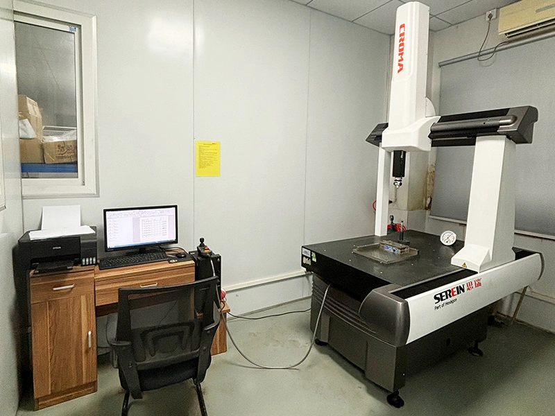
A coordinate measuring machine is an inspection system that measures the geometry of a machined component in a defined coordinate system. The CMM captures points, scans surfaces, or checks features against a drawing or CAD model. Its value depends on the datum setup, probe choice, program validation, environmental stability, and calibration status.
Working Principle and Configuration
A CMM uses a tactile or optical probing system to collect coordinates from selected points, surfaces, holes, slots, and profiles. Bridge-type machines are common for CNC components because the gantry can move across three linear axes. Tactile probes suit hard metal features and datum checks. Optical or laser methods may suit delicate surfaces, plastics, ceramics, or finished areas where contact force could distort the reading.
Modern CMM software can compare measured data with 3D CAD models, GD&T callouts, and inspection plans. Automated reporting reduces manual transcription errors, but the program still needs review and approval. The captured data can support FAIR packages, in-process verification, supplier audits, and root-cause analysis when the records identify the part number, revision, setup, probe, operator, and calibration status.
Types of CMM: Contact vs Non-Contact
CMMs are classified into two major types based on their probing methodology:
Contact CMMs use a mechanical stylus that touches the part surface. They are suitable for datum features, bores, planes, slots, and metal parts that can tolerate controlled probe contact.
Non-contact CMMs use optical systems, lasers, or vision sensors to measure features where contact force, surface finish, transparency, or fragile geometry can affect the result.
For complex geometries, multi-axis probe articulation can reduce part reorientation and improve access to angled features. It does not make a CMM inherently more accurate; measurement uncertainty still depends on the machine, probe configuration, calibration, environment, datum strategy, and program. Components produced by multi-axis machining may benefit from 5-axis CMM verification when the stylus can reach the required surfaces without unstable refixturing.
The correct CMM configuration should be selected from the feature, tolerance, material, surface condition, and required record. Buyers should ask which features will be measured by contact CMM, which by optical method, and which require a separate gauge or NDT process.
ISO 9001 & CMM: Establishing a Certified Quality System
ISO 9001 is a quality management system standard. It controls how requirements, processes, records, non-conformances, and improvements are managed. In CNC machining, ISO 9001 does not certify a dimension or guarantee a tolerance. It requires the supplier to define, perform, record, and control inspection activities such as CMM measurement.
Role of CMM in an ISO 9001-Compliant Workflow
In an ISO 9001-certified facility, CMM inspection should be connected to incoming inspection, process planning, first article approval, in-process checks, final inspection, and non-conformance control. The CMM bridges machining output and drawing intent only when the measurement plan follows the datum scheme and acceptance rule.
Each CMM program can generate digital measurement records that support compliance with specified tolerances. The record should show the measured feature, nominal value, actual value, deviation, tolerance, equipment, program revision, and pass/fail status. Combined with CNC machining prototyping, early dimensional validation can expose datum ambiguity, fixture movement, or machining drift before mass production. It does not remove the need for process control, but it gives the team evidence for corrective action.
Benefits of ISO-Certified CMM Programs
Integrating CMM into an ISO 9001-compliant system yields several operational and commercial benefits:
Improved Traceability: Every controlled CMM report can record timestamp, operator or program ID, equipment identity, calibration status, part revision, and inspection result.
Risk Reduction: Dimensional verification through CMM reduces release risk for aerospace, medical, automotive, and automation parts when the measured characteristics are tied to the drawing and sampling plan.
Customer Confidence: Buyers sourcing custom precision machining services often require inspection reports, calibration evidence, and ISO quality-system records before accepting production lots.
Combining an ISO-controlled quality system with CMM metrology helps reduce escapes, clarify acceptance decisions, and support process improvement. Buyers should still confirm which features are inspected by CMM and which are controlled by gauges, visual inspection, surface testing, or NDT.
Application of CMM in CNC Machined Components
Coordinate measuring machines (CMMs) are useful for inspecting complex geometries, tight tolerances, and critical interfaces in CNC machined components when the required features are physically accessible. Programmed measurement provides quantitative data and reduces operator-dependent variation, but uncertainty, fixturing, sampling, and feature access still limit what the result proves.
Aerospace CNC Parts
In aerospace components, some critical features may require 5-micron-class dimensional control under a defined datum scheme, stable temperature, suitable uncertainty ratio, and approved measurement method. CMM inspection can verify accessible bore diameters, position, flatness, profile, and form tolerances when the setup and program are validated. Inspection planning for aerospace CNC machined parts can assign channel openings, bearing-housing datums, and mounting-hole patterns to a CMM, while enclosed cooling passages require a specified borescope, flow test, computed tomography, or other suitable method.
A 5-axis CMM system can inspect angular features and deep cavities with fewer repositioning steps. That can improve repeatability when stylus access, collision risk, and fixture stability are reviewed before the program is released.
Medical-Grade Components
CMM inspection can validate accessible geometry on surgical-grade components such as titanium surgical implants, orthopedic plates, or spinal fixation systems. Freeform profiles may require scanning paths or dense point patterns chosen from the drawing tolerance and uncertainty target; thread form, surface texture, coating thickness, and biological performance require separate methods.
Validation of screw-hole position, thread geometry, profile tolerance, and mating surfaces supports functional compatibility in regulated applications. The final acceptance rule should come from the drawing, product specification, and customer quality plan.
Industrial & Automation Components
In high-volume automation systems, CMM inspection helps verify standard parts, such as custom dowel pins, motor spindles, and support bushings. For instance, components such as carbon steel clamping accessories used in automated fixtures require consistent bore alignment and perpendicularity—parameters that are ideally validated using a CMM system.
Dimensional verification during pilot production and final QC mitigates the risks of misaligned components in robotic systems and high-speed manufacturing lines.
Material-Specific Use Cases
CMM application is not limited to metals alone. It is also used to verify the dimensions of plastic and ceramic parts, especially when combined with plastic or ceramic CNC machining. Non-contact CMM systems, including laser or optical sensors, can reduce surface deformation risk on softer materials. Accuracy still depends on reflectivity, surface color, transparency, fixture support, and scan-to-CAD alignment.
Manufacturers can optimize inspection routines across diverse component categories by matching CMM capability to material properties and part geometry.
CMM Inspection Process: From Setup to Reporting
Effective CMM inspection depends on a structured workflow, not only on machine precision. A controlled process includes part setup, fixture alignment, measurement programming, data acquisition, result review, and report release. Each phase affects whether the measurement can be trusted.
Step 1: Part Setup and Fixture Alignment
Before measurement, the component must be clean, stable, and aligned to the correct datum scheme. Fixturing should support the part without bending thin walls or hiding critical features. In ISO 9001-controlled workflows, alignment procedures should define datum targets, fixture contact points, operator checks, and when a part must be rejected before measurement.
This phase also includes verifying part cleanliness and surface condition—critical for accurate results, especially in post-process inspections such as after anodizing or black oxide coating, where surface reflectivity may influence optical probe accuracy.
Step 2: Measurement Programming
Most modern CMMs operate from programs based on GD&T callouts, drawings, and 3D CAD files. The programmer defines features, point density, probe paths, datum alignment, tolerances, and report format. Simulation can reduce collision risk, but the program still needs validation against the drawing and a known good setup.
Offline programming is particularly efficient for high-mix, low-volume runs, which are common in CNC machining prototyping, enabling rapid deployment without interrupting active inspection schedules.
Step 3: Data Acquisition and Execution
Once the program is validated, the CMM executes the inspection using touch-trigger, scanning, or optical probes. Point count and cycle time depend on feature count, sampling density, probe changes, approach paths, temperature stabilization, and required uncertainty. Buyers should not compare CMM capability from point count or speed alone.
Features such as flatness, parallelism, cylindricity, profile, and hole position are compared with nominal values and tolerance zones. For multi-axis components such as aluminum robotic joints, the CMM plan should confirm angular offsets, compound surfaces, datum relationships, and any post-treatment dimensional shift.
Step 4: Reporting and Data Analysis
The final step is to review measured data and release an inspection report. The report should show deviations, pass/fail status, measured equipment, program revision, and statistical trends when applicable. FAIR documents should link CMM results to the ballooned drawing and customer validation requirements.
The inspection data can be integrated into quality control dashboards, contributing to feedback loops in PDCA (Plan-Do-Check-Act) cycles and long-term process improvement. This is especially important in certified precision machining environments, where defect prevention is prioritized over post-process correction.
Advantages of Using CMM for CNC Machined Part Inspection
Coordinate measuring machines (CMMs) offer unique advantages in inspecting complex CNC-machined components with the accuracy, consistency, and documentation required for demanding applications. Whether deployed in prototyping or mass production environments, the benefits of CMM-based inspection extend across technical, operational, and commercial domains.
High-Precision Dimensional Verification
Unlike simple gauges or manual calipers, CMMs can evaluate three-dimensional geometry, hole position, form error, and GD&T relationships in one controlled program. The stated resolution of a machine should not be confused with total measurement uncertainty. This distinction is critical in sectors requiring complex parts like superalloy CNC machined components, where multi-feature alignment and thermal distortion must be controlled within narrow tolerances.
Trend data from repeated CMM inspections can reveal tool wear or process drift before out-of-tolerance parts reach downstream operations when the sampling interval, reaction limits, and responsible reviewer are defined.
Enhanced Repeatability and Objectivity
Manual inspection methods can vary by operator, gauge pressure, interpretation, and recording practice. CMM inspection reduces subjectivity through programmed paths and standardized reports. Once a program is approved, it can be reused for future batches when the part revision, fixture, probe, and setup method remain the same.
This consistency is valuable for rotating shafts, engine-related parts, automation fixtures, and matched assemblies where small datum shifts can affect balance, fit, or motion.
Faster, Non-Destructive Inspection
Modern CMMs can reduce repeated manual setups when one controlled program measures several accessible features. Near-process checks may shorten feedback for parts produced by multi-axis machining, but cycle time, temperature stabilization, fixture loading, and queue capacity must be included in the inspection plan.
Non-contact optical probes can inspect soft, delicate, or finished surfaces with lower contact risk. They are useful after polishing, powder coating, or other treatments that require surface integrity.
Digital Documentation and Traceability
A controlled CMM system can store feature results, timestamps, equipment and program identity, probe qualification, and pass/fail status. These records support quality audits, supplier approvals, and regulated documentation only when access, revision, retention, and approval controls are defined. CMM data may be integrated into PDCA-based quality control systems to support root-cause analysis and corrective-action planning.
Access to this digital trail helps buyers review compliance evidence and reduces disputes about dimensional non-conformance. The report should still be checked against the drawing revision and agreed acceptance criteria.
Use Cases from Medical, Aerospace, and Industrial Projects
Practical examples show where CMM inspection adds value in ISO-controlled CNC operations. The following examples are engineering scenarios based on the linked part types. They should not be read as unverified Neway project results or guaranteed outcomes.
Medical: Titanium Surgical Implants with PVD Coating
Medical components require the geometry and surface condition specified by the drawing. For titanium surgical implants, a CMM or optical sensor can evaluate accessible profiles, hole positions, and insertion-fit geometry before and after PVD. Coating thickness itself should be verified by a method specified for the coating and substrate; the CMM only shows any resulting change in accessible overall geometry.
This two-stage inspection logic supports dimensional review around finishing, while a separate validated method checks coating thickness. Biocompatibility, regulatory release, and ISO 13485 compliance require additional validated processes beyond CMM measurement.
Aerospace: Multi-Axis Machined Robotic Joints
Consider aluminum 6061 robotic joints produced with multi-axis CNC machining and anodizing. An inspection plan could verify accessible flatness, perpendicularity, and position relationships across several orientations because those features affect joint alignment and motion. The drawing must define the datums, coating allowance, feature tolerances, and whether inspection occurs before or after anodizing.
CMM comparison before and after anodizing can reveal dimensional shift from coating thickness, masking, or thermal exposure. The correction should be handled through drawing allowance, fixture review, and approved program changes.
Industrial Automation: Carbon Steel Clamping Accessories
In automation, CNC machined carbon steel clamping accessories are used in fixture assemblies where repeatability is critical. These parts require strict control over bore diameter, parallelism, and alignment with multiple mounting points.
Programmable CMM routines can support full inspection of selected critical features when the customer requires it. Integrating CMM data into SPC dashboards helps identify drift, but any improvement in rework, lead time, or yield must be proven from actual production records.
Compliance with ISO 9001 and Global Standards in CMM Practice
For regulated or high-spec CNC components, CMM practice must fit the applicable quality system and customer contract. ISO 9001:2015 sets the general QMS framework. AS9100, ISO 13485, or IATF 16949 may add industry-specific controls when the customer or product scope requires them.
ISO 9001 as the Quality Framework Backbone
Under ISO 9001, CMM inspection can support clause 8.5.1 on controlled production and clause 8.6 on release of products and services. These clauses require evidence that defined requirements are met before release. CMM reports can provide that evidence when the measurement method is controlled.
Buyers considering suppliers such as Neway Precision should ask for the applicable certificate scope, CMM calibration status, program revision controls, sample report, and non-conformance workflow. A supplier should claim traceability or audit readiness only to the extent supported by controlled records for the quoted part.
Calibration and Maintenance per ISO 17025
CMM equipment used in an ISO 9001-controlled environment should have traceable calibration and routine verification. ISO/IEC 17025 applies to the competence of testing and calibration laboratories; it does not certify the CMM or the machining process. Calibration results should establish an unbroken traceability chain to SI units through a competent provider. Reference spheres, step gauges, or calibrated length standards can support interim system checks.
Routine maintenance, documented probe qualification, environmental checks, and software or program version control should be defined for CMM use within CNC machining services environments. These controls reduce avoidable variation during repeated inspection of components such as SUS304 medical fasteners, but the buyer should still review uncertainty, sampling, and the released report for the actual lot.
Alignment with Customer-Specific QA Protocols
Customer contracts may require FAIR (First Article Inspection Reports), PPAP (Production Part Approval Process), or detailed, ballooned drawings linked to measurement records. Validated CMM software can export dimension-by-dimension data for these formats, but a quality representative must verify feature mapping, drawing revision, and acceptance status before release.
In such contexts, the CMM is both a metrology tool and a compliance evidence source. It helps connect the drawing, measurement result, customer format, corrective action, and final release record.
Integrating CMM with Other CNC Inspection Technologies
Coordinate measuring machines remain a core method for dimensional verification in CNC machining, but they do not inspect every risk. Complementary technologies can be needed for freeform surfaces, internal defects, surface texture, coating thickness, hardness, or rapid shop-floor screening.
3D Scanning for Freeform Surface Verification
When dealing with complex organic shapes or surfaces without clear data references, 3D scanning measurement can complement CMM inspection. Structured light or laser scanners generate high-resolution point clouds, which are compared to the CAD model to detect warping, shrinkage, or over-machining.
This is useful for plastics, castings, additive features, and composite-like geometries where cooling, stress relief, or finishing can change broad surfaces. Scanning highlights surface deviation quickly, while CMM can validate the most critical datum-linked dimensions.
X-ray and Ultrasonic Testing for Internal Features
In applications where internal defects must be detected, such as in high-precision industrial tools or deep-bored shafts, contact-based CMM inspection alone is insufficient. That’s where non-destructive testing (NDT) technologies, such as X-ray inspection and ultrasonic testing, come into play.
Radiographic methods can reveal density-related discontinuities such as voids or porosity when material, thickness, orientation, resolution, and acceptance criteria are suitable. Ultrasonic testing can evaluate wall thickness, bond quality, or internal discontinuities when geometry, coupling, calibration blocks, and procedures permit. Used with CMM, these technologies separate external dimensional evidence from internal-condition evidence.
Contour and Height Gauges for Rapid Shop-Floor Checks
Tools such as height gauges and contour measuring systems provide rapid assessments of specific features, including step heights, edge profiles, and concentricity, for fast, in-process verification. These are often used before or alongside final CMM inspections to catch outliers early.
Combining CMM inspection with faster shop-floor metrology helps detect outliers earlier and reserve CMM time for datum-critical features. Buyers should ask which checks are used for process control and which checks are used for final acceptance.
Conclusion: The Future of CNC Inspection with ISO-Certified CMM Systems
ISO-controlled CMM inspection will remain important in CNC quality assurance because buyers need traceable evidence, not only machined parts. CMM systems can support statistical process control, digital quality records, and customer documentation when the equipment, program, fixture, and acceptance rule are controlled.
Manufacturers are integrating CMMs with MES systems, closed-loop feedback, and digital part records to shorten response time. CMM data can guide upstream decisions such as toolpath review, offset control, fixture correction, and anomaly investigation when engineering approval rules are clear.
By embedding CMM inspection within a broader CNC machining service ecosystem with automation, real-time data, and layered metrology, CNC suppliers can uphold ISO 9001 principles while keeping measurement evidence tied to the actual drawing and production lot.
Whether inspecting aluminum robotic components, titanium implants, or automotive steel shafts, CMM systems should validate the dimensions, datum relationships, and inspection records that matter for the buyer’s release decision.