CNC Milling for Aerospace, Medical, Automotive, and Industrial Applications
CNC milling serves aerospace, medical, automotive, and industrial applications when accessible geometry, material condition, setup strategy, and inspection planning are matched to the part's failure risk. The process can machine pockets, contoured surfaces, hole patterns, threads, sealing faces, datum planes, and structural features directly from digital part data. Its shared advantage is control of related features; its limitation is that each sector defines an unacceptable failure differently. A buyer should identify the application, drawing revision, material condition, critical features, finish state, quantity, and required inspection evidence before the supplier plans the route.
The engineering priority changes with the consequence of failure. An aerospace bracket may be rejected for datum shift or damaged surface integrity, while a medical component may fail because of a burr, inaccessible residue trap, or altered functional surface. An automotive housing may leak or mislocate a sensor, and an industrial mount may create misalignment, wear, or downtime. Inspection depth should therefore follow feature function, failure consequence, and production stage rather than the industry name alone. The RFQ should also distinguish a fit-check prototype, a pilot lot, and repeat production because each stage needs different evidence.
Why CNC Milling Is Used Across Multiple High-Value Industries
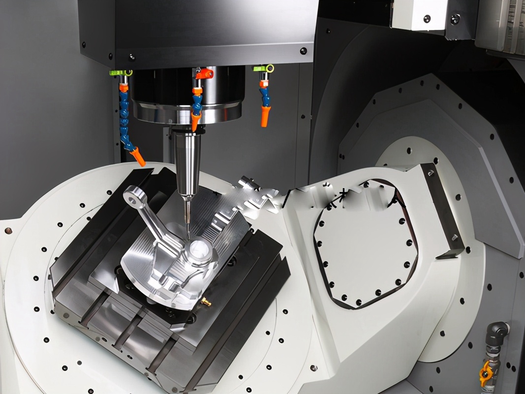
CNC milling is used across high-value industries because it combines geometric access with measurable control of feature relationships. Prismatic surfaces, angled faces, deep pockets, thin walls, bosses, slots, and multi-face parts can be produced when the route accounts for datums, workholding, tool reach, cutting load, and inspection access. Aluminum, stainless steel, titanium, copper alloys, engineering plastics, and high-temperature alloys can all be milled, but the material grade and condition change the route. The meaningful result is not machine motion by itself. It is a bore, pad, slot, and mounting face that remain functionally related after cutting, unclamping, deburring, and finishing.
Milling also adapts across the product lifecycle. It can support early samples, engineering validation, bridge production, low-volume functional parts, and recurring custom production without the same tooling commitment as molding, casting, or stamping. Early prototypes mainly test geometry and assembly access. Pilot lots should expose setup sensitivity, tool-wear effects, inspection repeatability, and finish interactions. Repeat production needs a defined revision, stable datum route, inspection frequency, and change-notification trigger. When geometry is frozen and demand is high, a tooling-based process may become more economical, so buyers should compare total program risk rather than only unit price. That lifecycle logic is closely tied to Prototyping, Low Volume Manufacturing, and Mass Production.
What Aerospace Applications Demand from CNC Milling
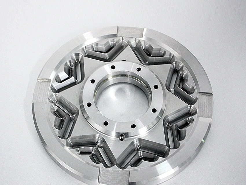
Aerospace applications demand CNC milling routes that protect datum relationships, low-mass geometry, surface integrity, and inspection traceability under the specified service conditions. Thin walls, lightening pockets, multi-surface interfaces, and contour-controlled features can move as residual stress is released or as clamp load is removed. A feature may pass a local size check yet fail position, flatness, or profile relative to the drawing datum system. Aerospace sourcing should therefore identify the load-bearing and assembly interfaces, not treat every dimension as equally critical.
Cutting heat, tool deflection, tool wear, burr formation, and unclamping movement can all change acceptance. Aluminum alloys often support lightweight structures, while titanium and high-temperature alloys may be selected for strength, corrosion, or temperature exposure; the exact grade and condition must be stated. The route should preserve finish allowance on critical faces, define when datum features are established, and inspect distortion after the part is released from workholding. An aerospace RFQ should state the applicable drawing standard, material specification, revision, critical datums, surface requirements, traceability scope, and requested dimensional report. Multi-face or advanced-axis strategies may reduce re-clamping, but fewer setups do not guarantee conformity. Aerospace-focused use cases are strongly linked to Aerospace and Aviation, aerospace machining requirements, and 5 Axis CNC Milling.
Typical Aerospace CNC Milled Parts
Part Type | Typical Material | Main Requirement | Process Control and Validation |
|---|---|---|---|
Structural brackets | High-strength aluminum or titanium | Low mass, stable datums, and stiffness | Control pocketing and clamp load, then check critical datums after unclamping. |
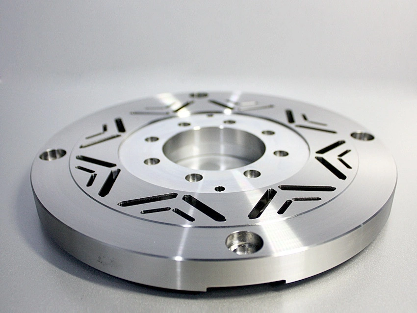
Interface plates | Aluminum or stainless steel | Flatness, hole position, and assembly reference | Measure the pattern from the specified datum system and verify mating-face condition. |
Thermal and airframe details | Aluminum alloys | Lightweight geometry and repeatable fit | Reserve finish allowance and confirm released-part geometry at the stated temperature. |
Engine-adjacent hardware | Titanium or high-temperature alloy | Strength, heat exposure, and surface integrity | Use material-specific tool controls and inspect the specified surface and edge zones. |
How CNC Milling Supports Medical Applications
CNC milling supports medical applications by producing compact functional geometry with controlled edges, inspectable interfaces, and surfaces that can be finished for the specified device use. Medical instruments, device components, alignment fixtures, probe supports, and implant-adjacent hardware may contain small holes, slots, contact faces, passages, and motion interfaces. A burr, sharp transition, residue trap, or altered surface can matter more than a nonfunctional outer dimension. Machining alone does not establish biocompatibility, cleanliness, or sterilization suitability; those requirements belong to the applicable device specification and validated downstream process.
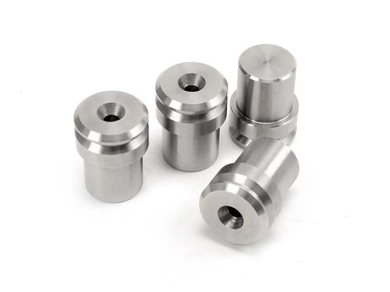
Stainless steel may be selected for corrosion resistance and cleanability, titanium for strength-to-weight needs and specified medical material applications, and high-performance plastics for insulation, low mass, or low friction. The exact grade, stock condition, and allowed manufacturing residues still control the machining plan. For a U.S. medical device program, the device manufacturer determines applicable supplier controls under its quality system. Since February 2, 2026, FDA's Quality Management System Regulation has been in effect with ISO 13485:2016 incorporated by reference, but that does not make every prototype or machined item a finished regulated device. Buyers should identify patient-contact or fluid-contact zones, edge requirements, cleaning state, finish sequence, inspection evidence, and whether the order is a fit check, functional validation lot, or controlled production component. Relevant references include Medical Device, high-precision CNC machining for surgical probes, and CNC milling of stainless steel medical components.
Medical CNC Milling Focus Areas
Medical Requirement | Machining Priority | Typical Material | Control and Acceptance Check |
|---|---|---|---|
Cleanable surface zone | Finish, burr removal, and residue control | Stainless steel | Define the zone and inspect edge and surface condition after the specified cleaning step. |
Miniature functional geometry | Tool access, datum control, and edge integrity | Titanium or stainless steel | Measure the functional interface with a method suited to its size and accessibility. |
Lightweight instrument structure | Thin-wall stability and grip geometry | Aluminum or titanium | Check released-part shape and critical interfaces after deburring and finishing. |
Insulating or low-friction part | Polymer clamping and thermal stability | Engineering plastics | Condition the part as specified before measuring dimensions sensitive to temperature. |
Why Automotive Programs Rely on CNC Milling
Automotive programs rely on CNC milling because it can move a functional part from design iteration through pilot supply while preserving the interfaces that affect assembly and vehicle testing. Housings, brackets, adapters, suspension interfaces, sensor mounts, powertrain details, and validation fixtures can be made before dedicated tooling is ready. The critical failure is rarely a generic lack of precision. A gasket face may leak, a sensor reference may shift, a threaded hole may lose torque capacity, or a bore pattern may prevent assembly. The drawing and inspection plan should focus on those functions.
Automotive sourcing usually applies stronger cycle-time and unit-cost pressure than aerospace or medical work, so critical and noncritical features need clear separation. Aluminum is common for lightweight housings and brackets, while carbon steels and stainless steels may be selected for load, wear, corrosion, or thread durability. Prototype parts should confirm packaging, fit, and test access. Pilot lots should confirm setup repeatability, finishing effects, and the inspection method intended for recurring supply. Repeat production should define drawing revision, sampling or report requirements, material traceability, and notification rules for process, fixture, tool, or supplier changes. The RFQ should state whether the part is for prototype testing, a pilot build, service replacement, or recurring production. Automotive-focused content is closely related to Automotive, high-quality CNC machined automotive parts, and precision machining for engine components.
Industrial Applications Where CNC Milling Delivers the Most Value
Industrial applications gain the most value from CNC milling when custom parts must assemble, seal, guide motion, carry load, and remain serviceable without dedicated tooling. Valve bodies, pump housings, actuator parts, automation brackets, guide elements, fixture plates, base structures, enclosures, and machine hardware often combine structural, corrosion, wear, and alignment requirements. The consequence of failure may be leakage, premature bearing or seal wear, difficult maintenance, lost calibration, or machine downtime. Buyers should therefore define the operating interface and service environment rather than relying on a broad industrial tolerance note.
Industrial parts frequently combine pockets, tapped holes, bores, sealing lands, alignment faces, and mounting features on one component. The process plan should connect the datum route with deburring, coating, assembly access, and any functional test. A fluid component may need a specified pressure or leak test after its final finish, while a mount may need a mating-part or gauge check that represents assembly. A threaded feature may require both dimensional verification and a defined thread acceptance method. RFQs should identify wear faces, seal type, fluid or chemical exposure, load direction, maintenance access, finish exclusions, and the inspection record needed for spare or repeat orders. This industry logic is strongly aligned with Industrial Equipment, custom CNC machining for industrial valves, and precision CNC machined industrial machinery components.
Common Industrial CNC Milled Components
Component Type | Main Functional Need | Material Direction | Control and Functional Check |
|---|---|---|---|
Valve and fluid hardware | Sealing, port alignment, and thread reliability | Stainless steel, brass, or aluminum | Inspect bores and sealing lands, then apply the specified leak or pressure test. |
Machine brackets and mounts | Rigidity, flatness, and positional accuracy | Steel or aluminum | Verify reference faces and hole patterns with the intended assembly datum. |
Automation modules | Assembly repeatability and sensor alignment | Aluminum or engineering plastics | Check actuator, guide, or sensor interfaces using the specified gauge or mating part. |
Pump and housing details | Interface quality, sealing, and service durability | Stainless steel or aluminum | Confirm datum relationships and final-finish sealing condition before release. |
Materials Used in CNC Milling for Different Industries
Materials used in CNC milling differ by industry because grade, heat treatment, temper, stock form, and service condition change cutting force, heat flow, burr formation, tool wear, clamping risk, distortion, and surface integrity. Aluminum can support low-mass structures and efficient stock removal. Stainless steel can serve corrosion-resistant and cleanable components. Titanium can support high strength-to-weight applications when heat and tool loading are controlled. Copper alloys may serve electrical, thermal, or fitting functions, while engineering plastics can provide insulation, low friction, or low mass. High-temperature alloys are selected for service requirements that ordinary alloys cannot meet, not simply because they are considered premium materials.
The best material is the documented grade and condition that satisfies service requirements while remaining practical for the geometry, quantity, finish, and inspection route. A family name such as aluminum, stainless steel, titanium, or plastic is not enough for quotation. The RFQ should provide the material specification, grade, temper or heat treatment, stock-form restrictions, certification needs, finish, service environment, and critical features. A thin aluminum housing, stainless valve plate, titanium bracket, and polymer guide block require different workholding, tool, burr, thermal, and measurement decisions. Proposed substitutions should be reviewed against function and downstream processing before purchase approval. This decision logic is closely connected to best materials for CNC milling and how to select the right metal for custom parts.
How Tolerance and Inspection Vary by Industry
Tolerance and inspection should vary with feature function, failure consequence, material behavior, production stage, and contractual evidence requirements rather than with an industry label alone. Aerospace programs may emphasize profile, datum relationships, released-part geometry, and traceable reports. Medical parts may emphasize small interfaces, controlled edges, surface zones, and downstream-process state. Automotive parts may prioritize repeatable functional features under cost and cycle constraints. Industrial components may focus on assembly, sealing, wear, and service checks. ASME Y14.5-2018 (R2024) and ISO 1101:2017 provide rules for expressing and interpreting geometric requirements within their respective drawing systems; neither standard by itself proves that a supplier can hold a stated tolerance.
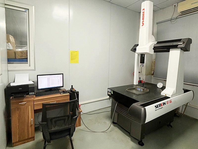
Inspection methods must match the specified characteristic. Calipers or micrometers may suit accessible size features, while a height gauge, coordinate measuring machine, form instrument, surface-texture instrument, dedicated gauge, or functional assembly check may suit other requirements. A CMM report is useful only when the datum alignment, probing strategy, feature construction, and acceptance rule match the drawing. Thin or stress-sensitive parts should be measured after release from workholding, and dimensions affected by coating or polishing should be confirmed in the required finish state. Buyers should state critical characteristics, inspection stage, report format, sampling expectation, and any measurement-condition requirement in the RFQ. This industry-specific precision logic is strongly tied to understanding machining tolerances, quality control in CNC machining, and ISO-certified CMM quality assurance.
Surface Finishing Requirements in Aerospace, Medical, Automotive, and Industrial Parts
Surface finishing requirements differ across aerospace, medical, automotive, and industrial parts because a finish can change corrosion performance, cleanability, wear, friction, appearance, edge condition, and final dimensions. Aerospace parts may need defined corrosion protection and controlled surface zones. Medical components may need cleanable surfaces and a validated downstream state. Automotive components may use finishes for environmental protection, wear, appearance, or assembly. Industrial parts often prioritize sealing faces, corrosion resistance, service exposure, and repairability. Finish selection should follow the exact material, functional surface, mating condition, and environment.
Finishing should be planned before machining when holes, threads, bores, sealing faces, electrical contacts, masked zones, or coated fits are critical. Anodizing changes the aluminum surface, passivation or electropolishing changes stainless surface condition, and plating or coating adds a layer to steel features. The drawing or RFQ should identify the finish specification, masked surfaces, edge condition, pre-finish and post-finish dimensions, and the stage at which acceptance occurs. A machined bore can be correct before finishing yet undersized afterward, while aggressive polishing can change an edge or sealing land. Post-finish inspection should target the features that the downstream process can alter. This cross-industry topic connects directly to surface finishes for CNC machined parts.
Production Strategy: Prototype to Volume by Industry
Production strategy changes by industry, but CNC milling can connect prototype learning, pilot validation, and repeat supply when each stage has a defined purpose. A prototype should answer geometry, packaging, assembly, and basic functional questions without being treated as proof of a stable production process. A pilot lot should test datum strategy, setup repeatability, tool-wear response, deburring, finishing, inspection method, and document flow. Repeat production should use the approved revision and define inspection frequency, material traceability, nonconformance handling, and notification triggers for changes to setup, fixture, tooling, subcontract processing, or material source.
The sourcing decision should compare total program exposure rather than only the quoted unit price. Milling may have a higher part cost than a mature tooling route, yet avoid tooling commitment, obsolete inventory, and expensive revisions while demand or geometry remains uncertain. Automotive projects may transfer some features to casting, forging, stamping, molding, or die casting after design stabilization. Aerospace, medical, and industrial programs may retain milling where part variety, documentation, or lower volume remains important. Buyers should record what each stage has proved, what remains open, and which acceptance rules carry forward before changing the supply route. That broader route planning also connects to from prototype to production in CNC machining and small-batch CNC machining strategies.
How Neway Supports CNC Milling for Multi-Industry Applications
Neway supports multi-industry CNC milling inquiries through published service paths for milling, precision machining, prototyping, and coordinated manufacturing; the exact part route remains subject to drawing and RFQ review. A useful supplier workflow connects revision review, material definition, setup and datum planning, machining, deburring, outside finishing, final inspection, nonconformance control, and delivery records. The handoffs matter because a part can leave the machine within tolerance and then change after unclamping, deburring, coating, polishing, or subcontract processing. Buyers should require responsibility and acceptance stage to be clear for every operation that can alter a critical feature.
Consider an engineering sourcing scenario for a thin aluminum interface plate with a deep pocket, gasket face, and positioned hole pattern. Roughing stress and clamp release can move the datum face, while anodizing can change a close bore. A defensible route leaves finish allowance, re-establishes the functional datum after roughing, finishes the critical faces in a relaxed state, and measures flatness and position after unclamping. If anodizing is specified, the affected bore and gasket face are checked in the required finish state. The buyer can then approve the process or revise the datum, wall support, or finish allowance based on measured evidence rather than a machine specification. Related service paths include Precision Machining, CNC Machining Prototyping, and One Stop Service. The RFQ should include the CAD model, controlled drawing, material grade and condition, finish, quantities by production stage, critical characteristics, inspection deliverables, revision level, and service environment.
Conclusion: Why CNC Milling Remains Essential Across Demanding Industries
Choose CNC milling for aerospace, medical, automotive, or industrial parts when the required geometry is accessible and the sourcing team can define material condition, functional datums, finish state, inspection evidence, and production stage. The process is especially valuable while designs or quantities remain variable, and it can also support repeat supply for custom parts. The decision should change when a tooling route offers lower total risk for stable high volume or when a feature needs another process. Before quotation, identify the failure-sensitive interfaces, state which dimensions apply after finishing, separate prototype evidence from pilot and production evidence, and define change-notification expectations. Those inputs allow the supplier to plan setups, tools, deburring, finishing, and inspection against actual part risk instead of offering a generic machining quote.
FAQ