3 Axis CNC Milling Service: Everything You Need to Know
Short answer: A 3-axis CNC milling service is the right route for prismatic parts whose critical faces, pockets, holes, and profiles are reachable by a rotating cutter from a small number of stable orientations. It suits design engineers and sourcing buyers who need prototypes or production parts without continuous rotary tool orientation. Choose it when tool access, fixture support, datum transfer, material condition, tolerances, and inspection can be controlled together. Review a rotary-axis machine or another process when undercuts, compound angles, deep narrow cavities, or repeated re-clamping dominate the risk. Axis count does not set finished-part quality; conformity depends on the complete cutting, workholding, thermal, and measurement system.
A well-defined 3-axis CNC machining service connects drawing review, computer-aided manufacturing (CAM), workholding, cutting, deburring, finishing, and inspection. Its quote identifies setup faces, datum transfers, and the state in which critical features are finally checked; machine positioning claims alone establish none of these.
Test geometry and cutter access first, then ask whether setup and inspection preserve functional relationships. Review another axis configuration, electrical discharge machining (EDM), broaching, grinding, or a design change only for a specific access or transfer risk.
What Is 3-Axis CNC Machining?
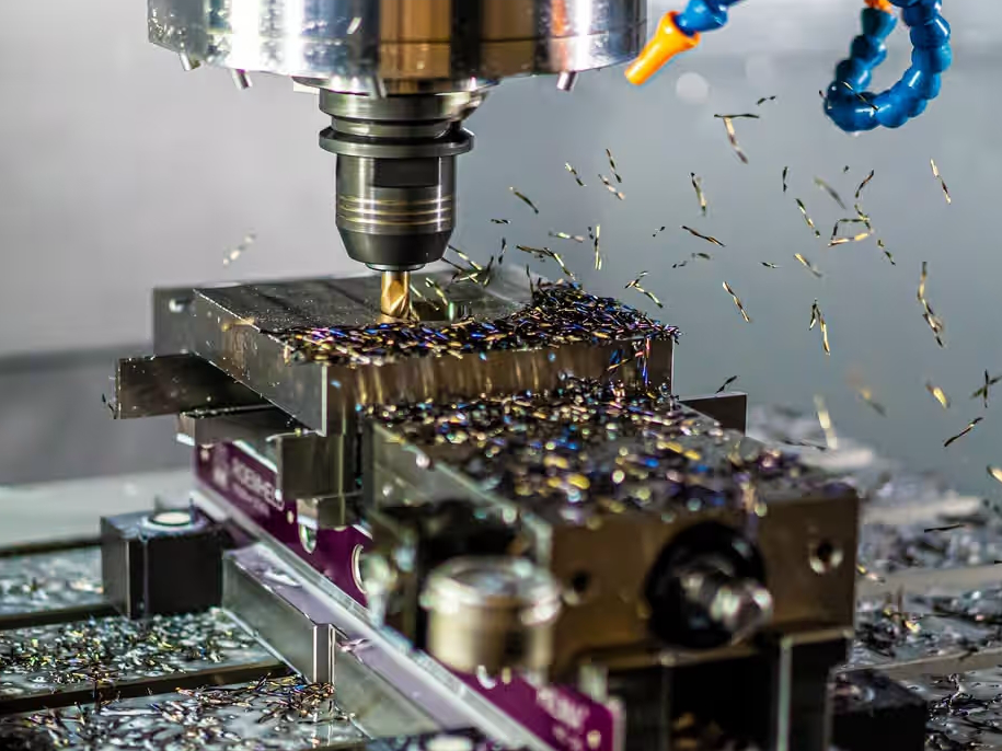
In 3-axis CNC machining, a controller coordinates linear X, Y, and Z motion while the spindle rotates a cutter; ISO 841:2001 names coordinates and motions independently of which component moves physically. CAM converts model and drawing intent into toolpaths. Cutter condition, spindle speed, feed, engagement, overhang, chip control, stock allowance, fixture stiffness, machine condition, and material state govern force, heat, deflection, wear, and the generated surface.
How the Three Axes Work
X axis: provides one linear direction; the machine configuration determines which component moves.
Y axis: provides the perpendicular linear direction used with X for planar and circular paths.
Z axis: provides the third direction for approach, clearance, feature depth, and axial engagement.
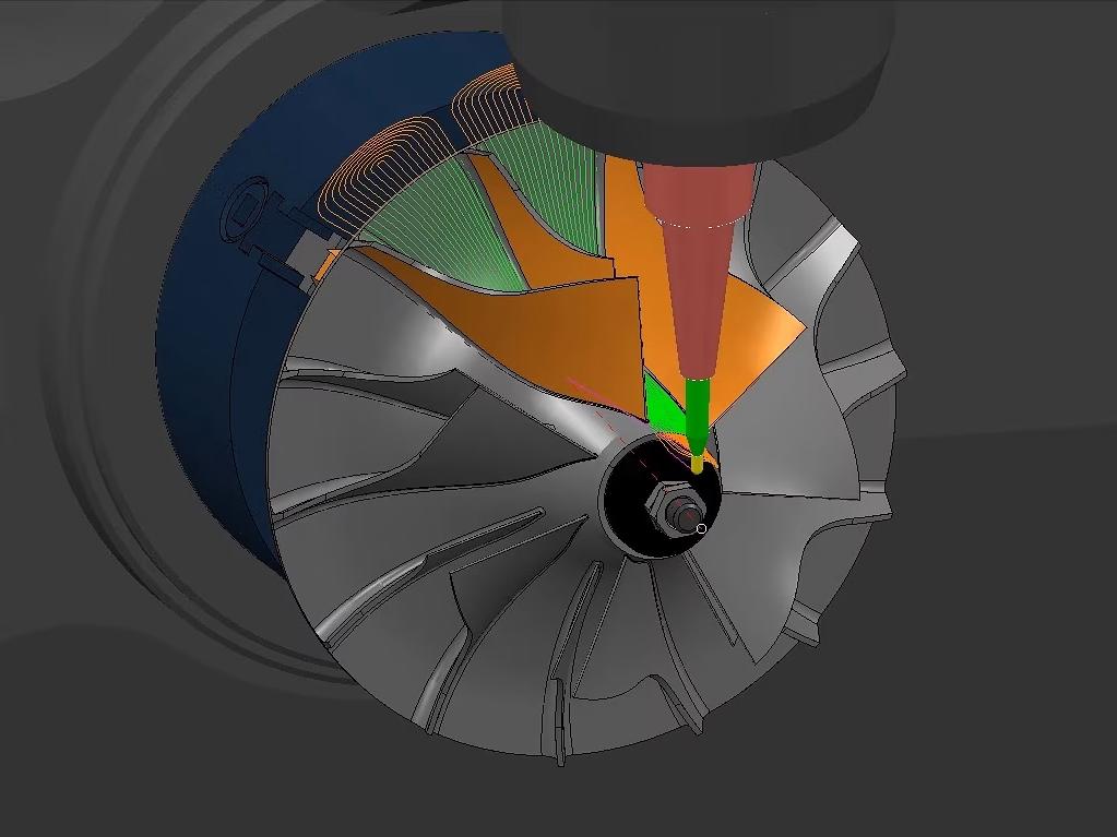
A verified controller and machine configuration may coordinate X, Y, and Z during sloped or contoured cuts, while cutter orientation remains fixed for the scoped operation. The cutter body, holder, and spindle nose all need clearance. Hidden faces, reverse undercuts, and compound-angle holes therefore need re-clamping or another route. Each reorientation adds locating and clamping variables plus a transfer between the machine work coordinate and the drawing datum system.
Typical 3-Axis Milling Workflow
Review the design: Reconcile the controlled model and drawing; identify grade and condition, stock, units, the datum system, critical features, texture, edges, finish, quantity, and required records.
Plan the setup: Map features to cutter approaches, orientations, locators, clamps, and datum transfers. Support cutting loads without blocking access or distorting the part.
Program the toolpaths: Choose roughing and finishing paths for the actual material, tool, engagement, overhang, chip space, and fixture. Simulation checks programmed collisions, not real clamping or stock.
Cut the part: Establish the work coordinate from the planned locators, control heat and chips, retain planned finishing stock where needed, and monitor wear, built-up edge, chatter, and movement.
Deburr and finish: Protect specified edges, seals, threads, and datum features; clean the part and control heat treatment, masking, and coating buildup.
Inspect and report: Check specified characteristics in the required state and datum alignment. Name required material, first-article, in-process, final, and finish records separately.
What Can a 3-Axis CNC Mill Make?
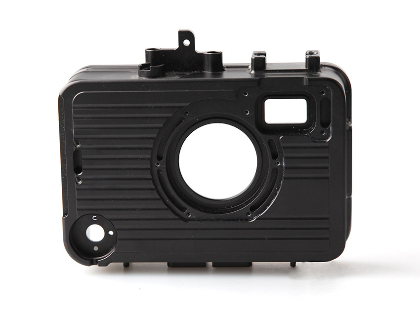
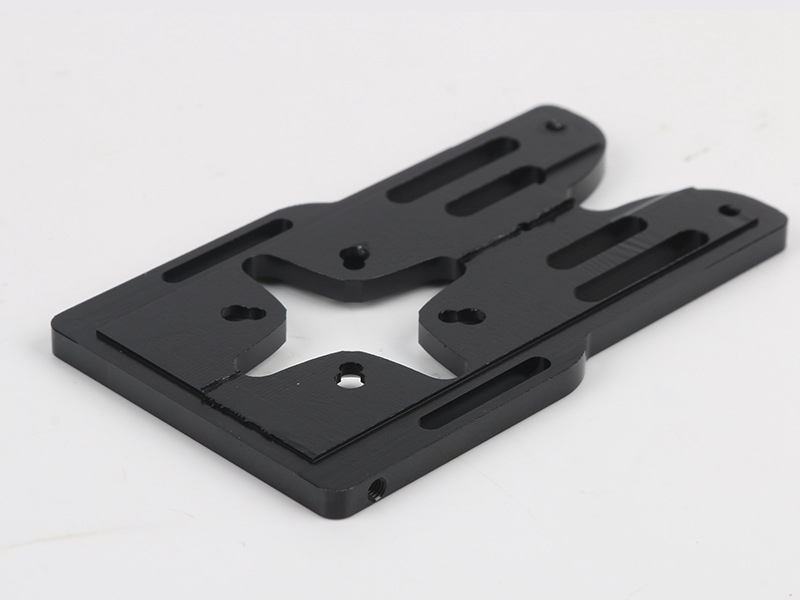
A 3-axis mill can make plates, brackets, housings, fixture bodies, and valve blocks when each critical feature has a collision-free approach from a stable orientation. It also suits CNC machining prototypes under the same conditions. Product labels do not decide suitability; cutter and holder clearance, usable tool length, clamp access, support, setup count, and cross-setup feature relationships do.
Geometries That Work Well
Faces, steps, open pockets, slots, ribs, bosses, and counterbores with cutter, holder, and chip clearance.
Holes and threads aligned with an available setup axis and supported by adequate reach and evacuation.
Contours a fixed-orientation cutter can sweep without a reverse undercut or required tool tilt.
Parts with locating surfaces that support a repeatable setup related to the drawing datum features without unstable contact or clamp distortion.
Repeat lots for which fixture location, offsets, tool response, and inspection can remain controlled.
Important Process Boundaries
A 3-axis route becomes weak when access needs a flexible long-reach cutter, a holder cannot clear a wall, an undercut faces away from every setup, or unstable re-clamping must relate critical features. Extra reach lowers bending stiffness and raises deflection and chatter risk. Review a changed opening, split construction, angled tooling, rotary machining, EDM, broaching, or grinding against the exact feature and acceptance requirement. Record that decision in the quote.
Common Industrial Applications
Across industries, geometry and acceptance conditions matter more than sector labels. Consider a hypothetical engineering scenario: an aluminum valve plate in its specified temper has a cavity on one face, ports on the other, and a sealing face related to hole locations. Ports require a second setup; stock removal may release residual stress, and clamping may bow the plate. A viable plan supports defined contacts, separates roughing from critical finishing, transfers location through durable datum features, and checks sealing geometry and port position after unclamping and finish. The buyer accepts 3-axis only if setup and inspection control those relationships; otherwise the fixture, route, or design changes.
3-Axis vs 4-Axis vs 5-Axis CNC Milling
Three-, four-, and five-axis labels describe controlled motion, not quality grades. Select the least complex route that provides cutter access while preserving datum relationships and inspection. A rotary-axis route may reduce some transfers, but its quote must address programmed mode, rotary workholding, kinematic verification, collision control, and inspection. No route proves conformity without part-specific evidence.
Machine type | How it moves | Best fit | Typical trade-off |
|---|---|---|---|
3-axis | Linear X, Y, Z; fixed cutter orientation | Accessible prismatic features and fixed-orientation contours | Other faces need reorientation and datum transfer |
4-axis | Three linear axes plus one rotary axis | Indexed sides or features around a centerline | May reduce flips; confirm whether the quoted operation is indexed or simultaneous |
5-axis | Three linear plus two rotary or tilting axes | Compound orientations and holder-clearance problems | Quoted route must address rotary kinematics, collisions, workholding, and verification |
Process-route decision: choose 3-axis when stable orientations reach critical features and locating can preserve relationships to the drawing datum system without unacceptable deformation or uncertainty. Review another route when compound angles, holder interference, excessive overhang, or repeated transfers govern the job. Compare setup count, fixtures, programming proof, cutting and tools, inspection, and finish handoff; hourly rate and axis count omit acceptance risk.
Materials for 3-Axis CNC Milling
Material suitability for 3-axis milling is grade- and condition-specific; a family name cannot define the route. Exact grade, temper or heat-treatment condition, stock form, hardness, and directional or filled structure affect force, heat, chips or dust, burrs, tool wear, clamping, and movement after stock removal. Select for function, then review that condition against geometry, finish, and inspection.
Material family | Why it is selected | Design and machining notes |
|---|---|---|
Grade and temper address stated mass, thermal, corrosion, strength, or supply needs | Confirm stock form; control clamping and removal because thin or stressed sections can move | |
Grade and condition match the stated corrosion, strength, temperature, and cleaning environment | Control condition-specific work hardening, heat, chips, and burrs; specify passivation separately | |
Carbon and alloy steels | Grade, hardness, and treatment support the required strength, wear, or structure | State machining and treatment sequence, final condition, stock form, and protection |
Brass and copper | Alloy and temper address conductivity, corrosion, appearance, or mechanical duty | Control heat, chips, smearing, and burrs; protect soft functional surfaces |
Titanium and nickel superalloys | Grade and condition meet defined strength, temperature, mass, or chemical service | Depending on grade and condition, loads, localized heat, work hardening, and wear can govern engagement, rigidity, cooling, and stock |
Engineering plastics | Grade and formulation address the stated functional and regulatory requirements | For each specified PEEK, acetal, nylon, ABS, or filled grade, state formulation, conditioning, stock form, support plan, and inspection state; do not transfer one formulation's plan to another |
Inconel and Monel identify groups, not interchangeable cutting plans. Alloy 718 producer data distinguish mill-annealed or stress-relieved fabrication condition from later age hardening; do not transfer that scope to another nickel alloy. Fired and green ceramic, filled polymer, and laminate states also need separate reviews. Name grade, condition, stock, traceability, and permitted substitutions in the request for quotation (RFQ).
Tolerances, Accuracy, and Surface Finish
Finished-part acceptance separately defines size, geometrical tolerancing, datums, surface texture, and the measurement decision; "high precision" defines none. ISO 230-2:2014 tests individual machine-axis positioning and repeatability under stated conditions. It excludes cutting, fixturing, datum transfer, material and thermal movement, and part-inspection uncertainty, so it is not a finished-part tolerance guarantee.
Practical Tolerance Planning
Plan each tolerance from function and verification. ISO 14405-1:2025 addresses linear size, ISO 1101:2017 geometric specifications, ISO 5459:2024 datums, and the published ISO 21920:2021 series, which ISO marks for revision, addresses profile surface texture; none implies another. Put values, units, datum references, material condition, and process state on the drawing. Where ISO 14253-1:2017 applies, use its conformity decision rule and account for relevant measurement uncertainty near the limits; otherwise state the contractual rule.
Requirement | What to specify | How it is verified |
|---|---|---|
Size | Feature, nominal value, tolerance, units, and acceptance state | Method suited to range and geometry, controlled calibration, and uncertainty fit for the decision rule |
Location | Characteristic, tolerance zone, datum system, modifiers, and revision | Qualified coordinate or functional method with specified alignment |
Flatness and parallelism | Flatness without a datum; parallelism with its datum | Adequate sampling and the required geometric result |
Surface texture | Parameter, limit, surface, direction, and specification conditions | Suitable profile method and settings after the stated process |
Material condition | Grade, treatment, hardness, stock form, and traceability | Approved records and specified tests linked to the lot |
Surface texture, appearance, waviness, burrs, and geometry are different acceptance questions. Cutter condition, runout, engagement, step-over, chatter, built-up material, and later blasting, polishing, or coating change the surface. Specify the functional face, parameter, evaluation conditions, process state, appearance reference, and method. A measurement result supports only the stated characteristic and process state; conformity still follows the agreed decision rule and relevant uncertainty.
Design for 3-Axis Machining (DFM)
Design for manufacture (DFM) aligns access, cutter stiffness, chips, support, datum transfer, deburring, and inspection with function. No pocket ratio, wall thickness, or corner radius is universal. Review material condition, unsupported span, required geometry and surface, approach, and measurement of the released part.
Tool Access and Internal Corners
Check flute length, shank, holder, spindle nose, entry path, and chip flow. A round end mill leaves an internal radius; a design radius larger than the selected cutter radius may reduce corner engagement and allow a stiffer tool when wall and mating requirements permit. If mating function needs a sharp corner, specify a relief or review broaching, EDM, or split construction. Use CAM for collision review, then inspect the actual corner, wall, and mating clearance.
Pocket Depth, Wall Thickness, and Ribs
Deep narrow pockets often require more overhang and restrict chip evacuation. Cutting force can then bend the tool, causing taper or location error; changing force and stiffness can excite chatter, mark surfaces, and wear edges. Improve access, stiffness, engagement, support, chip removal, stock allowance, and grade-specific finishing. Thin walls may deflect under cutting or clamps, spring back after release, then move as heat or residual stock stress redistributes. Balanced roughing, supported low-force clamping, staged release, thermal control, and delayed finishing are conditional controls. Detect problems from sound, tool and surface patterns, then measure geometry after release in the specified state.
Holes, Threads, and Edge Breaks
Define hole diameter, depth, bottom, axis, fit, and state; accept drilling, reaming, boring, or interpolation only if resulting geometry meets the drawing.
Specify thread system, size, class, engagement, incomplete thread, insert option, coating state, and applicable gauge.
Identify sharp, chamfered, radiused, and burr-free edges. Avoid a fixed break unless function supports it; deburring can alter seals and hole mouths.
Review cross-holes for wander, breakout burrs, and trapped chips; provide deburring access and optical or borescope checks where needed.
Mark functional and cosmetic faces, contact zones, and references so clamping, chips, handling, and deburring do not create damage.
Datums and Setups
Define the drawing datum system from functional interfaces, realize it in inspection, and preserve the related datum features through machining. Locators must constrain without conflicting contacts, unstable support, or clamp distortion; no rule says to choose three surfaces. Retain accessible datum features, deliberate locating stock, or qualified soft jaws for later orientations. Probing cannot remove fixture, surface, or datum-simulation uncertainty. Verify critical relationships after transfers and after any unclamping, deburring, treatment, or coating that changes the accepted state.
Surface Finishes and Post-Processing
Plan finishing with machining because removal, buildup, heat, media, masking, and handling can change boundaries, texture, edges, color, and geometry. Specify substrate condition, finish system, target surfaces, masking, tests, and whether dimensions apply before or after treatment. The supplier should name special-process ownership, protect traceability in transfer, review processor records, deburr and clean at the agreed stage, and inspect the final state before delivery.
Finish | Useful for | Important callouts |
|---|---|---|
As-machined | Generated machining surface with no added finish | Relevant texture or appearance, burrs, edges, cleaning, protection, and inspection state |
Aluminum with a defined decorative or protective process scope | Alloy, specification, type, appearance, thickness, sealing, masking, dimensions, and tests | |
Bead blasting or polishing | Visual or preparation result on identified faces | Method, direction, protected edges and datum features, reference sample, cleaning, and inspection |
Specified paint system, color, appearance, and service | Preparation, system, color, thickness, cure, masking, edges, fits, and tests | |
Deposit selected for stated wear, electrical, joining, appearance, or corrosion duty | System, preparation, thickness method, masking, fits, and applicable hydrogen relief | |
Heat treatment | Specified final hardness, strength, or stress state | Grade, incoming and final condition, sequence, hardness, distortion, and final geometry |
What Drives 3-Axis CNC Machining Cost?
3-axis CNC milling cost follows the complete route: stock, programming, setups, fixtures, removal, cutter reach and wear, deburring, finishing, inspection, records, quantity, packaging, and delivery terms. For mass production, fixture effort may be spread across more accepted parts, but repeat work needs tool-life, measurement, change, and capacity controls. Datum transfers, fragile workholding, hidden burrs, special processing, or extensive verification can outweigh short cutting time.
Ways to Reduce Cost Without Losing Quality
Specify obtainable stock and exact condition; require written approval for substitutes.
Apply demanding size, geometry, and texture only where function needs them, while keeping every acceptance rule explicit.
Open access, allow functional radii, and align features to avoid needless long tools, holders, and transfers.
Define edge, burr, masking, and cosmetic requirements by face to prevent avoidable manual work.
Provide first and repeat quantities on one revision; distinguish initial from lot inspection records.
Compare another route when it removes setups, flexible tooling, or difficult inspection; price accepted parts, not machine hours.
Specification-and-quote decision: compare offers only on the same revision, material condition, quantity, finish, critical features, datums, inspection, packaging, destination, and delivery basis. Separate recurring price from programming, fixtures, gauges, and qualification; list exclusions and alternatives. A lower price based on omitted inspection, another finish state, or an unstated tolerance is not comparable.
Quality Control for 3-Axis Machined Parts
Quality control links each requirement to process state, datum alignment, method, sampling, reporting, and conformity decision. A precision machining supplier should map characteristics to methods, not merely list a coordinate measuring machine (CMM). ISO 10360-2:2009 acceptance or reverification of a CMM, measurement system analysis (MSA), first-article inspection, and a study under an applicable ISO 22514 process-capability scope answer different questions; none substitutes for feature-specific conformity. Calibration, range, fixturing, access, software, environment, operator method, and uncertainty affect the evidence, while CMM resolution does not establish part tolerance.
Match inspection to failure: view burr-prone intersections; examine chatter marks; measure thin walls and datum relationships after unclamping; and verify treated or coated features in final state. In-process checks reveal wear, offset drift, or movement; final inspection supports lot acceptance. Confirm revision, nonconformity, traceability, tool-change, record, and deviation controls.
How to Choose a 3-Axis CNC Milling Service
Choose a 3-axis CNC milling service from evidence for the proposed part, route, and acceptance plan, not axis count or equipment names. Require written assumptions, inaccessible features, setups, datum strategy, risk controls, special-process ownership, inspection, records, and schedule basis. Evaluate:
Machine and workholding capability: Proposed setups, usable envelope, tool access, fixture contacts, clamp zones, datum transfer, and relevant verification.
Programming and engineering support: Controlled CAM inputs, collision and stock review, marked-up ambiguities, and approval before design assumptions change.
Material and finishing network: Exact condition, traceability, substitutions, process ownership, transfer records, and processor acceptance evidence.
Quality process: Characteristic-method plan, calibration, uncertainty, datum alignment, report, nonconformity, and first-article versus capability evidence.
Capacity and delivery: Schedule basis across stock, fixtures, tools, machining, outside processing, inspection, transport, and repeat-route changes.
Communication: Accountable technical contact and written assumptions, questions, deviations, handoffs, approvals, revisions, and release status.
ISO 9001:2015 certification, if required and verified for the organization, site, and scope, addresses a management system; it does not prove a machine, delivery date, or part. Pair it with route and part records. Close geometry, material, finish, inspection, documentation, and delivery exceptions before ordering, with deviations tied to the revision.
What to Send for a CNC Milling Quote
A useful 3-axis CNC milling RFQ must give each supplier the same revision-controlled technical and commercial basis. Include enough information to decide cutter access, setup orientations, datum transfer, material response, post-processing, inspection, and delivery without inventing requirements. At minimum, provide:
Solid model plus controlled 2D drawing; state which governs if geometry, dimensions, geometric dimensioning and tolerancing (GD&T), or notes conflict.
Exact grade, condition, stock constraints, traceability, prohibited substances, and substitution approval.
Prototype, first-order, lot, and repeat quantities; separate one-time fixtures or gauges and route-retention needs.
Units, datum features and reference framework, critical size and geometry, fits, texture, edges, cosmetic faces, mates, and setup-driving orientations.
Treatment and finish specification, sequence, appearance, masking, allowance, threaded fits, and dimensional acceptance state.
In-process, first-article, final, or capability evidence; characteristics, sampling or study basis, report, decision rule, packaging, destination, and delivery basis.
Part number, revision, date, change summary, terms, deviations, and authorized technical and release contacts.
Require proposed orientations, datum transfers, access risks, long tools, deburring, process handoffs, inspection, exclusions, and alternatives. Resolve discrepancies before comparing price or schedule; an unpriced assumption can return as redesign, deviation, rework, or rejection.
Conclusion
Choose 3-axis when stable orientations provide access and the workholding, datum, material, thermal, deburring, finish, and inspection plans preserve functional relationships. It is a process route, not a quality label; acceptance belongs to specified characteristics and the agreed measurement decision.
If undercuts, compound angles, overhang, or re-clamping govern risk, compare alternate routes on accepted-part cost. Otherwise, issue the complete RFQ and require the CNC machining partner to return setup, datum, exception, finish, inspection, and delivery assumptions. Select the documented route that matches the revision, not an unsupported precision claim.
FAQs: