How to Choose Between 3-Axis, 4-Axis, and 5-Axis CNC Milling for Custom Parts
Choosing between CNC milling platforms is not simply a matter of selecting more axes for better performance. For custom parts, the correct decision depends on how geometry, tolerance, surface finish, machining time, fixture access, and order volume interact in real production. A simple bracket may be produced efficiently on a 3-axis machine, while a cylindrical part with radial features may benefit from 4-axis indexing, and a highly contoured aerospace or medical component may require true 5-axis interpolation to reach critical surfaces in one setup. Selecting the wrong platform can increase cost, lead time, fixture complexity, and dimensional risk even if the part is technically machinable.
For buyers and product engineers, the most effective way to choose is to evaluate axis capability against part function. Questions such as how many faces need machining, whether undercuts or angled surfaces are required, how many times the part must be re-clamped, and which tolerances are relationship-critical usually determine the right route. In practice, the decision is tied closely to multi-axis machining, the expected production workflow, and the balance between machining precision and commercial efficiency. A good selection process reduces setup count, improves consistency, and prevents paying 5-axis rates for geometry that a simpler process can already control well.
What 3-Axis, 4-Axis, and 5-Axis CNC Milling Actually Mean
The axis count describes how the cutting tool and the part move relative to each other during machining. In a 3-axis milling system, the tool moves linearly in X, Y, and Z directions. This is the most common configuration for prismatic parts, planar surfaces, slots, pockets, and drilled features accessed from one main direction. In 4-axis milling, a rotary axis is added, usually allowing the part to rotate around one axis so multiple sides can be machined with fewer refixturing steps. In 5-axis milling, two rotary motions are introduced, allowing the tool or part to approach surfaces from many angles and machine complex geometry with significantly better accessibility.
Although the definition sounds simple, the production impact is substantial. Every additional axis can reduce manual repositioning, shorten setup chains, and improve geometric continuity between features on different faces. However, additional axes also increase programming complexity, machine hourly rate, fixture strategy requirements, and process planning demands. This is why axis selection should be driven by feature logic rather than marketing language. The basic capability differences are also connected to 3 Axis CNC Milling, 4 Axis CNC Milling, and 5 Axis CNC Milling.
Core Decision Rule: Match Axis Count to Part Geometry
The fastest way to select the correct milling route is to classify the part by geometry rather than industry name. If the part is largely flat-sided, with most features reachable from the top and possibly one or two secondary orientations, 3-axis milling is usually the most economical solution. If the part is cylindrical or needs indexed machining around its perimeter, 4-axis machining often reduces multiple setups and improves feature position consistency. If the part contains compound angles, sculpted surfaces, deep cavities, impellers, blisks, turbine-like forms, organic medical geometry, or features that must remain highly accurate relative to each other across many faces, 5-axis becomes the preferred route.
This geometry-first logic matters because complexity does not always mean freeform shape. Many custom industrial parts are complex because of many holes, slots, and datum relationships, but they still do not require simultaneous 5-axis movement. Conversely, a part with relatively few features may still require 5-axis if the tool must maintain optimal contact angle on contoured surfaces or avoid long, unstable tool reach. The goal is not to choose the most advanced process, but the one that creates the required geometry with the lowest combined cost of setup, cycle time, scrap risk, and inspection burden.
When 3-Axis CNC Milling Is the Best Choice
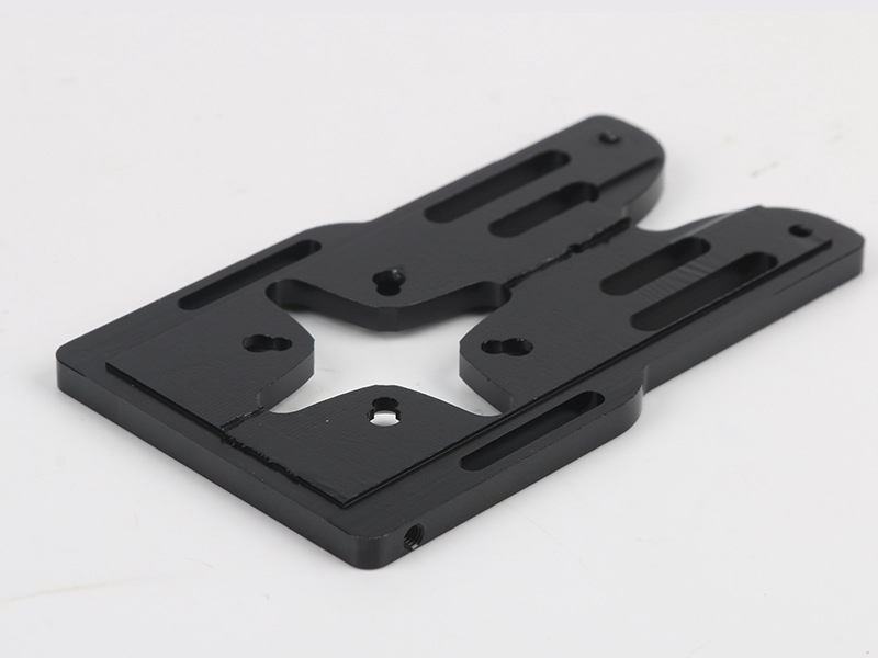
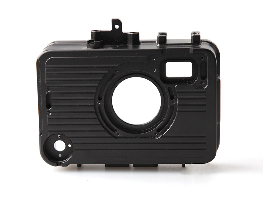
3-axis milling remains the most cost-effective platform for a wide range of custom parts. It is ideal for flat plates, housings, mounting blocks, brackets, adapter plates, covers, manifolds with accessible features, and many prototype components with predominantly vertical walls and horizontal features. Because the machine structure, programming workflow, and fixturing approach are comparatively straightforward, 3-axis machining usually offers lower hourly rates and faster programming turnaround than more advanced multi-axis routes. For many buyers, especially in early product development, that makes it the default starting point.
From an engineering standpoint, 3-axis is strongest when tool access is simple and the part can tolerate multiple setups without degrading critical relationships. Typical tolerances can be controlled very well when datums are clear and fixture repeatability is stable. Many aluminum, steel, brass, and engineering plastic components are efficiently produced this way, especially in prototype or low-to-medium complexity runs. It is also often the right route when parts require secondary operations such as tapping, deburring, or surface finishing but do not need advanced angular toolpaths. Material choice further affects performance, as discussed in best materials for CNC milling.
Common Custom Parts Suited to 3-Axis Milling
Part Type | Why 3-Axis Works Well | Typical Design Condition | Commercial Advantage |
|---|---|---|---|
Mounting brackets | Mostly planar faces, slots, and holes | Features accessible from one or two directions | Low programming cost and fast setup |
Electronics housings | Pockets, bosses, and side features are manageable | Rectangular geometry with simple fixturing | Efficient for prototype and pilot builds |
Fixture plates | Flatness and hole position are primary concerns | Datum-driven, prismatic geometry | High value with stable dimensional control |
Cover plates | Simple contouring and drilling operations | Low wall angle complexity | Short machining cycle time |
Plastic prototypes | Easy access and lower cutting loads | Moderate tolerance and cosmetic needs | Economical for rapid iteration |
When 4-Axis CNC Milling Creates Better Value
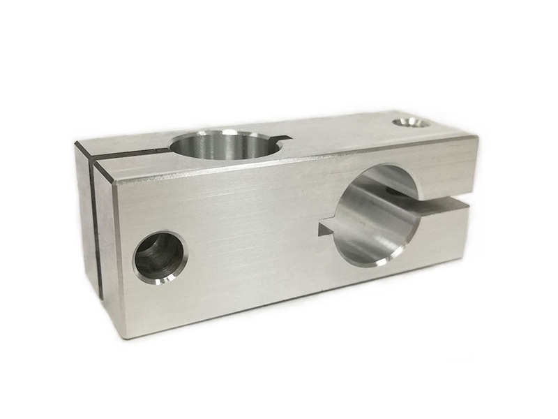
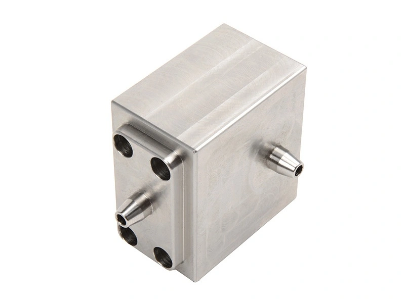
4-axis CNC milling becomes attractive when a part needs machining on several sides around a rotational centerline or when indexing can eliminate repeated manual re-clamping. Typical candidates include shafts with milled flats, valve bodies, cylindrical housings with side ports, gear-related components, and parts requiring features distributed around the circumference. The extra rotary axis can greatly improve positional consistency between side features because the machine handles the angular orientation instead of relying on multiple manual setups.
For many custom parts, 4-axis is the practical middle ground between simple 3-axis production and high-cost 5-axis machining. It reduces labor time, shortens cumulative setup error, and often improves productivity in medium-volume work. This is especially useful when the part must be machined on four sides or when indexed rotation allows the same datum structure to stay active throughout most of the cycle. In many cases, 4-axis provides enough access improvement to avoid the full programming and machine cost associated with simultaneous 5-axis motion.
Typical 4-Axis Use Cases for Custom Parts
Part Geometry | 4-Axis Benefit | Why 3-Axis Is Less Efficient | Why 5-Axis May Be Unnecessary |
|---|---|---|---|
Cylindrical body with radial holes | Indexed rotation improves angular positioning | Requires repeated manual reorientation | No complex compound surfacing required |
Shaft with flats and slots | Multiple faces machined in one holding | More fixture changes and alignment work | Tool approach remains relatively simple |
Valve manifold with side ports | Better access to several side features | Stacked setups raise tolerance risk | No need for continuous dual-axis articulation |
Rotational industrial hardware | Improves productivity in repeated indexing | Operator-dependent repositioning adds time | Feature set is indexed rather than sculpted |
When 5-Axis CNC Milling Is Worth the Investment
5-axis milling is usually justified when part geometry, tolerance relationships, or surface quality requirements make fewer setups strategically more valuable than lower machine cost. It is the preferred solution for freeform surfaces, impellers, turbine blades, medical implants, aerospace structural parts with angled pockets, and precision components requiring multiple compound-angle features. Because the tool can approach the workpiece from many orientations, 5-axis machining can reduce tool overhang, improve surface finish, maintain better cutting conditions, and preserve dimensional relationships that would otherwise be degraded by repeated clamping.
This does not mean 5-axis is always the most expensive route overall. For certain parts, the reduced setup count can offset the higher machine rate. A component that would require five fixtures, three inspection transitions, and long-reach tools on a 3-axis platform may be faster, more accurate, and even lower risk on a 5-axis machine. In addition, simultaneous 5-axis toolpaths often improve contact conditions on contoured surfaces, which helps surface finish and reduces scallop inconsistency. For parts in sectors such as Aerospace and Aviation or Medical Device, these advantages are often decisive.
Engineering Reasons to Move Up to 5-Axis
The most important technical reason to use 5-axis is not merely access, but control. When the tool can remain normal or near-optimal to the machined surface, cutting forces are better distributed and local finish quality improves. Tool stick-out can often be shortened, which reduces deflection and vibration. Deep cavities become more practical because the tool can tilt rather than extend excessively. Feature relationships across multiple faces are also preserved more reliably because the part can remain in one clamping condition while many surfaces are machined.
These advantages become especially visible in hard-to-machine materials and high-value parts. Titanium and superalloy components, for example, are sensitive to heat, tool wear, and tool deflection. If a 5-axis strategy improves access and shortens tool length, it may directly improve dimensional stability and reduce cutting load concentration. This is one reason why 5-axis logic is frequently paired with demanding materials such as Titanium and Superalloy.
How Axis Count Affects Tolerance Control
Tolerance capability is influenced by more than the machine specification. In actual production, one of the largest causes of dimensional inconsistency is setup transfer. Every time a custom part is removed and re-clamped, there is a risk of introducing angular deviation, datum shift, stack-up error, or surface damage. This means that moving from 3-axis to 4-axis or 5-axis can improve tolerance control not only because the machine is more advanced, but because the process chain becomes shorter and more stable.
However, simpler machines can still hold excellent tolerances when the geometry is setup-friendly. For a prismatic part with well-defined datums, 3-axis machining may achieve all required dimensions efficiently. The right question is therefore not “Which machine is most accurate?” but “Which process creates the least geometric risk for this specific part?” A structured tolerance review should consider datum hierarchy, number of setups, critical relative angles, hole-to-surface relationships, and local finish needs. This decision process is closely related to understanding machining tolerances and tolerance-function-cost balance.
Surface Finish Comparison Between 3-Axis, 4-Axis, and 5-Axis
Surface finish quality depends on tooling, cutting parameters, machine stability, material behavior, and access angle. On flat or simple contoured surfaces, 3-axis milling can already achieve excellent results. But when the part includes organic surfaces, compound curves, or narrow deep areas, 5-axis machining often generates better finish because the tool can maintain a more favorable contact angle. This reduces scallop irregularity, helps chip evacuation, and allows shorter, more rigid tools to be used.
4-axis machining can also improve finish by reducing repositioning and preserving smoother feature continuity around rotational parts. In all cases, finishing requirements should be evaluated before process selection because cosmetic surfaces, sealing faces, optical-adjacent parts, and aerodynamic profiles each impose different constraints. Secondary finishing may still be required depending on the material and application. Finish planning is therefore tied to both the base milling route and any post-process strategy, as explained in CNC machined parts surface finishes.
Cost Comparison: What You Actually Pay For
The cost difference between 3-axis, 4-axis, and 5-axis machining is not only about hourly machine rate. Buyers are effectively paying for a full production system that includes programming time, fixturing complexity, machine cycle time, operator intervention, inspection difficulty, and scrap risk. A 3-axis part may have a low nominal machining rate but become expensive if it needs four setups, custom fixtures, and secondary blending to correct mismatch between faces. A 5-axis part may appear expensive at first glance but become efficient when it eliminates multiple fixtures and preserves first-pass yield.
For this reason, cost should be reviewed at the job level rather than the machine level. Complex parts often behave nonlinearly: a small increase in geometry complexity can sharply increase 3-axis production cost, while the same change may have only moderate effect in a 5-axis workflow. Material also matters. Aluminum generally machines quickly and may tolerate simpler strategies, while titanium and superalloys often benefit more from advanced access control. The commercial side of this decision connects strongly to what determines the cost of CNC milled parts and ways to reduce CNC machining costs.
Practical Cost Logic by Axis Option
Axis Option | Usually Lowest Cost For | Main Cost Driver | Common Hidden Cost Risk |
|---|---|---|---|
3-Axis | Simple prismatic parts and quick prototypes | Multiple setups and manual repositioning | Datum transfer error and added labor |
4-Axis | Indexed multi-side and cylindrical parts | Rotary setup and moderate programming effort | Overuse on parts that do not need rotation |
5-Axis | Complex geometry and high-value precision parts | Programming, machine time, process planning | Using 5-axis for simple geometry without ROI |
How Production Volume Changes the Best Choice
Axis selection should not be made without considering production quantity. In low-volume prototyping, 3-axis machining may remain attractive because the programming and fixture burden of advanced platforms may not be justified if the geometry is manageable. In contrast, for recurring production runs, the value of reduced setup time and better repeatability becomes much more significant. A 4-axis or 5-axis route that saves 8 to 15 minutes per part can create substantial cost reduction over hundreds or thousands of units.
Volume also affects tolerance economics. In small quantities, manual intervention may be acceptable. In larger batches, repeatability becomes more valuable than isolated cycle speed because variation compounds across the lot. That is why advanced axis strategies are often paired with Low Volume Manufacturing for product launch phases and later expanded into Mass Production when the geometry and quality logic are fully validated.
Material Selection Can Change the Axis Decision
The same geometry may justify different axis routes depending on the material. Aluminum parts often tolerate more aggressive metal removal and longer tool reach, making 3-axis or indexed 4-axis strategies viable for many designs. Stainless steel, titanium, and nickel-based alloys behave differently. They generate more heat, impose higher cutting forces, and are less forgiving of chatter or deflection. Under those conditions, tool approach angle and stick-out become more important, and a 5-axis strategy may produce better dimensional control and tool life even if the part geometry alone does not obviously require it.
This is especially important in parts that combine deep pockets, thin walls, and tight tolerance relationships. In softer materials, the part may still machine well with conventional setups. In titanium or superalloy, the same setup could become unstable. Buyers comparing quotes should therefore avoid evaluating axis choice without also reviewing the work material and critical feature layout. Material guidance can start from service families such as Aluminum, Stainless Steel, and Plastic.
Design for Manufacturability Rules That Help Axis Selection
Many axis-selection problems begin as design problems. If engineers define unnecessary compound angles, inaccessible deep corners, overly tall wall sections, or excessive undercuts, they can unintentionally force a 5-axis process where 3-axis would otherwise work. Good DFM practice therefore starts by asking whether critical surfaces truly need to be placed on different angular planes, whether internal radii can be increased, whether feature depth-to-width ratio can be reduced, and whether parts can be split or reoriented to simplify machining access.
At the quoting stage, this kind of review can substantially reduce part cost. A supplier may recommend slight changes to wall transitions, corner radii, datum locations, or feature direction so the part can move from a complex simultaneous strategy to a simpler indexed or 3-axis route. In custom part programs, these small adjustments often create large savings without changing product function. This planning logic is aligned with DFM for CNC machining.
Industry Examples Where Each Axis Option Makes Sense
Industry | Typical Axis Choice | Representative Part Logic | Why It Fits |
|---|---|---|---|
3-Axis or 4-Axis | Brackets, mounts, housings, indexed hardware | Mostly prismatic features with moderate complexity | |
4-Axis or 5-Axis | Lightweight structural parts and actuator interfaces | Multiple faces and angle-sensitive geometry | |
3-Axis to 5-Axis | Prototype brackets to complex performance components | Wide range of geometry and batch needs | |
3-Axis or 4-Axis | Valve bodies, fixtures, machine details | High value in efficient multi-side machining | |
5-Axis | Contoured structural or turbine-adjacent components | Complex surfaces, strict tolerance, expensive materials |
How Neway Selects the Right CNC Milling Route for Custom Parts
At Neway, axis selection is treated as part of the engineering review rather than a fixed sales category. The decision starts from part geometry, material, critical tolerance zones, surface requirements, and target order quantity. Engineers assess whether the component is best handled by standard prismatic milling, indexed rotary machining, or simultaneous multi-axis toolpaths. This prevents both under-specifying the process and overengineering it. In many projects, the best commercial result comes from hybrid planning, where roughing, indexing, finishing, and secondary processes are combined strategically to control both cost and quality.
This route-selection logic is also integrated with broader manufacturing support, including CNC Machining Prototyping, Precision Machining, and One Stop Service. For buyers, that means the recommendation is based on how the part should actually be manufactured and inspected, not simply which machine sounds most advanced.
Conclusion: How to Make the Right Axis Choice
The right choice between 3-axis, 4-axis, and 5-axis CNC milling depends on the relationship between geometry, access, tolerance, surface finish, material behavior, and volume. Use 3-axis when the part is mainly prismatic and setup transfer does not threaten function. Use 4-axis when indexed rotation can replace repeated re-clamping and improve multi-side efficiency. Use 5-axis when complex surfaces, compound angles, difficult materials, or tight inter-feature relationships make one-setup machining strategically valuable. The smartest selection is the one that produces the required part quality with the lowest total manufacturing risk, not simply the highest machine capability.
FAQ
What is the difference between 3-axis, 4-axis, and 5-axis CNC milling?
When should I choose 5-axis CNC milling instead of 3-axis machining?
Is 4-axis CNC milling more cost-effective for complex parts?
Which part geometries are best suited for multi-axis CNC milling?
How does axis selection affect machining accuracy and lead time?