DFM for CNC Machining: 10 Golden Rules to Optimize Designs and Reduce Costs
Introduction
DFM for CNC machining optimizes designs by matching part geometry, tolerances, materials, finishes, and inspection requirements with a realistic machining plan before quoting or production. The 10 rules below reduce cost when they prevent avoidable setups, special tooling, unstable thin walls, unclear datums, late finishing conflicts, and inspection surprises. They do not work as generic shortcuts. A feature that looks expensive may be necessary for sealing, alignment, fatigue life, or assembly. A feature that looks simple may still create risk if the tool cannot reach it, the part cannot be held, or the requirement cannot be measured. Good DFM asks what the part must do, what surfaces actually control function, and what evidence the buyer needs at acceptance. The review should answer four questions: what must be preserved, what can move, what process creates risk, and what proof will release the part. A DFM comment is useful only when it names the feature, the reason for risk, the proposed change, and the buyer decision needed. Those answers help engineering protect function and help purchasing compare quotes on the same basis. The expected output is a cleaner RFQ and a traceable list of open engineering decisions. Any claimed reduction in setup, rework, or cycle time must be tied to the accepted design change and the quoted process route.
Here are 10 golden DFM rules every engineer should follow when designing CNC-machined parts. Use the rules as a review framework before sending CAD and drawings to a supplier. First, mark the features that control fit, sealing, motion, load transfer, or appearance. Then separate those features from areas that only need practical manufacturability. Finally, ask the supplier to confirm tool access, setup strategy, stock condition, finishing sequence, deburring method, and inspection approach. This keeps the conversation practical. The goal is not to make every part simple. The goal is to make the required complexity visible, controlled, and worth paying for. Apply the rules before final tolerance release, because late DFM changes can affect mating parts, fixtures, finishing masks, and inspection gauges. When a rule conflicts with product function, keep the function and document the reason. When a rule affects only cost or cosmetic preference, decide whether the saving is worth a drawing revision.
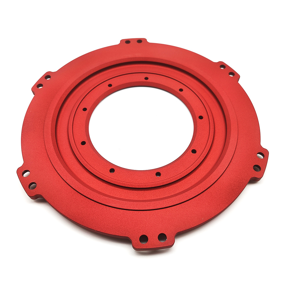
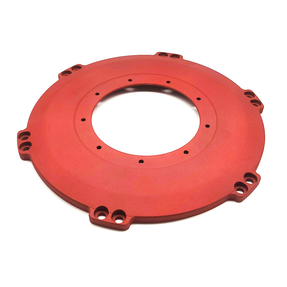
1. Avoid Unnecessary Tight Tolerances
Tight tolerances should be assigned only to features that control function, assembly, sealing, motion, or inspection datums. A tolerance that looks precise on a drawing can add slower finishing cuts, more stable fixturing, extra inspection time, and higher scrap risk. That cost is justified for a bearing bore, a sealing groove, a datum slot, or a close-fit assembly face. It is usually not justified for a hidden pocket wall or a cosmetic surface with no mating part. DFM should classify each dimension as functional, assembly-related, cosmetic, or process-control information. Inspection is part of that decision. If a tolerance cannot be checked with the agreed datum scheme, measuring equipment, or gauge method, the supplier and buyer may still disagree after machining. When a drawing invokes ASME Y14.5, datum references and position, profile, flatness, or perpendicularity controls provide a common GD&T language; the standard does not decide which tolerance the product needs. Those controls should express design intent, not hide it. The RFQ needs assembly requirements, mating-part data, gauge needs, and inspection priority. A supplier can then quote the difficult features accurately instead of applying high-cost machining assumptions to the whole part.
2. Design with Standard Tool Sizes
Standard cutter sizes can reduce CNC machining cost when pocket radii, slot widths, bosses, and corner reliefs fit tools from the supplier's normal library. Diameter alone is not enough: flute length, neck clearance, corner geometry, holder envelope, material, feature depth, and surface requirement determine whether the tool can cut rigidly. A small cutter can reach a tight corner, yet a long small cutter may chatter, deflect, or leave visible tool marks. A larger cutter can remove material efficiently, but the design must allow the cutter radius and clearance. Internal corner radii should normally be larger than the cutter radius when finish and cycle time matter. Narrow slots, deep grooves, and awkward radii can force custom tooling or multiple finishing passes. Slots should also be checked for chip evacuation, entry direction, and whether the bottom surface really needs a fine finish. A slot that only clears a cable may allow a larger radius than a slot that guides a sliding component. Ask which tool and holder combination drives the quote, including the feature that sets reach or flute-length demand. If one detail forces special tooling, review its function before freezing the design.
3. Maintain Uniform Wall Thickness
Uniform wall thickness improves machinability because cutting force, heat, and clamping pressure act more predictably on the workpiece. Thin walls can vibrate during roughing, move after unclamping, or distort when a finish cut releases residual stress. Thick-to-thin transitions can also create uneven heat and local stiffness changes. A practical DFM review should check whether the wall supports the load, whether the wall can be reached with a stable cutter, and whether the remaining material can survive deburring and finishing. Consider an aluminum electronics housing with a long thin side wall and a gasket groove near the top edge. If the wall is treated like a normal pocket wall, the groove may shift after unclamping and fail the seal check. A better plan may leave roughing stock, change the cutting order, add a local rib, open a corner radius, or move a cosmetic relief away from the sealing area. If the wall cannot be thickened, the drawing should identify which surface controls function and which surface can accept process variation. Validation should use prototype machining, CMM checks, or assembly fit checks on the features that carry function.
4. Optimize Hole Depth-to-Diameter Ratios
Hole depth-to-diameter ratio affects tool stiffness, chip evacuation, coolant access, straightness, and inspection confidence. A hole becomes a deep-hole review item when its depth relative to diameter makes tool guidance, coolant delivery, chip removal, straightness, or surface finish difficult for the proposed drill family. The screening point depends on diameter, material, tool design, coolant delivery, machine, entry condition, and acceptance requirement. The feature may remain unchanged, but the quote should identify the drilling route, tool type, coolant or chip-control strategy, inspection method, and acceptable alternatives. Blind holes also need bottom clearance, chip room, and clear thread-depth notes. Threaded blind holes need a difference between drilled depth and usable thread depth, or the tap may bottom before the drawing requirement is met. Cross holes and angled holes add burr and breakthrough risks that should be reviewed before machining. If a hole is only for weight reduction or cable access, shortening the depth may reduce cost without hurting function. If the hole controls fluid flow, alignment, or assembly, the RFQ must define diameter, depth, surface finish, positional tolerance, datum reference, and gauge or measurement method. Good DFM turns deep holes into planned features, not late surprises in production.
5. Minimize Undercuts and Internal Sharp Corners
Undercuts and internal sharp corners increase CNC machining cost because ordinary rotating tools cannot create every hidden surface or square internal edge. If an undercut is functional, document the access direction, mating feature, and acceptance requirement. If the undercut is only a legacy shape or cosmetic preference, redesigning the relief may remove a secondary operation. Some internal details require EDM machining, special form tools, broaching, or a split-part design. Those options can be valid, but they should be chosen early because they affect cost, lead time, surface texture, and inspection. Internal corners should use a radius that matches a practical cutter and leaves room for finishing. A sharp corner at the bottom of a deep pocket may create chatter, tool wear, and hand-deburring risk. If a square internal corner is required for a mating insert, DFM should compare EDM, relief notches, and insert redesign before quoting. Review the corner against load, sealing, mating-part clearance, assembly access, and legacy-drawing intent before selecting the machining route. DFM protects the functional corners and removes the expensive ones that do not matter.
6. Reduce Setup Changes
Setup changes affect cost because each reorientation needs fixturing time, datum transfer, program control, and inspection alignment. A design that groups critical features around the same datum scheme is easier to machine and verify. Features placed on many faces can still be manufacturable, but they should be reviewed for access, datum relationship, and tolerance stack-up. Multi-face parts may benefit from multi-axis machining when the geometry, material, and fixture allow stable cutting. Multi-axis machining does not automatically lower cost. It helps when it reduces re-clamping, improves tool angle, protects datums, or reaches angled features without a risky secondary setup. A single setup can still be expensive if the part is hard to clamp or if tool holders collide with tall features. Setup reduction should be judged by total process evidence, not by operation count alone. The review should include fixture contact areas, clamp distortion risk, probe access, and which features are measured in each orientation. Mark the datums that control assembly and the faces that may accept fixture contact without cosmetic or functional damage. The supplier can then decide whether 3-axis, indexed multi-axis, or simultaneous multi-axis machining is the best route for the design.
7. Choose Machinable Materials
Material choice affects DFM because machinability, strength, corrosion resistance, heat resistance, burr behavior, and finishing response do not move together. aluminum 6061 can be a practical choice for brackets, covers, housings, and fixtures when stiffness, thread load, temperature, and corrosion conditions allow it. titanium can be selected for strength-to-weight and corrosion performance, but heat control, tool wear, burrs, and galling risk need attention. Inconel can be justified for high-temperature or severe-corrosion service, yet geometry, tool engagement, and inspection access become more important. The material condition matters as much as the name. Temper, heat treatment, plate or bar form, casting condition, and stress-relief history can change how the part moves during machining. Material substitution should be reviewed against the real service condition. Replacing a difficult alloy with aluminum may reduce machining effort, but the buyer must recheck stiffness, threads, corrosion exposure, coating compatibility, and temperature. Material selection cannot rest on strength or purchase price alone. Freeze the exact grade, condition, governing specification, and stock form, then ask the supplier to compare machining risk, finish route, tolerance sensitivity, supply assumptions, and acceptance evidence.
8. Consolidate Features Where Possible
Feature consolidation can reduce machining time when it removes duplicate pockets, unnecessary bosses, repeated small holes, or decorative details that add tool changes without adding function. Consolidation should not erase features that help assembly, drainage, weight balance, sealing, or inspection. A good DFM review asks why each feature exists and what happens if the feature changes. Adjacent holes may be combined only if the new opening does not weaken the part, confuse assembly, or create a harder deburring problem. A raised pad may be removed only if the mating part still seats correctly. A cosmetic contour may be simplified only if the visible surface still matches the product requirement. A feature that reduces one machining step may add inspection difficulty, finishing damage, or assembly confusion. That tradeoff should be visible before approval. Consolidation also helps suppliers quote consistently because the machining route becomes easier to compare. Mark each feature as mandatory, adjustable within stated limits, or optional before the supplier proposes consolidation. That decision prevents the supplier from guessing whether a boss, groove, rib, or pocket is functional. It also keeps cost reduction tied to design intent rather than random simplification.
9. Plan for Surface Finish Early
Surface finish should be planned before machining because finishing can change dimensions, edge condition, appearance, corrosion behavior, and inspection timing. If anodizing is required, the drawing should state whether functional dimensions apply before anodizing, after anodizing, or after masking. If electropolishing is required, exposed edges, grooves, and thin sections should be reviewed because material may be removed from accessible surfaces. Powder coating, plating, passivation, bead blasting, polishing, and PVD coating also need finish zones and masking decisions. A bore, thread, bearing seat, or sealing face may require protection from coating buildup or finish removal. DFM should connect the finish to machining allowance, deburring sequence, inspection method, and packaging sensitivity. Finish-related dimensions should be labeled with acceptance timing. A note that states a dimension applies after finishing establishes the measurement stage; a general coating note does not. Include the finish specification, appearance class, roughness location, corrosion exposure, masking boundaries, and surfaces that must remain uncoated or unpolished. This avoids a common failure mode: a part passes its pre-finish check but fails after finishing changes a functional dimension.
10. Annotate Drawings Clearly and Completely
Clear drawings reduce CNC machining risk because the 3D model rarely communicates every tolerance, thread, finish, datum, material condition, and inspection requirement. A complete 2D drawing should identify critical-to-function dimensions, datum scheme, GD&T controls if used, thread depth, edge breaks, surface roughness, finish zones, material grade, heat treatment, and revision level. It should also state whether dimensions apply before or after finishing when that affects function. Ambiguous notes create expensive decisions during quoting. A supplier may quote conservative tolerances, choose unnecessary inspection, or miss a feature that should have been protected. The RFQ should include the 3D model, 2D drawing, expected volume, target application, mating parts if available, preferred material, finish requirement, inspection report needs, and any features that cannot be changed. A drawing package is also a decision record. It should show what changed after DFM review and who approved the change before purchasing releases the order. If the supplier proposes a DFM change, the change should be returned as a marked drawing comment or model revision note. That makes approval traceable and keeps the final machining plan aligned with the released drawing.
Conclusion
Applying DFM principles early in the design phase reduces CNC machining costs when the review turns design intent into controlled machining, finishing, and inspection decisions. The strongest DFM review does not simply ask for looser tolerances or simpler geometry. It identifies which features create cost, why they create cost, and whether they protect function. It also shows where a prototype, first-off inspection, material trial, finish sample, or assembly check is needed before production. For the buyer, the next step is to send clean CAD, a controlled drawing, material condition, finish requirements, critical features, and expected order volume to experienced CNC machining suppliers. The supplier's response should separate mandatory design requirements from optional cost reductions. It should also identify locked features, adjustable features, and unresolved risks that require engineering approval. The final decision should record which DFM changes were accepted, which were rejected for functional reasons, and which risks remain for prototype or first-article validation. That record also helps future revisions avoid repeating the same manufacturability questions during reorders or design updates. That gives purchasing and engineering a practical basis for approving changes, comparing quotes, and avoiding late redesign after the part is already in machining.
FAQs