How to Control Cost, Burrs, and Surface Finish in Copper CNC Machining Projects
How to Control Cost, Burrs, and Surface Finish in Copper CNC Machining Projects
Controlling cost, burrs, and surface finish in a copper computer numerical control (CNC) machining project requires buyers to protect function-critical characteristics, define edge and finished-surface acceptance, and relax only requirements that do not affect use. The main decision is not the lowest machine rate. It is how to pay for the material condition, feature access, edge treatment, finish state, and inspection evidence that the part actually needs. Copper parts used in electrical connectors, busbars, terminals, thermal components, and precision assemblies can fail through a burr, coating buildup, damaged contact face, unstable thin wall, or uncontrolled datum even when the basic geometry looks simple. Price should therefore be compared against a common delivered state, including whether dimensions apply before or after plating and whether loose conductive debris is prohibited. This review connects cost to delivered function instead of treating cycle time as the only purchasing variable.
A request for quotation (RFQ) involving copper CNC machining cost should freeze the alloy, temper, product form, quantity, critical surfaces, tolerance state, deburring boundary, plating sequence, and report package before award. It should also identify the drawing revision, datum scheme, mating components, electrical or thermal interfaces, acceptance state, and any buyer-approved substitutions. The supplier can then separate stock, setup, tool, deburring, outside processing, measurement, packaging, and change-control assumptions. Two quotes are not equivalent when one includes finished-state inspection and protected contact faces while the other covers only as-machined geometry. Buyers usually get a more stable result when non-functional requirements are relaxed deliberately while current paths, heat paths, mating datums, edge safety, and finished dimensions remain protected.
Why Copper CNC Machining Requires Special Process Control
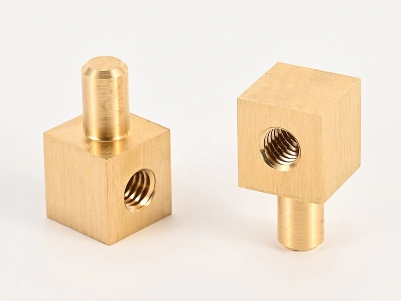
Copper's ductility, thermal behavior, grade variation, and surface sensitivity make process control part of the functional design. A soft or gummy condition can adhere to the cutting edge, change the effective tool geometry, smear at an exit, pull a thin wall, or leave a burr that later breaks away. Chip recutting can mark a contact face, while excessive clamping can distort a compliant section and hide movement until the part is released. A strengthened alloy or harder temper may hold a feature better but increase cutting load, tool wear, heat, or edge damage. C110, C151, and beryllium-copper grades therefore cannot share one assumed cutting response merely because all are copper alloys. Tool sharpness, cutting direction, chip evacuation, work support, roughing allowance, and the point at which the part is unclamped all affect the delivered geometry. The controlling response depends on alloy, temper, product form, feature geometry, tool condition, support, and required finished state; a generic setting cannot be treated as a universal guarantee.
Connectors, terminals, and miniature conductive components make these effects visible because a small burr can disturb insertion or contact, while a scratch, embedded chip, or coating defect can change a current path. A thin section may also move after roughing or unclamping, so an in-fixture check does not always represent the free-state part. Plating, polishing, cleaning, masking, handling, and measurement can further change size and surface condition. The route should state whether critical dimensions and roughness are accepted after machining, deburring, cleaning, plating, or another final operation. It should also define how protected faces travel between operations and how rejected edges are segregated. A quote that lists only machining time may omit the controls needed after cutting, especially when a part moves through outside finishing, multiple setups, or repeat production.
Main Cost Drivers in Copper CNC Machined Parts
Copper part pricing combines material exposure, programming and setup, stock removal, tool access, burr prevention, finish processing, quantity, inspection, handling, and revision risk. Material cost depends on alloy, temper, product form, stock envelope, minimum purchase, yield, and whether certificates or traceability are required. Conversion cost depends on setup count, tool reach, chip clearance, support, deburring access, cleaning, and the number of times a feature must be protected or measured. Electrical or thermal function can add indirect cost because contact faces may need special edge treatment, controlled roughness, masking, plating, or a finished-state report. Quantity changes how programming, fixtures, first-piece evidence, sampling, and inventory exposure are allocated, but volume does not remove a difficult edge or unstable datum. Buyers comparing quotations should ask which driver each line covers, which assumptions are excluded, and whether every supplier is pricing the same revision and acceptance state.
Cost Factor | Decision Impact |
|---|---|
Copper grade and condition | C110, C172, C151, C194, and other grades change stock cost, cutting response, conductivity, strength, certificate needs, and whether substitution requires functional validation |
Part size and stock form | Stock envelope, saw allowance, material yield, straightness, handling, and minimum purchase affect both material exposure and cycle planning |
Geometry complexity | Deep slots, small holes, thin walls, long-reach tools, hidden exits, and multiple datums increase setup, support, tool, and verification risk |
Burr and edge control | Connectors, terminals, hole exits, and contact edges can require directional cutting, support, deburring, cleaning, inspection, and explicit loose-metal acceptance |
Surface finish and plating | Roughness, masking, coating buildup, outside processing, protected transport, and finished dimensions affect route, rework exposure, and acceptance state |
Quantity and demand stage | Prototype, low-volume, repeat, and production lots allocate setup, fixture, sampling, inventory, forecast, and engineering-change risk differently |
Inspection and traceability | Material certificates, dimensional records, coordinate measuring machine (CMM), first article inspection (FAI), roughness, burr, thread, and lot records add evidence cost |
Revision and deviation control | Unclear drawings, silent substitutions, conflicting files, or late changes create reprogramming, rework, scrap, and approval exposure |
How to Reduce Copper CNC Machining Cost Without Affecting Function
The safest cost reduction simplifies the route without weakening the result. Mark contact pads, thermal interfaces, sealing faces, datums, threaded features, plated boundaries, insulation clearances, and prohibited burr locations first. For each marked characteristic, state the functional consequence, acceptance state, measurement method, and owner of any deviation decision. Then review whether nearby tolerances, surface finishes, edge breaks, slots, radii, and cosmetic requirements are tighter than their function requires. A tolerance can be widened only after confirming that assembly stack-up, current density, heat transfer, thread engagement, coating buildup, and inspection uncertainty remain acceptable. Likewise, a roughness requirement should be limited to the faces that actually use it. This separates a documented value-engineering change from a scope deletion that merely transfers risk to assembly, plating, or final inspection.
Buyers can reduce cost by separating conductive contact faces from non-critical surfaces, relaxing non-functional tolerances, selecting a copper alloy that cuts more predictably when conductivity and strength requirements allow it, and avoiding unnecessarily deep narrow slots or very small features. A grade substitution must compare the specified condition, conductivity or thermal duty, strength, joining route, finish compatibility, certificate basis, and service environment; machinability alone is not approval. Edge notes should identify which locations require a controlled break, which must remain sharp for function, and where loose metal is unacceptable. Surface requirements should name the face and the process state rather than applying one finish to the entire part. Requesting comparative pricing at prototype, low-volume manufacturing, and mass production quantities can reveal when a fixture, inspection plan, stock commitment, or process qualification becomes economical across the project path.
A design for manufacturability (DFM) review using DFM for CNC machining should show which setup, tool, handling step, outside process, or report is removed and which characteristic remains protected. The proposal should include the affected drawing feature, old and new requirement, predicted manufacturing change, validation method, and buyer approval owner. A supplier can then connect stock receipt, roughing, stress or movement review, finishing, controlled deburring, cleaning, outside treatment, final inspection, and protective packaging into one route. Savings are credible when that route removes a defined operation or reduces risk without hiding a new assumption.
Burr and Surface Finish Considerations for Copper Parts
Burrs form when ductile copper bends, smears, or tears at hole mouths, slot exits, threads, thin lips, and interrupted cuts. Exit-side support, tool sharpness, cutting direction, feed stability, chip evacuation, and remaining wall stiffness influence whether the material shears cleanly or rolls over. A burr can hold a mating face apart, trap contamination, disturb insulation clearance, damage a thread, obstruct a slot, or shed conductive debris after assembly. Removal can create a second defect if an abrasive rounds a datum edge, embeds media, scratches a contact pad, or changes a thin feature. Define the critical edge, prohibited loose metal, permitted edge break, cleaning state, and inspection method on the drawing rather than relying on a universal deburr note. The process plan should separate prevention from removal and verify the part after the final operation that can create or expose a burr.
Surface finish matters because copper contact, thermal, sealing, bearing, and cosmetic faces do not use texture in the same way. A roughness value alone does not describe waviness, dents, smeared peaks, embedded debris, oxidation, directionality, or the local high spot that changes mating contact. The drawing should identify the controlled face, measurement direction, cutoff or applicable method when required, and whether acceptance occurs before or after plating. Conductive faces should be protected from scratches, dents, contamination, and uncontrolled texture changes between machining and packaging. If plating is part of the process, the pre-plating surface state, cleaning, masking, coating distribution, and buildup can affect final appearance, size, and function. Roughness should therefore be assigned by surface purpose rather than copied across the entire part.
For plating and finish planning, buyers can review 8 common surface treatment process for CNC machined copper parts when deciding which surfaces need protection, conductivity support, wear resistance, solderability, or cosmetic consistency. The final choice still requires an application-specific finish specification, restricted-substance or material requirements where applicable, masking map, contact-area rule, thickness or coverage acceptance, and post-finish inspection state. Buyers should confirm whether thread gauges, slot widths, datums, and mating faces are verified before or after the selected treatment. The outside processor and machining supplier also need a shared revision and a method to trace nonconforming coverage or damage back to the affected lot.
Dimensional requirements should reflect the function of each feature. A contact face, slot width, hole position, or thread engagement area may need tighter control than a non-functional outer edge, but the datum reference and process state must remain consistent. As a non-customer engineering scenario, consider a C110 power-distribution link with two nickel-plated contact pads, a milled fork slot, a mounting-hole pattern, and a thin transition between the current path and the fork. The machining route would protect the pad faces, support the fork during slot finishing, direct the final cut away from the critical edge, and segregate the part through cleaning and plating. Validation would compare free-state hole position, slot width, prohibited loose metal, pad condition, plating coverage, and finished mating fit. The buyer would approve any tolerance or finish relaxation only after confirming that current path, assembly alignment, insulation clearance, and plated contact remain acceptable. Broader guidance on CNC machining tolerances can help separate critical and non-critical copper features before RFQ release.
Risk Area | Control and Verification Decision |
|---|---|
Terminal and connector edges | Protect insertion, contact, insulation, and handling boundaries from burrs, chips, edge roll, and secondary deburring damage; inspect the named edge in its final clean state |
Threads and small holes | Check entry, exit, loose metal, gauge or functional fit, and finished coating condition where applicable; do not use one result to infer the others |
Thin edges and slots | Control support, cutting direction, deformation, tool exit, burr growth, free-state clearance, and the permitted edge-break rule |
Conductive contact faces | Protect against scratches, dents, contamination, roughness drift, embedded debris, and local high spots; verify the actual mating or current-carrying area |
Pre-plating surface state | Verify cleaning, masking, roughness, damage, coverage, buildup, and final dimensions in the required sequence, with responsibility defined across suppliers |
Quality Control for Copper CNC Machined Components
Quality control should prove the conditions that make the component usable, not only show that a few dimensions were measured. Electrical and thermal parts may need evidence of alloy and lot, contact or thermal faces, edge condition, plating, roughness, threads, cleanliness, and finished geometry. The inspection plan should map each critical characteristic to a method, datum, instrument or gauge, sample basis, process state, and acceptance record. Measurement uncertainty, access, fixturing, temperature, surface condition, and part compliance can affect whether a result is meaningful. A coordinate record taken while a thin feature is constrained may not represent its released shape, and an as-machined result may not represent a plated feature. The report package should name the drawing revision, sample or lot, measurement state, method, result, deviation status, and buyer release owner.
A material certificate supports identity and traceability; a dimensional or coordinate measuring machine (CMM) report supports selected accessible geometry; burr, roughness, thread, cleanliness, and plating records support their specific risks. First article inspection (FAI) documents the first agreed route and revision, but it does not replace ongoing lot controls after tool wear, process change, or outside finishing. None of these records automatically proves a different characteristic, and a machine capability statement is not a delivered-part acceptance result. Select the package according to application consequence, process novelty, feature risk, quantity, and demand stage. The buyer should also define reaction rules for a failed characteristic, an unapproved deviation, a material lot change, or a process transfer. Retain enough linked evidence to investigate a repeat-lot issue without relying on an isolated certificate or report.
Quality Control Item | Typical Purpose |
|---|---|
Material certificate | Links alloy, temper, product specification, and heat or lot to delivered parts; it does not verify geometry or surface condition |
Dimensional inspection | Checks listed sizes, positions, datums, and fit-related characteristics using the stated method, sample, and process state |
CMM report | Supports datum-aligned geometry, profiles, positions, and accessible features when fixturing, probing, and part compliance are suitable |
Burr inspection | Controls contact, thread, hole, slot, thin-edge, and loose-metal risk at the named edge and final clean condition |
Surface roughness report | Confirms specified contact, sealing, thermal, or appearance faces using the agreed direction, method, and process condition |
Thread inspection | Checks gauge or measurement results for fastening and plated features in the required finished state |
Plating verification | Confirms finish type, coverage, masking, buildup, adhesion or other specified evidence, and finished geometry where required |
Batch traceability | Connects material, route, tool or process changes, inspection, deviations, disposition, and shipment for repeat production control |
Submit a Copper CNC Machining RFQ
A quote-ready copper RFQ defines more than part geometry. Include the controlled 2D drawing and 3D model, alloy, temper, product form, governing specification, current or heat path, contact and datum map, critical dimensions, burr boundary, roughness and plating sequence, quantity levels, packaging, and inspection evidence. Identify conflicting-file precedence and whether acceptance occurs after machining, deburring, cleaning, outside finishing, or final assembly-related treatment. State mating or functional requirements when they explain why a feature is critical, while keeping proprietary system information to the minimum needed for manufacture. Ask for separate assumptions for stock, setups, tools, deburring, cleaning, outside processing, measurement, certificates, sampling, packaging, delivery, and engineering changes. Supplier questions and approved deviations should be closed against a named revision before production release.
For electrical connectors, terminals, conductive blocks, thermal parts, or other precision copper components, compare quotes by the protected characteristic and evidence supplied, not only by unit price. A useful clarification record states the saving proposed, function preserved, drawing feature affected, validation method, residual risk, and approval owner. Buyers should reject comparisons that silently change alloy condition, acceptance state, inspection scope, plating coverage, or burr criteria. They should also confirm how the supplier controls incoming stock, setup approval, tool wear, deburring, cleaning, outside treatment, nonconformance, final inspection, and protective shipment. This keeps copper CNC machining cost visible while preventing material substitution, finish omission, burr drift, datum mismatch, or inspection gaps from appearing later as rework. The preferred offer is the lowest defensible total route for the required function, not the lowest unexplained unit price.
FAQ