Why is burr control important in copper CNC machined parts?
<h2 id="why-is-burr-control-important-in-copper-cnc-machined-parts?">Why is burr control important in copper CNC machined parts?</h2>
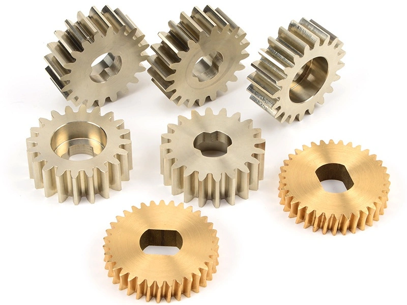
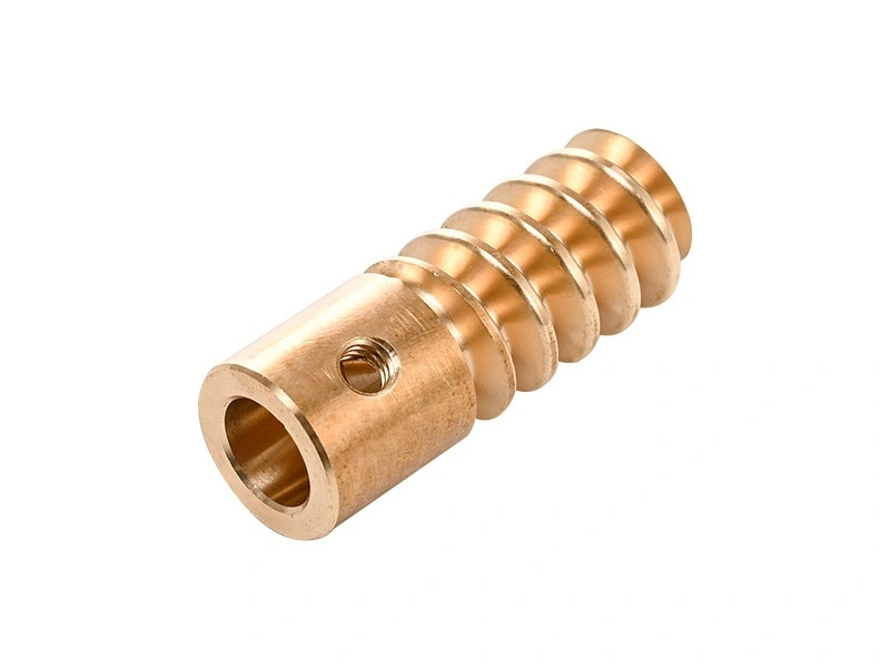
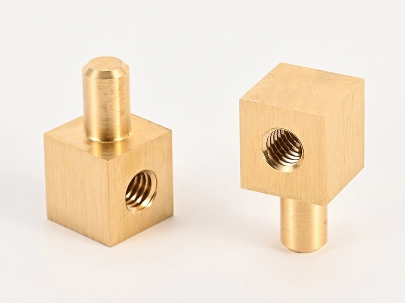
<p><strong>Burr control is important in copper computer numerical control (CNC) machined parts</strong> because a raised edge, loose chip, or smeared lip can change electrical contact, assembly clearance, plating coverage, sealing, and handling safety. Copper's ductility can let material bend instead of separating cleanly, especially at hole exits, cross-holes, slots, thin walls, and interrupted cuts. The buyer should therefore identify functional faces, prohibited burr locations, permitted edge breaks, cleaning needs, and the inspection state on the drawing. Those requirements let a supplier plan tool condition, cutting direction, work support, deburring, finishing, and verification during <a target="_blank" href="https://www.newaymachining.com/services/copper-cnc-machining">copper CNC machining burr control</a>. A general note such as deburr all edges may be insufficient when an edge also locates a part, carries current, receives plating, or must remain sharp for function. Request for quotation (RFQ) and release decisions should use the same feature-level acceptance language.</p>
<div data-type="row" class="row">
<div class="col-12 col-md-6" data-type="col">
<p>
<a href="https://www.newaymachining.com/services/copper-cnc-machining">
<img src="https://www.newaymachining.com/storage/attachments/2026/05/10/copper-cnc-machining-burr-control-copper-machining-burrs.webp" width="750" height="562" loading="lazy">
</a>
</p>
</div>
<div class="col-12 col-md-6" data-type="col">
<p>
<a href="https://www.newaymachining.com/services/copper-cnc-machining">
<img src="https://www.newaymachining.com/storage/attachments/2026/05/10/why-is-burr-control-important-in-copper-cnc-machined-parts.webp" width="750" height="562" loading="lazy">
</a>
</p>
</div>
</div>
<div class="i-typography-table-responsive">
<table>
<tbody>
<tr>
<th colspan="1" rowspan="1">
<p>Feature and Burr Risk</p>
</th>
<th colspan="1" rowspan="1">
<p>Acceptance Decision</p>
</th>
</tr>
<tr>
<td colspan="1" rowspan="1">
<p>Conductive contact face or pad</p>
</td>
<td colspan="1" rowspan="1">
<p>Protect the interface from raised metal, loose chips, scratches, and uncontrolled edge roll</p>
</td>
</tr>
<tr>
<td colspan="1" rowspan="1">
<p>Hole mouth or cross-hole intersection</p>
</td>
<td colspan="1" rowspan="1">
<p>Define accessible and hidden-edge checks before fastening, fluid flow, or cable insertion</p>
</td>
</tr>
<tr>
<td colspan="1" rowspan="1">
<p>Thin wall, narrow slot, or connector edge</p>
</td>
<td colspan="1" rowspan="1">
<p>Limit deformation while preserving required width, clearance, and mating geometry</p>
</td>
</tr>
<tr>
<td colspan="1" rowspan="1">
<p>Edge that will receive plating</p>
</td>
<td colspan="1" rowspan="1">
<p>Set the pre-finish condition, masking boundary, buildup allowance, and final inspection state</p>
</td>
</tr>
<tr>
<td colspan="1" rowspan="1">
<p>Small terminal or insulated assembly</p>
</td>
<td colspan="1" rowspan="1">
<p>Check the insertion path, insulation clearance boundary, loose metal, and handling damage</p>
</td>
</tr>
<tr>
<td colspan="1" rowspan="1">
<p>Sealing, datum, or mating surface</p>
</td>
<td colspan="1" rowspan="1">
<p>Verify that deburring does not create a leak path, high spot, datum shift, or rounded locator</p>
</td>
</tr>
</tbody>
</table>
</div>
<h3 id="1.-burrs-can-directly-affect-electrical-performance">1. Contact interfaces need a feature-specific burr boundary</h3>
<p>A copper contact works through the condition and area of its mating interface, not merely through the bulk conductivity of the alloy. A burr can hold surfaces apart, concentrate contact at a high point, trap contamination, interfere with a spring contact, or shed conductive debris. These risks are different from a cosmetic edge mark. In a non-customer engineering scenario, a copper terminal has a plated contact pad beside a punched insulation barrier and a drilled mounting hole. Its drawing identifies the hole-exit side, protects the pad, and requires a loose-metal and clearance check after plating. The drawing should identify the contact face, adjacent edge, mating direction, permitted edge treatment, and whether inspection occurs before or after cleaning and plating. If the interface is masked, soldered, bonded, or fastened, state that downstream condition as well. The supplier can then protect the face during fixturing and handling, select a cutting direction that moves the exit burr away from the interface, and verify the condition that the assembly will actually use.</p>
<h3 id="2.-small-holes,-threads,-and-thin-edges-are-high-risk-features">2. Hole exits and thin features combine burr and deformation risk</h3>
<p>Small holes, cross-holes, threads, narrow slots, and thin copper edges are difficult because the material at the exit may have little support. A worn edge, recut chip, unsuitable feed, or poor exit support can smear or fold material instead of shearing it. Aggressive hand deburring can then enlarge a hole mouth, round a datum, reduce a thin wall, or damage a thread lead. Review these features as part of <a target="_blank" href="https://www.newaymachining.com/services/precision-machining">precision machining</a> rather than as a final cleanup task. The drawing should separate edges that may be broken from edges that control location, sealing, electrical contact, or fit. Where a hidden intersection cannot be inspected directly, the RFQ should also identify the permitted inspection method or functional check.</p>
<h3 id="3.-burrs-can-also-affect-plating-and-surface-finish-quality">3. Finish sequence determines which burr condition matters</h3>
<p>Plating does not correct an unstable machined edge. A folded lip or loose fragment can remain beneath a coating, create a high-current point, disturb masking, or detach after assembly. Polishing and other finishing steps may also round critical geometry while trying to remove a burr. Define whether machining, deburring, cleaning, masking, and plating occur in that order, and name the state in which each feature is measured. The pre-finish check should catch loose metal and edge damage before outside processing. The final check should confirm coating coverage, finished dimensions, mating geometry, and cleanliness. If a plated thread, hole, or contact pad has a special buildup concern, mark it explicitly. This lets the quote include the correct handling, outside-process communication, and final verification instead of assuming that surface treatment absorbs the burr requirement.</p>
<h3 id="4.-process-control-is-better-than-late-rework">4. Prevent burrs through cutting direction, support, and tool control</h3>
<p>Late rework is costly because the operator may no longer know which edges control function. Prevention starts by reviewing where the cutter enters and exits, how the part is supported, whether chips can leave the cut, and which features are vulnerable to built-up edge. Tool geometry, sharpness, runout, feed, cutting speed, coolant or lubricant strategy, and chip evacuation all affect whether copper shears or smears. The correct settings depend on alloy, temper, product form, tool, machine, and geometry, so the drawing should not invent a universal process value. Instead, define the acceptance result and critical edges alongside the relevant <a target="_blank" href="https://www.newaymachining.com/blogs/understanding-machining-tolerances-what-buyers-must-know-before-ordering-cnc-parts">CNC machining tolerances</a>. The supplier can validate the route on an initial piece and monitor tool condition before burr growth reaches the functional limit.</p>
<h3 id="5.-batch-production-needs-consistent-burr-inspection">5. Production release needs a repeatable edge inspection plan</h3>
<p>A first acceptable part does not prove that burr condition will remain stable through a lot. Tool wear, chip packing, fixture contamination, material condition, and manual deburring variation can change edge results over time. The control plan should identify critical locations, visual access, magnification or tactile restrictions, sample timing, cleaning status, and the person responsible for final release. It should connect the edge check to broader <a target="_blank" href="https://www.newaymachining.com/blogs/quality-control-in-cnc-machining-how-tolerances-surface-finish-and-geometry-are-verified">quality control in CNC machining</a> without replacing feature-level criteria with a generic inspection claim. The <a target="_blank" href="https://www.newaymachining.com/study-cases/custom-copper-cnc-machining-for-industrial-equipment-electrical-connectors-in-high-power-systems">custom copper CNC machining case</a> provides application context, but the buyer's drawing and purchase requirements must still control acceptance. Record deviations and obtain approval before shipping parts outside the agreed edge condition.</p>
<p>For a quote-ready burr requirement, mark every functional contact, hole exit, cross-hole, thin edge, sealing face, datum, and plated boundary that needs special control. State the permitted edge treatment, prohibited loose metal, inspection state, cleaning requirement, sample or report expectation, and buyer release responsibility. Also identify edges that must remain sharp or geometrically intact, since indiscriminate deburring can be as harmful as leaving a burr. Ask the supplier to separate prevention, manual or mechanical deburring, outside finishing, cleaning, and inspection assumptions in the quotation. That evidence makes supplier comparisons meaningful and prevents a low machining price from hiding later rework, assembly interference, coating damage, or functional uncertainty.</p>