Do DFM rules apply to multi-axis CNC machining?
DFM Principles Remain Essential in Multi-Axis Machining
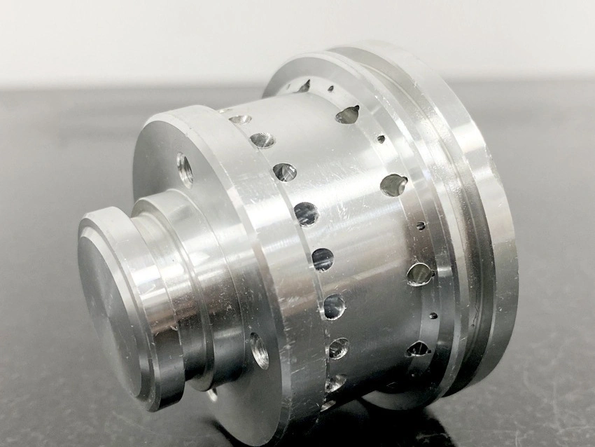
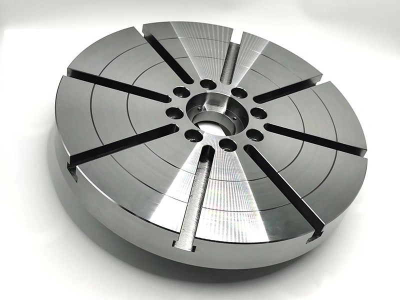
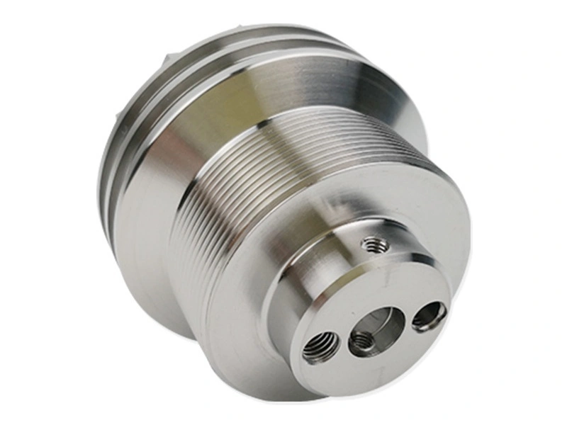
Yes, DFM rules apply to multi-axis CNC machining because additional rotary motion improves access but does not remove limits from cutters, holders, fixtures, datums, materials, or inspection. multi-axis machining may use indexed 3+2 positioning or simultaneous axis motion, and the design must match the intended route. Indexed work can expose several faces while keeping a stable cutting orientation. Simultaneous motion can control tool angle along a contour, but it adds collision, rotary-travel, interpolation, and verification demands. Neither method makes a sharp internal corner, unsupported wall, hidden burr, or inaccessible datum automatically manufacturable. A useful DFM review identifies which surfaces control function, which interfaces must be measured together, and which features need a specific tool orientation. The review should also separate machine reach from process stability: CAM may display a collision-free path while excessive tool stick-out, weak clamping, poor chip evacuation, or blocked probe access makes the cut unreliable. The buyer should provide the controlled model, drawing, datum scheme, material condition, finish zones, quantity, and acceptance method. Early CNC machining feedback can then classify each feature for 3+2 cutting, simultaneous motion, a secondary operation, or a design revision.
Reducing Setup Time and Toolpath Complexity
Multi-axis DFM reduces setups only when one fixture provides rigid support, clear tool and holder envelopes, usable rotary travel, and access for in-process or final measurement. A nominal single-setup plan can fail if a clamp blocks the next orientation, a rotary axis reaches its travel limit, or the chosen datum cannot be probed after roughing. In CNC milling, a narrow deep pocket may still require a long small-diameter cutter even when the machine can tilt toward the feature. In CNC turning, mill-turn access can reduce handling, but slender turned sections may need support and a controlled sequence before cross holes or flats are milled. ISO 230-7 addresses the geometric accuracy of machine-tool axes of rotation; it can support machine verification, but it is not a finished-part tolerance guarantee. Part acceptance still depends on the approved datum structure, tooling, workholding, thermal state, process sequence, and measurement uncertainty. The DFM review should state whether changing a pocket entry, relief, clamp land, or nonfunctional radius prevents a collision, shortens tool reach, protects a datum, or enables inspection. Features beyond stable cutting access may require planned EDM machining or boring, rather than being treated as late rework. Approval should compare those routes on function, evidence, handling risk, and quotation scope.
Material and Cutting Dynamics Considerations
Material choice changes multi-axis DFM because cutting force, heat flow, work hardening, residual stress, burr behavior, and tool wear interact with thin walls and changing tool orientations. Aluminum 7075 can suit high-strength lightweight parts, but the exact temper and stock form matter. Stress-relieved 7075-T651 plate can reduce one source of movement compared with untreated stock, yet it does not prevent a thin wall from shifting after roughing or unclamping. Ti-6Al-4V, concentrates heat near the cutting zone and can form tenacious burrs, so small edges, long engagement, and inaccessible deburring areas need an explicit control plan. Inconel 718 and Hastelloy C-276 may be justified by temperature or corrosion requirements, but complex tool-angle changes can compound rubbing, work hardening, and holder-clearance limits. DFM should preserve blend radii, finishing allowance, and support where those choices keep engagement stable. The RFQ should state grade, specification, heat treatment or temper, stock form, critical wall sections, required roughness, burr limits, and inspection method. A material name without condition and geometry is insufficient for deciding whether multi-axis access will produce a stable part.
Integrating Surface Finishing Within the DFM Process
Surface finishing belongs in multi-axis DFM because coating, material removal, masking, and edge preparation can change dimensions after complex surfaces have been machined. anodizing requirements should identify functional bores, slots, threads, electrical contacts, cosmetic zones, and whether dimensions apply before or after treatment. electropolishing removes material from exposed stainless surfaces, and local removal can vary with geometry and process conditions; sharp edges and narrow transitions therefore need acceptance criteria. PVD coatings and powder coating require explicit masking decisions around bearing seats, mating faces, threads, and small recesses. Continuous blends also need a defined as-machined, polished, or coated state so CAM surfaces and inspection data refer to the same geometry. The buyer should approve finish zones and dimensional state before toolpaths and fixtures are frozen, then specify the post-finish gauges or measurements that release critical interfaces.
Cross-Industry Applications of Multi-Axis DFM
Multi-axis DFM priorities change with product function and acceptance rules, so industry labels cannot replace a feature-level review. In aerospace, weight pockets, thin ribs, heat-resistant alloys, datum stability after roughing, and first-article evidence may control the route. In medical device production, cleanable transitions, burr limits, surface roughness, material documentation, and access for final inspection may be more important than eliminating one setup. Automotive programs may prioritize repeatable fixtures, gauge access, assembly interfaces, and controlled changes across production lots. In every case, the practical question is not whether five-axis motion can reach the shape. The decision is whether the approved process can machine, finish, deburr, measure, and repeat the critical features with the required evidence. Validation may include a prototype cut for the highest-risk wall or blend, a first-off dimensional report, CMM measurement of datum-related features, coating-zone confirmation, and an assembly fit check. The buyer should define which evidence is required before production release and which cosmetic surfaces can use a less restrictive acceptance method.
A complete multi-axis DFM decision records the selected route for every risk-driving feature and keeps the quotation aligned with that route. The RFQ should identify 3+2 or simultaneous motion only when the process is already mandated; otherwise, specify function, geometry, datum, material, finish, volume, and acceptance needs and let the shop propose the route. Ask the supplier to return assumptions for clamp access, tool reach, secondary operations, finishing, deburring, and inspection. Approve model or drawing changes through revision control, then verify that programming and inspection use the same released geometry. This prevents a feasible CAM path from being mistaken for a controlled production process.