4 Axis CNC Milling: Unlocking Precision for Complex Parts

Introduction
4 Axis CNC milling is useful for complex parts when a controlled rotary axis can machine several faces, radial features, or angled surfaces without repeatedly removing the workpiece from the fixture. The process can improve datum control and reduce non-cutting setup time, but only when geometry, material condition, tool access, workholding, finishing, and inspection are planned together. Buyers comparing CNC milling routes should treat 4 Axis CNC milling as a route decision, not a blanket promise of tighter tolerance, lower cost, or faster delivery.
What is 4 Axis CNC Milling?
4 Axis CNC milling adds a rotary axis to the usual X, Y, and Z linear movements so the part can be indexed or rotated to present additional faces to the cutter. Compared with 3 Axis CNC machines, the main value is keeping related features in a controlled setup when the tool can reach them safely. Typical candidates include side holes, radial ports, circular slots, flats around a shaft-like part, angled bosses, and curved surfaces. The route is less suitable when a feature needs continuous five-axis tool tilting, very deep reach, unsupported thin walls, or a finishing process that changes the accepted dimensions.
How It Differs from 3 Axis CNC Milling
In 3 Axis CNC milling, the tool moves linearly while the part usually stays fixed in one orientation until an operator flips or re-clamps it. Each transfer can introduce datum shift, re-zero error, chip contamination on locating surfaces, clamp variation, or burrs that prevent the part from seating cleanly. 4 Axis CNC milling reduces some of that transfer risk by rotating the workpiece under program control. The improvement is practical rather than magical: the fixture must still resist cutting force, the rotary center must be understood, and the inspection plan must confirm the final datum relationship on the drawing.
Types of 4 Axis CNC Milling Machines
There are two main types of 4 Axis machines, and the better choice depends on part length, weight, chip flow, spindle access, fixture design, and inspection requirements:
Vertical 4 Axis Machines: Use a vertical spindle with a rotary table or trunnion-style setup, often around the X-axis. This layout can suit compact housings, brackets, medical components, fixtures, and prototype parts that need side features or repeated angular positions. Check tool-holder clearance, jaw access, chip packing, and whether the fourth axis supports indexing only or true coordinated motion.
Horizontal 4 Axis Machines: Use a horizontal spindle or horizontal rotary arrangement that may help longer parts, heavier workpieces, manifolds, shafts, and components that benefit from gravity-assisted chip evacuation. The fixture can be more complex, but it may keep multiple faces accessible with fewer transfers. Review part weight, support points, rotary centerline, coolant access, and how the shop measures features that span several angular positions.
Advantages of 4 Axis CNC Milling
Enhanced Precision and Accuracy
4 Axis CNC milling can improve feature-to-feature accuracy when several critical surfaces are machined from one datum strategy. The gain comes from fewer re-clamps and better angular control, not from converting machine accuracy into guaranteed part tolerance. A useful engineering example is an aluminum hydraulic manifold with ports on three sides and a sealing face on the top. If roughing movement, clamp marks, port burrs, and sealing-face inspection are controlled, the rotary route may protect port alignment better than separate manual setups. Buyers should ask which dimensions are inspected before finishing and which are accepted after deburring or coating.
Ability to Machine Complex Geometries
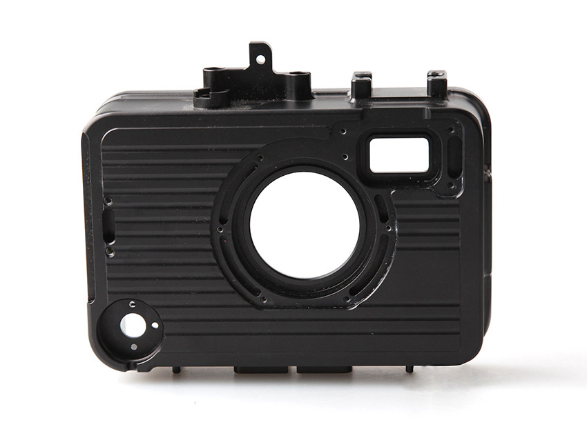
4 Axis CNC milling is strongest on parts where complexity comes from multiple faces around a centerline or repeated angular features. Aerospace turbine-related parts, automation brackets, valve bodies, medical instrument features, and electronic housings may all fit this pattern. The process does not automatically solve every complex surface. Deep undercuts, sculpted surfaces requiring changing tool tilt, narrow internal pockets, and fragile thin walls may still require 5-axis machining, EDM, grinding, turning, or a design adjustment. A good route review separates reachable geometry from features that only look suitable in the CAD model.
Reduction in Machining Time
The time saving usually comes from reducing non-cutting activities: unloading, flipping, re-clamping, re-zeroing, proving another fixture, and repeating manual checks. Cutting time itself may not fall, especially in titanium, nickel alloys, plastics that deflect, or parts requiring conservative finishing passes. A 4-axis route can still be faster overall when it removes setup interruptions and keeps inspection logic simpler. To compare routes fairly, ask for total route time rather than only spindle time. Include programming review, fixture preparation, first-article inspection, deburring, cleaning, and any finishing hold points.
Increased Efficiency in Production Runs
Production efficiency improves when the same fixture, datum plan, tool list, and inspection sequence can repeat across a batch without drifting. For low-volume runs, that may mean fewer setup decisions and more consistent first articles. For higher volumes, the buyer should also review tool wear, fixture wear, chip control, datum cleaning, operator checks, and process-change approval. The fourth axis can reduce variation from part handling, but it can introduce new risks if rotary indexing, clamp force, or tool clearance is not monitored. Efficiency should therefore be measured by accepted parts, not by a faster program alone.
Common Applications and Industries
Aerospace Components
Aerospace components often use 4 Axis CNC milling when light structures, brackets, housings, turbine-related features, or angular holes must maintain controlled relationships between faces. The buyer should define material condition, traceability needs, critical datums, surface finish, burr limits, and inspection reports before quoting. Titanium and nickel alloys add heat-control and tool-wear risk, while aluminum structures may move after roughing or after stress relief. The process can be suitable, but the acceptance plan must separate machine route, drawing tolerance, and final inspection state.
Automotive Parts
Automotive parts can benefit from 4 Axis milling when gearbox housings, brackets, fluid manifolds, valve components, motor housings, or test fixtures need repeated side features. The route can reduce fixture changes and help keep bore, port, and mounting patterns aligned. Cost pressure is usually high, so the supplier should explain whether the rotary setup saves enough handling time to justify fixture preparation. Buyers should also confirm thread gauges, sealing surfaces, burr removal, coating allowance, and whether prototype geometry will transfer cleanly into production.
Medical Equipment
Medical equipment and instrument parts may use 4 Axis CNC milling for angled holes, curved profiles, multi-side features, and small housings that need clean datum control. The manufacturing plan must still address material traceability, edge condition, cleaning, passivation or polishing sequence, and inspection state. For titanium or stainless steel parts, burr control and surface condition can affect function as much as dimensional measurement. A supplier should explain how the route protects functional surfaces and whether any post-machining process changes a critical fit or cosmetic requirement.
Custom Complex Prototypes
Custom complex prototypes often use 4 Axis CNC milling to test geometry before committing to production tooling or a more complex process route. The route can help engineers see whether side features, ports, curved forms, and datum chains work in real material. Prototype speed should not hide unknowns. Buyers should mark which dimensions are functional, which are cosmetic, which can be relaxed for testing, and which must represent future production. That separation prevents a prototype from being priced or inspected as if every feature were already production-critical.
Materials Compatible with 4 Axis CNC Milling
Metals and Alloys
Many metals and alloys can be machined on 4 Axis equipment when the grade, temper, heat treatment, stock form, and finishing state match the planned route. Common candidates include aluminum alloys, titanium, stainless steel, carbon steel, and superalloys like Inconel and Hastelloy. Aluminum usually supports efficient cutting but may move in thin sections. Titanium and nickel alloys require heat, tool-wear, and burr planning. Stainless steels require grade-specific work-hardening and corrosion review. The RFQ should not use a material family name as the whole specification.
Plastics
Engineering-grade plastics including ABS, Nylon, PEEK, Delrin, and Polycarbonate may suit 4 Axis CNC milling when support, temperature, clamping, and measurement timing are clear. Plastics can deflect under clamps, change with moisture or stress relief, and show burrs or cosmetic marks differently from metals. A fourth axis can reduce handling for bushings, covers, rings, and housings, but flexible features may still need soft jaws, staged machining, or functional inspection. State whether dimensions apply immediately after machining, after conditioning, or after finishing and cleaning.
Ceramics
Advanced ceramics, such as Zirconia and Alumina, require the tightest process boundary. Green, partially sintered, machinable, and fired states are not the same manufacturing condition. 4 Axis motion may help angular features or repeated surfaces before final firing or in machinable ceramic states, but fired ceramics may require grinding or a specialist route. The buyer should define ceramic state, shrinkage allowance, edge condition, fracture risk, surface requirement, and inspection method. Do not assume a metal-style milling plan transfers safely to brittle ceramic material.
Essential Surface Treatments after 4 Axis Milling
Post-machining treatments should be chosen according to function, material, datum protection, coating thickness, cosmetic need, corrosion exposure, and final inspection state. They are not just appearance steps. A coating can change a bore, a polishing operation can soften an edge, and heat treatment can move a thin feature. The drawing or RFQ should say whether tolerances are measured before or after treatment, which surfaces must be masked, and which features are critical to assembly or sealing.
Anodizing: Can improve corrosion resistance and wear behavior on aluminum, but anodizing thickness and sealing may affect holes, threads, sliding fits, and cosmetic expectations. Define masking, color requirements, accepted measurement state, and whether critical bores are machined with allowance for the coating.
Electroplating: Can support corrosion, conductivity, or wear requirements when deposit thickness, masking, base material, and hydrogen-embrittlement risk are reviewed. Confirm whether plated features are functional, cosmetic, or both. Threads, sealing faces, and close-fit bores need explicit acceptance rules after plating.
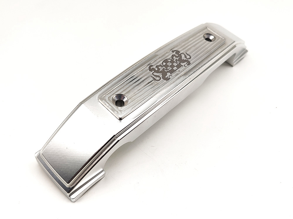
Polishing: Can improve appearance or contact surfaces, but polishing can round edges, change small features, or make burr inspection harder. The RFQ should distinguish visual surfaces from controlled functional surfaces and define roughness targets only when the measurement method and direction are understood.
Powder Coating: Can add protection and color, but coating thickness may reduce clearance, change hole size, and bridge sharp internal corners. Buyers should define masking, coating area, color or texture standard, temperature exposure, and whether mating surfaces must remain uncoated.
Heat Treatments: Can change hardness, strength, stress state, and dimensional stability. The sequence matters because heat treatment before machining, between roughing and finishing, or after machining creates different risks. Specify material grade, target condition, controlled features, and whether final machining or inspection follows the treatment.
Factors to Consider When Choosing a 4 Axis CNC Milling Service Provider
Technical Capabilities and Expertise
Technical capability should be judged by the supplier’s planned route for your part, not by a generic equipment list. Ask for setup count, fixture concept, rotary-axis orientation, collision concerns, tool reach, material-specific risks, and which features may require another process. A capable provider can explain why 4 Axis CNC milling is suitable, where it saves handling, and where it may create access, burr, or inspection problems.
Machine Precision and Software Technology
Machine precision, controller features, probing, and CAD/CAM software can support consistent machining, but none of them replace drawing-based tolerance validation. CAM simulation should include fixture geometry, tool holders, remaining stock, rotary clearance, and likely collision zones. Buyers should ask whether the supplier will inspect the critical datum chain with CMM, gauges, surface roughness tools, or functional checks. The inspection method must match the drawing, not only the machine specification.
Quality Assurance Practices
Quality assurance should define how the part is accepted: first article inspection, in-process checks, sampling level, measurement environment, gauge method, report format, and revision control. ISO-style quality systems can support process discipline, but they do not prove a specific tolerance by themselves. If the part has coating, heat treatment, cleaning, or deburring after machining, the QA plan should state whether measurements occur before or after those steps.
Cost-effectiveness and Project Timelines
Cost and timeline depend on more than machine hourly rate. Fixture design, programming, material availability, tool wear, setup approval, inspection time, finishing sequence, and rework risk all affect the final route. A 4-axis quote may look higher at first but reduce transfers and manual inspection. Another quote may look faster but assume risky tool reach or skip finishing allowance. Ask suppliers to state assumptions, exclusions, and change-control triggers before comparing prices.
Tips for Optimizing Your Design for 4 Axis CNC Milling
Effective CAD Modeling
Effective CAD modeling for 4 Axis CNC milling starts with feature access. Put datum references, angular features, ports, bosses, and critical faces in a model that clearly shows how the part might rotate in the fixture. Avoid hidden assumptions in screenshots or incomplete STEP files. Include the drawing revision, material, stock form, critical-to-function dimensions, and finishing notes so the supplier can test the route before quoting. Add a simple datum sketch when the model alone is unclear.
Material Selection Considerations
Material selection should balance function, machinability, stability, finishing, inspection, and cost. A material that performs well in service may still be difficult to hold, deburr, coat, or measure in a 4-axis setup. Thin aluminum walls may move after unclamping. Stainless edges may burr. PEEK or nylon may shift with conditioning. Nickel alloys may require conservative cutting. Define the exact grade and state rather than asking the supplier to infer from a material family.
Minimizing Complexity to Save Costs and Time
Design complexity should be reduced where it does not serve function. Deep narrow pockets, sharp internal corners, unnecessary angular holes, inaccessible underside features, and over-tight position callouts can add cost or push the job into another process. If a feature is only for clearance or assembly aid, state that clearly. If a tolerance is critical, tie it to the correct datum and inspection method. This helps the supplier protect what matters instead of over-processing every surface.
Planning for Surface Finishes and Tolerances
Surface finishes and tolerances should be planned as one acceptance system. A roughness callout without measurement direction can be ambiguous. A coating without thickness allowance can make a bore undersize. A tolerance stated before finishing may not describe the delivered part. Mark functional faces, cosmetic faces, sealing surfaces, threaded features, and datum surfaces separately. Ask whether inspection reports will reflect the machined state, finished state, or both.
Conclusion
4 Axis CNC milling is a strong option for complex parts when rotary access reduces transfers while preserving the datum relationships that the drawing actually controls. The best candidates have multi-face or radial features, reachable tool paths, stable workholding, a known material condition, and a clear inspection state. The process is not a shortcut around difficult tolerances, poor datum design, or unknown finishing effects. Before release, give the supplier a complete RFQ package with the 3D model, drawing revision, material specification, critical features, finish requirements, production quantity, inspection expectations, and any acceptable alternative routes.
FAQs: