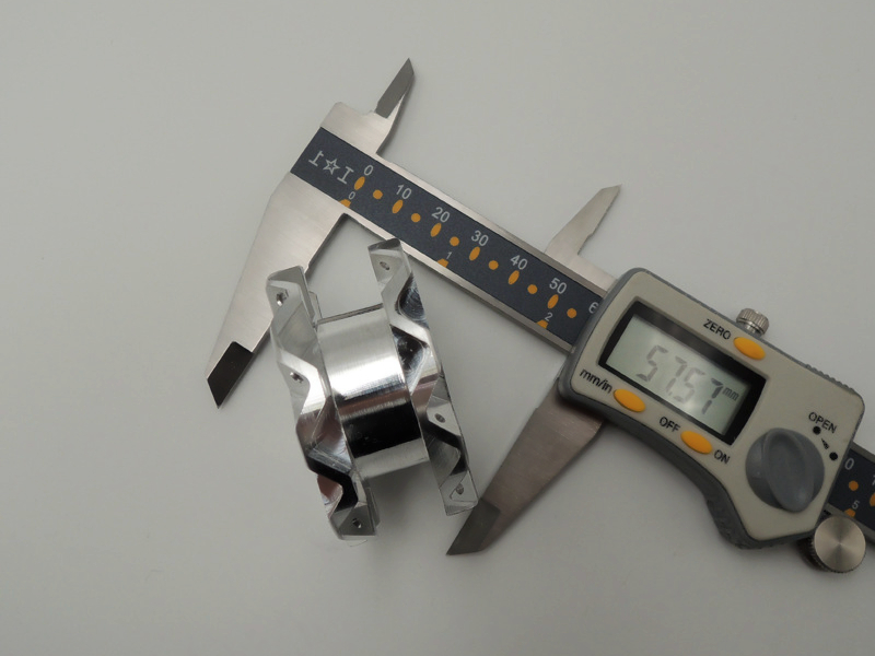
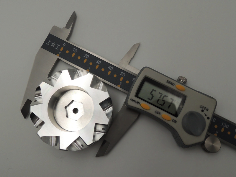
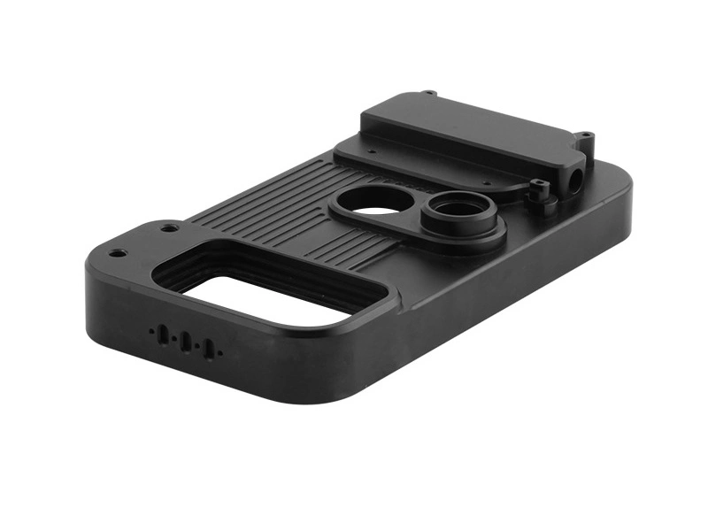
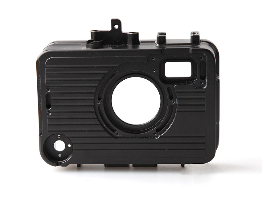
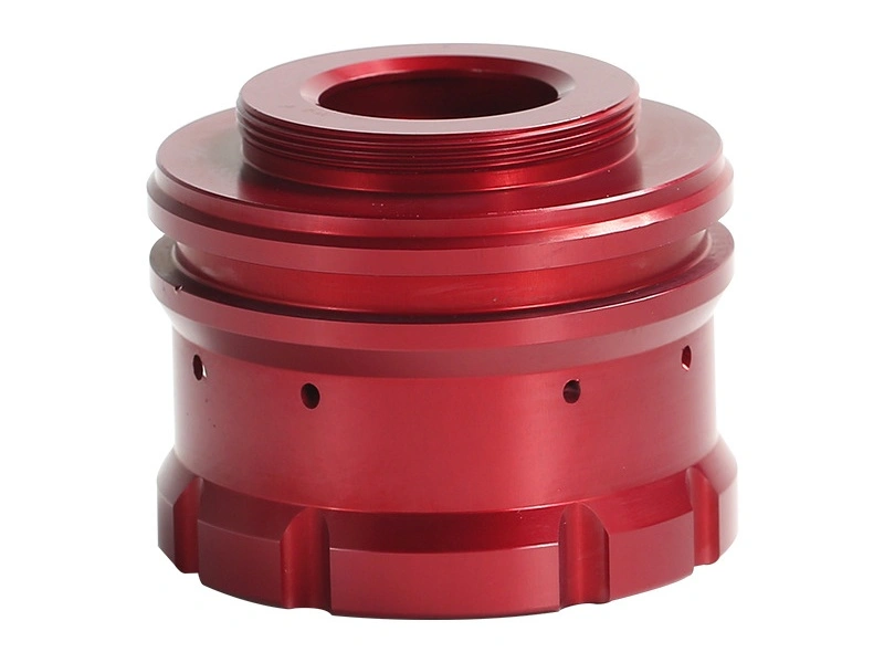
In CNC machining, tolerance decisions should balance function, inspection risk, and cost by assigning tight limits only to features that control fit, sealing, motion, alignment, load transfer, or safety. A blanket tight-tolerance note can make a part more expensive without improving the product. A loose or unclear callout can cause assembly interference, leakage, unstable motion, or an inspection dispute. The useful question is not how tight a machine can cut. It is which feature must be controlled, from which datum, in which material state, after which finishing step, and by which acceptance method. Buyers should provide the controlled 2D drawing, CAD model, material specification, finish condition, critical characteristics, mating requirements, quantity, and reporting level before asking for a final tolerance-cost decision.
CNC machining tolerances are not one number. They include dimensional tolerances, geometric tolerances, surface-texture requirements, and sometimes dimensions that apply only after heat treatment or surface finishing. Dimensional tolerances control sizes such as length, bore diameter, slot width, and thread depth. Geometric tolerances control form, orientation, location, profile, and runout through defined datum relationships. Surface texture can affect friction, sealing, coating preparation, wear, and fatigue behavior, but it does not replace size or geometry. Buyers should review each category separately because each may require a different setup, cutting process, fixture, tool, and inspection method.
Dimensional tolerances define permissible size variation, while geometric controls define how features relate or depart from ideal form. A housing envelope may justify a broader bilateral size tolerance than the bore that locates a bearing, but neither value should come from a generic machine capability statement. Flatness, parallelism, perpendicularity, position, profile, and runout address different failure modes. Surface roughness average, or Ra, describes one aspect of texture; Ra does not prove flatness, waviness, seal performance, or dimensional size. A sealing face can meet diameter and still leak if texture or form is unsuitable. A bearing bore can meet size while clamped and move after release. The drawing should define the inspected state, datum setup, temperature condition when relevant, and acceptance method.
Drawing standards provide interpretation rules, not automatic manufacturing capability. ISO 2768-1 can define general linear and angular tolerances for features without individual callouts when the drawing invokes the applicable class and edition. It should not override a feature that has its own tolerance. ASME Y14.5-2018 defines dimensioning and tolerancing rules, datum references, and feature-control-frame interpretation for drawings that invoke that edition. A contract may instead use an agreed ISO geometrical product specification framework or a customer-specific standard. Buyers should identify the governing document, critical characteristics, material condition, and whether acceptance requires first-article inspection, a CMM report, a functional gauge, or a mating-part test.
Aerospace components made from Inconel 718 may require close feature-level control when a sealing land, bearing seat, actuator interface, or datum relationship governs load transfer or high-temperature alignment. The linked Inconel 718 aerospace CNC machining case provides material and application context. The released drawing, heat-treatment state, stock history, datum scheme, final process, and inspection plan must still define the accepted requirement. A broad aerospace label cannot establish a tolerance for every surface.
Medical devices such as surgical instruments, implants, and ceramic cutting components may need close control on interfaces that govern fit, guided motion, fluid handling, cleaning access, or safe assembly. The linked zirconia ceramic CNC machining for surgical blades is a related process reference, not a universal tolerance rule. Edge condition, brittle-material damage, final surface state, cleaning requirements, and the approved measurement method need separate definition. Dimensional precision alone does not establish biocompatibility or clinical acceptance.
Automotive powertrain parts, robotic assemblies, semiconductor fixtures, and electrical connectors require different controls because their functional risks differ. A valve seat, motor-shaft bore, encoder mount, vacuum interface, or contact location may need a narrower variation band than a cover or clearance pocket. The RFQ should identify the mating condition, operating environment, inspection datum, finish sequence, and whether dimensions apply before or after coating or heat treatment. That information lets a supplier price the critical features without over-processing the rest of the part.
Tolerances affect fit, function, durability, and cost because they control how parts contact, move, seal, align, and transfer load. An interference fit can become loose or impossible to assemble, while a clearance fit can seize, rattle, or leak when its stack is wrong. Geometric relationships may matter more than one size. A bore can satisfy diameter yet misalign an assembly when its position or runout is wrong relative to the functional datum. A sealing surface can fail because of waviness, texture direction, or polishing damage even when its size passes. A complete tolerance plan connects size, geometry, texture, material condition, final processing, and verifiable acceptance evidence.
Tolerance cost rises nonlinearly because a narrower acceptance band reduces process margin and adds control work. Tightening a noncritical milled feature may require an extra finishing pass, a more stable fixture, controlled temperature, and more frequent measurement without improving assembly. A genuinely critical bore or sealing feature may justify boring, grinding, EDM, dedicated gauges, or repeated CMM confirmation. The quoted cost includes more than spindle time. It can include fixture development, qualified tooling, tool-change limits, thermal stabilization, inspection queues, documentation, engineering review, and yield risk. Buyers should ask suppliers to identify which callouts change the route and to quote a function-preserving DFM alternative separately from the released design.
High-precision machining may require multi-axis positioning, controlled roughing and finishing, dedicated grinding, or EDM when geometry cannot be protected in a simple milling setup. A deep pocket, long thin wall, interrupted cut, or superalloy feature can move after roughing or after the fixture is released. The supplier may leave stock for a later finish pass, insert a rest or stress-relief stage when permitted, redesign fixture support, or select another process. The linked bronze CNC-milled steam turbine components page provides a heavy-service machining context. The actual route still depends on alloy condition, feature size, datum access, stock removal, final finish, and measurement conditions.
Tooling becomes a major cost driver when tight tolerances shorten the acceptable wear window. Titanium alloys, nickel superalloys, hardened steels, abrasive ceramics, and copper alloys can require different cutter materials, geometries, holders, coolant strategies, and replacement rules. A tool that remains suitable for roughing may produce taper, size drift, built-up edge, burr changes, or poor texture during finishing. PCD, CBN, ceramic, coated carbide, and special-geometry tools must be matched to the material, machine, setup, and operation. Cost rises when the process needs a dedicated finishing tool, controlled wear limit, preset replacement point, or in-process measurement tied to a defined reaction.
Inspection cost also rises with tighter tolerances because measurement becomes part of process control rather than only final sorting. CMMs, bore gauges, air gauges, optical systems, surface plates, profilometers, and dedicated fixtures answer different questions and have different uncertainty, access, and throughput limits. A first article may require a complete CMM report, while repeat production may use a validated gauge or sampling plan after stability is demonstrated. In applications such as medical stainless steel surgical instruments, the inspection plan should define datum setup, burr and edge criteria, final surface state, and cleaning-sensitive features. Nominal size alone is not enough evidence.
Cost-effective tolerance management begins with a design review that separates functional control from drawing habit. Design for Manufacturability and Design to Cost are useful only when the review names specific features and failure modes. The team should identify datum features, mating surfaces, seal lands, sliding interfaces, bearing bores, fastener patterns, fixture pads, cosmetic faces, and clearance pockets. Close tolerances belong on features that protect product function. General tolerances should cover geometry whose wider variation does not affect assembly, safety, life, or performance. This prevents finishing and inspection effort from being spent on surfaces that cannot change the product outcome.
Functional tolerance zoning is more effective than applying one narrow bilateral tolerance to an entire component. In a medical instrument, the joint surface, guided slot, or locking interface may need close control, while non-mating surfaces can use the governing general tolerance. In an automotive housing, a bearing bore, seal groove, or sensor datum may matter more than exterior ribs. In a robotic bracket, encoder location and bearing alignment can be critical while the outside profile only needs clearance. The drawing should show these priorities through individual size or GD&T callouts, a coherent datum system, and notes that state the final inspection condition. The supplier can then focus setup and measurement effort on real functional risk.
Consider an engineering scenario involving a turbine housing with several datum faces, seal lands, hole patterns, and clearance pockets. If every feature receives the same narrow tolerance, the quotation may include extra finishing, CMM time, and yield risk for surfaces that never contact a mating component. A better review identifies the assembly datum, the seal land that needs form and texture control, the hole pattern that locates a subassembly, and the exterior geometry that only provides clearance. The buyer can request one quotation for the released drawing and one DFM option that relaxes noncritical features. The decision should compare functional validation, inspection evidence, route changes, and production risk rather than selecting the smallest tolerance or lowest price in isolation.
Smart manufacturing improves tolerance control when machine signals, measurements, and corrective actions are tied to named critical features. It cannot make an unrealistic tolerance achievable on an unstable geometry or material. Monitoring may track spindle load, vibration, coolant temperature, probe offsets, tool life, fixture confirmation, and dimensional trends. Those signals indicate possible drift; they do not prove final conformance. The control plan should define an internal action threshold, who reviews it, when production stops, what may be adjusted, and which measurement confirms the correction. Without a reaction rule and independent acceptance evidence, connected equipment produces data rather than reliable tolerance control.
Digital twins and process simulations can predict where tool engagement, heat, deflection, fixture support, or uneven stock removal may shift a feature. In multi-axis machining of complex aerospace or robotic components, simulation can support datum access and sequence planning before finishing. The model must be compared with an unclamped first article and a representative pilot lot. Probing or feedback functions can support a guarded offset for a known drift pattern, but compensation needs tool, axis, feature, and maximum-change limits. An adjustment that recovers one size may move another feature when the shared datum or stack-up is not understood.
Data analysis can improve a tolerance decision by comparing machining history, material condition, tool wear, environmental data, and inspection outcomes. An algorithm does not approve a drawing or replace engineering judgment. Useful outputs are specific risk statements: a thin wall may move after unclamping, a bore may need finishing after thermal stabilization, or anodizing may reduce functional clearance. Each risk should lead to a validation method and buyer decision before price and lead time are fixed. For semiconductor tooling, optical mounts, and precision fixtures, the datum and measurement method may matter more than a headline size tolerance.
Automated inspection can close the loop when CMM results, in-machine probing, and gauge records remain connected to the machining route. This approach can support repeated alignment evidence for precision robotics components, including the linked robotics aluminum CNC milling solutions. The buyer should still define whether inspection applies to the first article, every part, or a statistical sample after the process and measurement system are shown suitable. A credible control loop records the feature, datum setup, measurement method, result, reaction, reverification, and release authority.
Industry examples show why tolerance levels must follow functional risk rather than a generic precision label. The same variation may be necessary on one interface and wasteful on an adjacent surface. A feature review asks what fails when variation increases: leakage, vibration, poor motion, assembly interference, loose fit, electrical contact loss, or an inspection mismatch. That failure mode determines whether the requirement should use a size tolerance, position, profile, runout, form control, surface texture, or a functional gauge. The industry name sets context; the drawing and validation plan set acceptance.
In medical applications, titanium implants, stainless surgical instruments, and ceramic components such as zirconia CNC-machined blades, may need close control on cutting geometry, guided slots, implant interfaces, or fluid-contact features. Tolerance alone does not establish biological compatibility or clinical safety. Material specification, surface condition, cleaning requirement, burr control, passivation or polishing state, and inspection evidence all matter. The RFQ should state whether dimensions apply before or after finishing, which edges have burr requirements, and which surfaces must preserve form or texture for assembly and cleaning.
Semiconductor manufacturing and optical tooling can require stable geometry because small errors may affect alignment, vacuum sealing, wafer handling, or optical positioning. The exact requirement should come from the customer drawing and measurement specification. Flatness, parallelism, profile, position, runout, and surface texture may matter more than one linear size. Temperature, support method, and clamping state can be part of the plan because thin or flexible structures can move between machining and inspection. Buyers should identify whether acceptance uses CMM, optical measurement, interferometry, a dedicated fixture, or a mating-part test and should define how the result relates to the drawing datum.
In automotive and fluid-control systems, housings, valve bodies, motor components, and sealing interfaces may depend on controlled position, runout, flatness, or bore size to manage noise, leakage, wear, and assembly variation. Although the linked automotive titanium CNC machined valve components page concerns oil-and-gas valve hardware, the transferable design lesson is feature-level sealing control rather than an automotive project claim. A bearing bore or valve seat may justify close control. Exterior contours and clearance pockets may not. The buyer should separate safety, fit, sealing, and appearance requirements before releasing the drawing.
These examples show that tolerance selection must be driven by function, material state, process sequence, and inspection method. A narrow tolerance without a datum is difficult to quote and verify. A precise size without surface-texture requirements may not seal. A flatness requirement measured in the wrong support condition can create a false pass or rejection. A finish requirement without dimensional allowance can reduce bore clearance or change thread fit. The design decision is complete only when the stated failure mode, tolerance, final part condition, measurement method, and acceptance action agree.
CNC machining tolerances connect product function, inspection evidence, manufacturing risk, and production economics. The right balance assigns close control to critical interfaces and appropriate general tolerances elsewhere. A complete supplier workflow follows the released datum scheme through stock planning, roughing, any permitted stabilization, final machining, deburring, surface treatment, final-state inspection, reporting, and release. Every transition can change the part or the measurement condition. The drawing and control plan should state which features are protected at each step rather than leaving the supplier to infer acceptance from a small tolerance number.
Future tolerance control will use more process monitoring, digital simulation, measurement feedback, and structured data analysis. These tools can reveal drift, compare pilot-lot evidence, and refine tool-change or inspection rules. They do not promise that any tolerance can be held on any geometry or material. Thin walls can move after unclamping. Finishes can change holes and threads. Tool wear can change burrs, taper, and texture. Better data improves diagnosis and correction, but final acceptance still depends on the drawing, material and process state, measurement system, and authorized release decision.
For buyers and engineers, the next step is to turn the tolerance discussion into RFQ evidence. Provide the CAD model, controlled 2D drawing, critical-to-function list, material and heat-treatment specification, finish sequence, mating requirements, order quantity, inspection report, and acceptance conditions. Ask the supplier to identify tolerance-driven operations, measurement constraints, and the risks behind each cost. Keep a close tolerance when it prevents a defined failure and can be verified in the required state. Relax it only when stack-up analysis or physical validation shows that wider variation preserves the intended function.