How does axis selection affect machining accuracy and lead time?
Which part geometries are best suited for multi-axis CNC milling?
The part geometries best suited for multi-axis CNC milling are those that cannot be machined efficiently, accurately, or economically from only one fixed direction. These typically include freeform surfaces, multi-face precision parts, compound-angle features, deep cavities, narrow channels, thin-wall structures, and rotary or aerodynamic profiles. In these situations, additional axes improve cutter access, reduce setup count, shorten effective tool overhang, and lower the risk of positional error between critical features.
In practical production, multi-axis milling is usually justified when a conventional route would require 3 to 6 separate setups, or when profile continuity, angular accuracy, and surface integrity directly affect part performance. This is why multi-axis CNC milling is widely used for high-value components with complex geometry, and why the comparison between 3-axis, 4-axis, and 5-axis CNC milling becomes important when setup count starts to drive both cost and quality risk.
1. Freeform and Sculpted Surfaces
Freeform geometries are among the best candidates for multi-axis machining because the cutter must stay properly oriented as curvature changes across the surface. These shapes are common in aerodynamic shells, contoured metal covers, advanced mold cavities, and precision functional surfaces.
On a fixed-direction machine, these parts often require long tools, repeated reclamping, and extensive manual blending. Multi-axis motion improves the cutter angle relative to the surface, helping maintain smoother cusp distribution and better contour continuity. When profile tolerance is below 0.05 mm or when surface quality affects flow, fatigue, or optical performance, this becomes a major process advantage.
Geometry Type | Why Multi-Axis Helps |
|---|---|
Freeform curved surfaces | Maintains better tool orientation and smoother contour generation |
Sculpted cavities | Improves access and reduces long-tool deflection risk |
Complex exterior contours | Reduces witness lines and improves surface continuity |
2. Impellers, Blades, and Aerodynamic Parts
Impellers, blisks, compressor-style blades, and other flow-critical parts are classic multi-axis components. Their twisted surfaces, narrow passages, and continuously changing blade angles make them difficult to machine with fixed tool orientation. These parts typically require simultaneous motion so the tool can follow the surface accurately without colliding with adjacent walls.
Because blade thickness may be small and aspect ratios may be high, controlling effective tool length is essential. Multi-axis machining improves rigidity by letting the cutter approach from a more favorable angle, which reduces chatter and protects thin edges. This is one reason these geometries are common in aerospace and aviation applications.
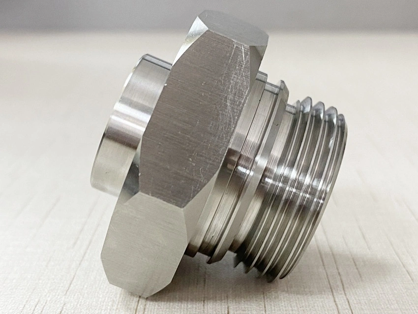
3. Multi-Face Parts with Tight Positional Relationships
Parts with critical features on four or more faces are also strong candidates for multi-axis machining. Typical examples include manifolds, valve bodies, fixture blocks, structural connectors, and housings with intersecting ports or angled reference surfaces.
When these parts are machined on a basic process route, each face may require a separate clamping. Every new setup increases the risk of datum shift, angular mismatch, and cumulative positional error. A 4-axis or 5-axis process can often reduce setup count by 30% to 70%, depending on geometry, which improves spatial consistency between machined features.
Part Feature Condition | Multi-Axis Benefit |
|---|---|
Features on multiple sides | Reduces reclamping and improves spatial consistency |
Intersecting drilled or milled paths | Improves access and preserves datum relationships |
Angular holes and ports | Allows direct machining without secondary fixturing |
4. Deep Cavities and High-Aspect-Ratio Features
Deep pockets, narrow internal channels, and tall walls are often best suited for multi-axis machining when a vertical-only cutting approach would require excessive tool stick-out. Long tools tend to increase deflection, chatter, taper error, and poor surface finish. By tilting the cutter toward the feature, multi-axis machining improves stiffness and cutting stability.
This is especially useful for mold cores, precision inserts, internal flow cavities, and parts with wall depths several times greater than tool diameter. In many real machining cases, even a 20% to 40% reduction in effective tool stick-out can significantly improve finish quality and profile stability.
5. Parts with Compound Angles and Undercut-Adjacent Features
Geometries that combine angled surfaces in several directions are another strong fit for multi-axis milling. These include pockets on sloped faces, beveled sealing surfaces, complex joint interfaces, and features located close to areas that block straight vertical access. Even without a true undercut, these parts can still be inefficient to machine unless the tool can tilt around adjacent geometry.
Multi-axis capability lets the programmer align the cutter with the feature instead of relying on multiple special fixtures. This lowers workaround time, improves accessibility, and often reduces handling cost.
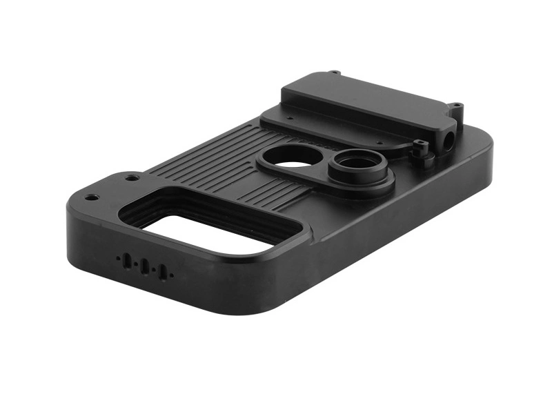
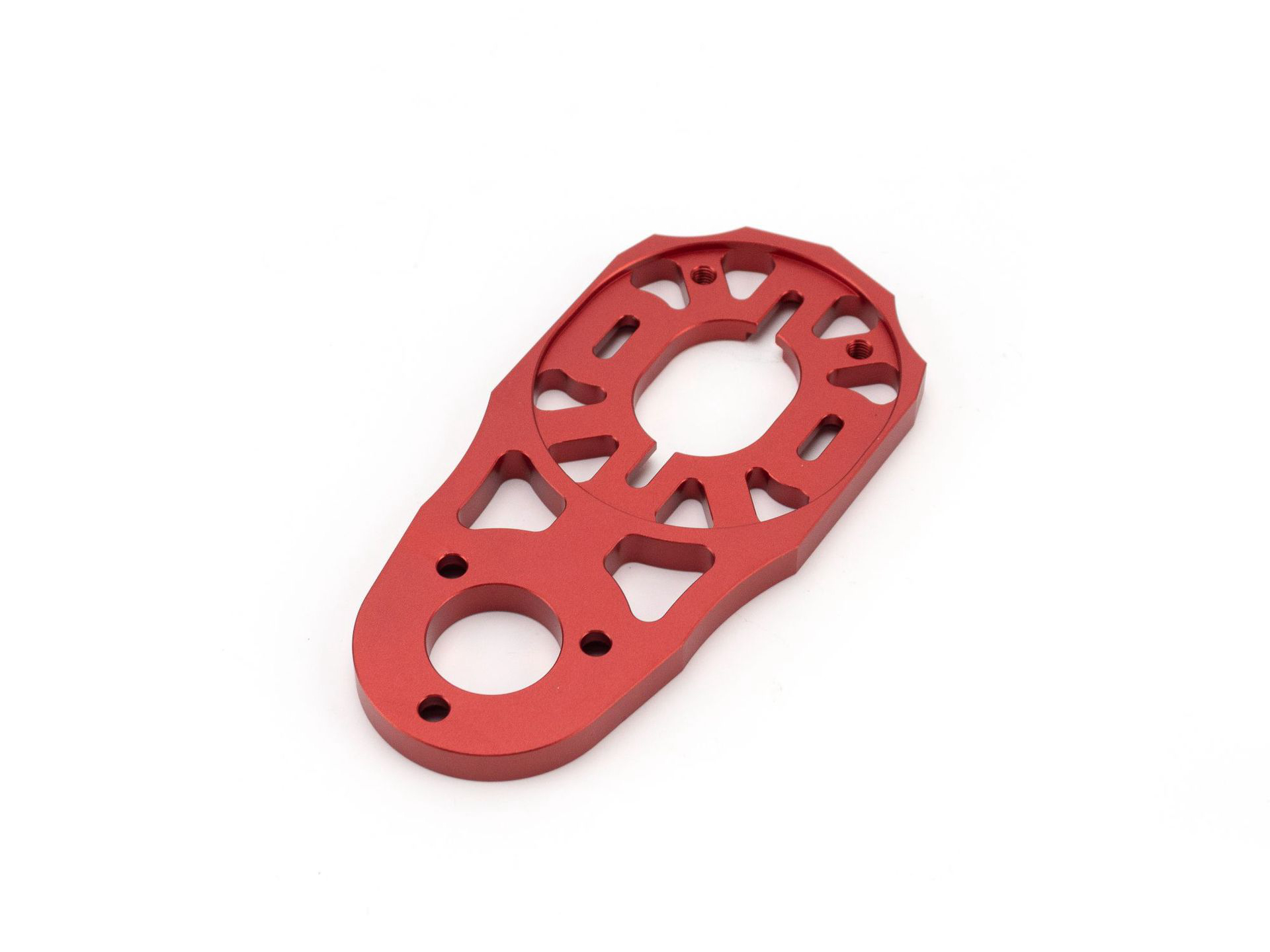
6. Thin-Wall and Low-Rigidity Geometries
Thin-wall metal parts are also well suited for multi-axis milling when they combine low stiffness with complex shape. Examples include lightweight structural ribs, aerospace brackets, frames, covers, and precision shells. These parts are sensitive to clamping distortion and cutting force direction.
Multi-axis machining helps by allowing better tool entry angles and fewer clamp changes, which can reduce deformation during roughing and finishing. When the wall thickness is low relative to unsupported height, controlling force direction is often as important as raw machine accuracy. For high-stability finishing, this is often paired with precision machining.
7. Typical Industries and Part Categories
Industry or Category | Typical Multi-Axis Geometry |
|---|---|
Aerospace | Blades, impellers, structural brackets, complex housings |
Medical Device | Complex implants, contoured surgical components, precision fixtures |
Automation | Multi-face fixtures, angled connectors, precision motion parts |
Robotics | Joint components, lightweight shells, multi-surface mounts |
Industrial Equipment | Valve bodies, flow parts, complex support structures |
These geometry requirements appear frequently in medical device components, robotics assemblies, and industrial equipment parts where feature relationships across multiple surfaces must be controlled in one stable process route.
8. Summary
Best-Suited Geometry | Why Multi-Axis Is Preferred |
|---|---|
Freeform surfaces | Better contour control and surface continuity |
Impellers and blades | Simultaneous angular tool access for twisted profiles |
Multi-face precision parts | Fewer setups and better positional consistency |
Deep cavities | Shorter effective tool length and better rigidity |
Compound-angle features | Direct access without excessive fixture changes |
Thin-wall complex parts | Better force control and lower deformation risk |
In summary, the best part geometries for multi-axis CNC milling are those with complex surfaces, multiple critical faces, difficult access directions, deep or narrow cavities, and tight spatial relationships between features. If a part is mainly flat and prismatic, a simpler machining route is often sufficient. But when geometry complexity begins to drive setup count, tool reach, or contour quality risk, multi-axis machining becomes the more capable and more economical choice.