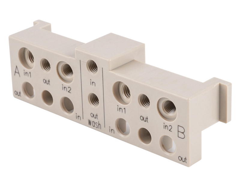
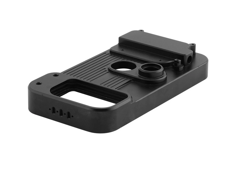
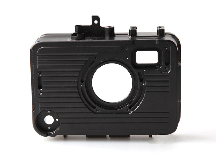
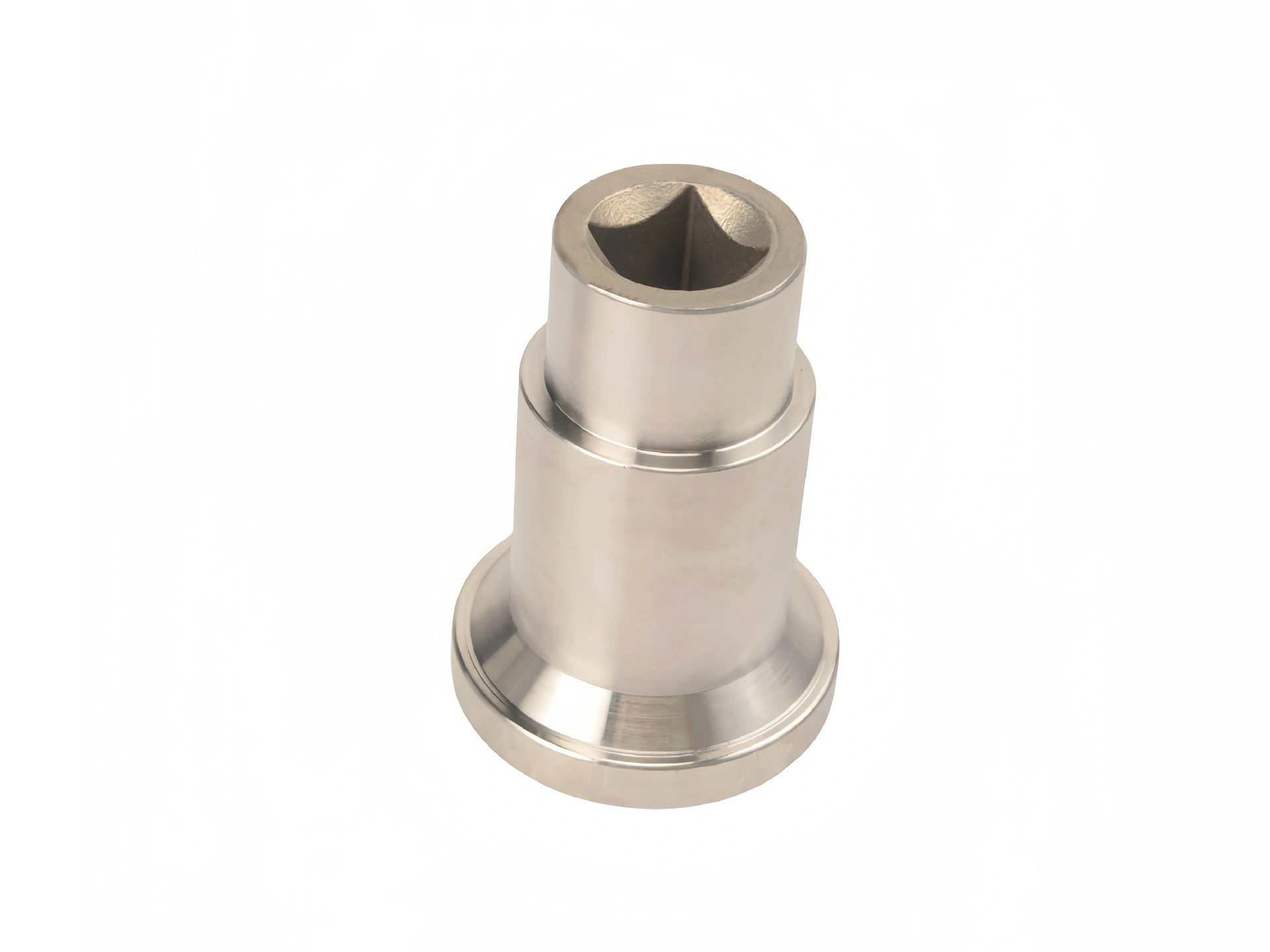
CNC milling plastics can produce accurate functional parts, but tolerance, warping, and surface finish must be planned as linked decisions. POM, PEEK, nylon, PTFE, UHMW-PE, PMMA, ABS, and polycarbonate respond differently to cutting heat, clamping force, moisture, internal stress, and finishing. A simple-looking part can move after unclamping, show burrs on thin edges, or miss flatness after roughing if the exact grade, stock condition, datum scheme, and inspection state are not defined before quoting.
This guide explains how plastic behavior affects milled dimensions, where warping begins, how finish should be accepted, and what an RFQ must contain. The practical limit is feature-specific: a compact bore in stable stock does not behave like a broad thin wall in the same polymer family. Final acceptance therefore depends on geometry, grade, stock form, setup sequence, environment, and measurement method rather than a material name or machine specification alone.
Engineering plastics usually combine lower stiffness, lower thermal conductivity, higher thermal expansion, and greater sensitivity to clamping than common machining metals. Those properties can lower cutting force, yet they also increase the chance of elastic deflection, heat smear, edge damage, and movement after the cutter or fixture is removed. The buyer’s decision is whether the selected grade can hold the required geometry after machining, finishing, storage, and assembly, not simply whether plastic cuts faster than metal.
Key properties influencing plastic machinability include:
Thermal expansion coefficient: Many plastics change size more with temperature than common metals, while fillers and material direction can alter the response within one polymer family. Compare the supplier data for the exact grade, stock form, temperature range, and measurement direction; do not convert a catalog value into a finished-part tolerance.
Low thermal conductivity: Many plastics retain heat near the cutting zone instead of carrying it into the chip or fixture. Concentrated heat can soften edges, smear the surface, increase burrs, or narrow small slots. Sharp tools, clear chip evacuation, controlled engagement, and a suitable finishing pass reduce that risk.
Elastic modulus: Plastics can deflect under clamping and cutter pressure, especially in thin walls, long ribs, unsupported pockets, and flexible sheet stock. A dimension measured while the part is restrained may change after release, so datum selection, restraint state, and inspection timing belong on the control plan.
The machining plan must connect these properties to the part’s function. A flat cover is vulnerable to stress release after broad stock removal. A bearing insert may change at the bore after press-fit. A transparent PMMA window can meet size while failing because of edge chipping, haze, or polishing distortion. Mark the functional risk on the drawing before asking for the tightest available tolerance.
Achievable tolerances in CNC milled plastic parts depend on the feature, not on the polymer name alone. Stiffness, moisture condition, thermal history, wall thickness, feature depth, setup count, datum restraint, and inspection environment can change the result. Tight control is feasible on selected grades and stable geometry, but applying the same narrow tolerance to every face raises setup, inspection, and scrap cost without preventing movement after machining.
Material | Tolerance planning position | Buyer check before release |
|---|---|---|
Acetal (POM) | A practical starting point for compact bores, spacers, gears, and sliding features when the stock is stable and walls remain supported. | Confirm grade, stock direction, finish allowance, unclamped inspection state, and any thin section that could recover after release. |
PEEK | Can support close feature control, but unfilled, glass-filled, and carbon-filled grades differ in stiffness, tool wear, edge behavior, and cost. | Name the exact grade and certificate, then review reinforcement, thermal history, critical face, burr limit, and inspection temperature. |
PTFE (Teflon) | Requires wider planning margins on unsupported bores, thin walls, and loaded dimensions because low stiffness and creep affect cutting and measurement. | Define measurement force, restraint, service load, time after machining, and whether functional clearance matters more than an unloaded size. |
Nylon (PA6) | Must be toleranced in a stated moisture condition because storage, conditioning, machining heat, and service humidity can shift dimensions. | Specify resin grade, conditioning state, storage, inspection timing, service environment, and which dimensions are moisture-sensitive. |
PMMA (Acrylic) | Edge quality, crack prevention, optical area, and post-polish movement may govern the process more than a general dimensional class. | Separate dimensional, cosmetic, and optical acceptance; identify supported edges, visible faces, polish allowance, and crack inspection. |
UHMW-PE | Functional clearances and broad profiles are usually more useful than crisp-edge expectations on large, flexible, or wear-pad geometry. | Review creep, flatness restraint, edge condition, hole function, inspection support, and the assembly clearance required in service. |
Plastic parts with feature-level tight tolerances require a datum and measurement plan that matches how the part will be used. At Neway, the useful discussion for plastic CNC machining services should identify the exact grade, stock thickness, feature type, setup count, restraint state, inspection method, and time between unclamping and measurement. Keep tight requirements on functional bores, sealing faces, datums, and assembly interfaces; use justified clearance or profile limits elsewhere.
Warping begins when residual stress, cutting heat, moisture change, or asymmetric stock removal causes a plastic part to relax into a new shape. A plate, cover, guide rail, or thin housing may pass an in-process check while clamped and fail assembly after release. Prevention requires balanced material removal, appropriate stress management, broad fixture support, controlled cutting heat, and inspection after the part reaches the specified measurement state.
Internal stress release can bend plates, frames, and covers when much more stock is removed from one side. Roughing opposing faces, retaining finish allowance, releasing the part, and allowing redistribution before final cuts can reduce the change.
Excessive cutting heat can soften the surface, weld chips, or create local dimensional change after cooling. Cutter sharpness, engagement, chip clearance, and finishing strategy should be adjusted together instead of slowing every operation by default.
Inadequate fixturing can let the part vibrate, flex, or bow, or it can force a flexible blank flat and hide the error until unclamping. Vacuum fixtures, soft jaws, sacrificial support, and broad contact may be more suitable than isolated clamp points.
Moisture absorption in PA and other moisture-sensitive grades can change dimensions between storage, machining, inspection, and service. The RFQ should state conditioning, packaging, measurement timing, and the expected humidity where the change matters.
Technique | Benefit |
|---|---|
Grade-approved stress relief | Supplier-approved annealing or stabilization can reduce residual stress, but the cycle, support, and dimensional allowance must match the exact resin and stock form. |
Sharp tools with polished flutes | Clean cutting reduces rubbing, heat buildup, burr formation, and surface tearing; tool condition should be checked before critical finishing passes. |
Controlled cutting and chip evacuation | Material-appropriate speed, chip load, engagement, air or coolant strategy, and chip clearance protect the edge without relying on one universal parameter set. |
Consistent clamping force | Documented contact and restraint reduce clamp-induced bow, crushed edges, and datum shifts between roughing, finishing, release, and inspection. |
Controlled material conditioning | Defined storage, drying where supplier guidance requires it, and a stated inspection condition make dimensional results relevant to the service environment. |
Consider an illustrative thin cover with pockets concentrated on one side. A controlled route may rough opposing faces, retain finish stock, release the part, allow stress to redistribute, then finish the datum face and critical pockets in a supported setup. Validate flatness or profile after unclamping and after the specified stabilization interval; an in-fixture dimension alone cannot confirm the released shape. The buyer should include this sequence when prior samples have passed machining checks but failed fit.
Surface finish in milled plastic affects appearance, sealing, sliding, cleanliness, optical clarity, coating adhesion, and burr control. A roughness value alone is insufficient because equal Ra readings can accompany different tool direction, heat smear, whitening, chatter, edge damage, or manual deburring marks. Buyers should identify cosmetic faces, functional contact areas, optical zones, inspection direction, and edges that cannot retain loose burrs.
Finish Type | Acceptance basis | Description |
|---|---|---|
As-machined | Define permitted tool marks, direction, burr condition, and any functional roughness measurement on the critical face. | Suitable for hidden or non-sealing features when cutter marks do not affect fit, cleaning, friction, or assembly. |
Polished | Define whether the goal is cosmetic appearance, sealing, low friction, or optical preparation, then inspect dimensions after polishing. | Polishing can reduce visible marks but may round edges, alter small holes, expose stress, or change transparency. |
High-gloss | Qualify the exact resin and finishing route, then state visible area, lighting, haze or transmission test, and allowed edge defects. | Most relevant to selected PMMA or PC parts; high gloss and optical performance are separate acceptance decisions. |
PMMA and PC can support flame, vapor, or mechanical polishing only when the selected method is compatible with the grade, wall section, stress state, and optical requirement. UHMW-PE and PTFE tend to retain a waxy or matte appearance, so cosmetic polishing may add cost without improving function. For painted, bonded, or plated parts, surface preparation must support adhesion and cleanliness as well as appearance.
Selection of plastic surface treatments should start with the resin, service condition, visible area, and dimensional risk:
Painting: Can provide color, appearance, or UV protection when cleaning, surface preparation, primer, and coating compatibility are qualified for the exact resin.
Polishing: Can serve covers, lenses, windows, and visible components, but the finishing route must protect optical zones, critical edges, holes, and datum surfaces.
Electroplating (on ABS): Requires an approved plateable grade, surface activation, conductive seed layer, coating stack, rack plan, and adhesion validation; machined ABS is not approved by name alone.
UV coating: Can add surface protection to compatible PC or PMMA, provided cure conditions, coating thickness, optical effect, and assembly clearances are verified.
A surface treatment can introduce cracking, crazing, swelling, delamination, coating peel, rounded edges, or hidden dimensional change. The RFQ should identify the finish supplier or approved system, visible face, masking, protected datum, coating thickness concern, adhesion or optical test, and whether acceptance occurs before or after finishing.
The right plastic depends on mechanical load, operating temperature, friction, chemical exposure, electrical behavior, regulatory needs, optical requirements, and the tolerance map. Polymer names are only a screening level; grade, filler, stock form, conditioning, and supplier data determine the relevant properties and machining response. Use the table to identify the next confirmation, not to replace a material specification.
Material | Grade and stock checks | Key Features | Ideal Applications |
|---|---|---|---|
POM (Acetal) | Confirm homopolymer or copolymer, filler, stock form, color, certificate, and stability of the supplied blank. | Low friction, useful dimensional stability, clean cutting, and wear behavior for supported moving features. | Gears, bushings, rollers, spacers, bearing blocks, sliding details, and functional prototypes with controlled load and temperature. |
PEEK | Confirm unfilled or reinforced grade, certificate, stock history, required temperature performance, and tool-wear implications. | Heat and chemical resistance with useful stiffness and strength, balanced against high stock cost and grade-specific machining behavior. | Medical, aerospace, energy, semiconductor, and high-performance fixtures where the specified grade is validated for service. |
PTFE | Confirm virgin or filled grade, compression and creep limits, measurement support, and the loaded service condition. | Low friction and broad chemical compatibility with low stiffness, creep, and limited support for tight structural dimensions. | Valves, seals, chemical-processing parts, low-friction liners, and components designed around compression behavior. |
Nylon 6 | Confirm grade, reinforcement, conditioning state, moisture exposure, dimensional state, and impact or wear requirement. | Toughness, impact and wear performance, and moderate stiffness with moisture-dependent dimensions and properties. | Wear parts, housings, rollers, guards, and mechanical details where humidity and dimensional change are addressed. |
UHMW-PE | Confirm molecular-grade specification, stock flatness, wear requirement, creep allowance, and functional clearance. | Wear and impact performance with low friction, high toughness, flexible stock, and difficult crisp-edge control. | Linings, slides, wear pads, conveyor parts, guide rails, and impact surfaces where close edge geometry is secondary. |
PMMA (Acrylic) | Confirm cast or extruded stock, color or optical grade, stress state, visible area, edge finish, and polishing route. | Optical clarity, UV stability, and appearance with brittle edges and sensitivity to support, heat, and incompatible chemicals. | Display windows, light guides, shields, covers, and visible components with explicit optical and edge acceptance. |
The linked CNC plastic machining service is relevant only after the exact material and functional boundary are defined. POM can be a practical starting point for stable mechanical features, PEEK for qualified heat or chemical service, PMMA for transparency, PTFE for low-friction chemical contact, nylon for tough wear parts, and UHMW-PE for sliding or impact surfaces. Final selection still requires grade data, drawing review, and sample validation where failure would affect assembly or service.
A useful plastic milling RFQ separates functional dimensions from cosmetic preferences and identifies features likely to move. A STEP file alone does not define datum restraint, acceptance after unclamping, thread load, service temperature, humidity, optical quality, burr limits, or whether flatness is checked before or after assembly. Those inputs determine whether the supplier can plan machining and inspection around the actual failure risk.
Use looser tolerances where precision is not functional, while retaining justified control on bores, datum faces, sealing surfaces, optical zones, and assembly interfaces.
Avoid sharp internal corners where possible because small cutter radii, interrupted engagement, stress concentration, and limited chip space can raise cycle time and burr risk.
Design consistent wall thickness or identify unavoidable asymmetry so roughing, support, stabilization, and final inspection can address stress release.
Incorporate radii on pockets and channels that permit suitable tools, stable engagement, chip evacuation, and lower heat concentration at deep corners.
Avoid deep narrow slots unless function requires them; thin tools, poor chip clearance, and flexible walls can produce taper, chatter, burrs, and dimensional drift.
A DFM (Design for Manufacturability) review should connect material grade, stock conditioning, roughing sequence, datum strategy, tool access, fixture contact, deburring, surface treatment, and final inspection. Record which dimensions are checked while supported, which are checked after release, and which must remain valid after finishing or conditioning. This supplier workflow prevents each production step from optimizing its own result while shifting risk to the next operation.
Plastic CNC milling is suitable for housings, insulators, wear pads, prototype covers, fixtures, transparent windows, and high-performance polymer components when material behavior matches the drawing. Cutting heat, clamping, residual stress, moisture, burr formation, and post-machining movement explain many tolerance, warping, and finish failures. Before release, specify the exact grade and stock form, datum scheme, critical features, restraint state, surface acceptance, conditioning, and inspection timing.
A supplier discussion with Neway should connect the required function to material selection, workholding, roughing and finishing, deburring, surface treatment, and measurement. State whether the part needs released flatness, optical performance, low-friction wear, thread strength, chemical resistance, or high-temperature service before quoting. The right plastic is the grade that can be machined, finished, measured, and assembled under defined conditions without hidden rework after the first sample.