How do I prevent warping in thin plastic components?
How Do I Prevent Warping in Thin Plastic Components?
Reduce warping in thin CNC-milled plastic components by controlling the exact stock state, balancing material removal, limiting cutting heat, supporting the part without forcing it flat, and inspecting after release and stabilization. No method guarantees zero movement because residual stress, moisture, temperature, geometry, and time remain material-dependent. Buyers should define the functional flatness or profile, datum state, service environment, and when the result must conform. A trial should compare material control, machining sequence, and free-state recovery before the production route is released.
1. Select and Characterize the Stock
Warp control starts with the actual blank, not a resin-family reputation. Record the exact grade, reinforcement, stock manufacturing route, thickness, material direction when relevant, annealed or conditioned state, storage history, and supplier data. Inspect blank flatness and thickness before machining. If blanks from different lots show different initial bow or recovery after a skim cut, treat stock condition as a process variable. Do not promise a flat finished part from material identity alone.
Evaluate POM (Acetal) or PEEK only in the specified grade, stock form, section, and condition. Their suitability must be shown on the released geometry and final-state inspection.
Do not automatically reject Nylon or ABS. Define moisture, temperature, stock stress, wall support, assembly clearance, and inspection timing, then decide whether the trial evidence meets the intended use.
2. Condition Stock to a Defined State
Drying and conditioning are not interchangeable, and neither has one universal cycle. Follow written guidance for the exact resin grade, reinforcement, stock form, section, and intended state. Record equipment, temperature profile, duration or equilibrium criterion, cooling, storage, and elapsed time before machining and inspection. If service behavior depends on moisture, inspect the agreed conditioned state rather than an arbitrary dry state. Reject any proposed temperature or time that lacks traceable material-supplier support.
3. Balance Material Removal and Observe Recovery
A balanced sequence removes stock from opposing faces in controlled stages, leaves route-specific finishing allowance, and observes movement after each release. Rough both sides evenly only where the geometry and datum plan support that strategy. Symmetry in toolpaths does not guarantee equal stress release from an asymmetric blank or part. Record bow or profile after roughing, after unclamping, after the agreed rest condition, and after final sizing. Use those measurements to adjust the next trial, not a generic allowance.
4. Control Cutting Heat at the Source
Use sharp, grade-compatible cutters with geometry and edge preparation selected for clean shearing. Monitor burrs, smearing, chip form, wall deflection, and tool condition during trials.
Select spindle speed, feed, engagement, depth, toolpath, and pauses from cutting tests and supplier guidance. Slowing the spindle alone can increase rubbing if chip load becomes unsuitable.
Use air blast or coolant only after checking resin compatibility, stress-cracking risk, moisture effects, cleanliness, finish, and disposal requirements for the released process.
More info: Plastic CNC Machining
5. Support the Part Without Hiding Distortion
Workholding must resist cutting forces without bending the blank into a false datum. Map clamp or vacuum load, support locations, cut-through areas, leakage paths, local contact pressure, and release sequence. Verify the part both in the machining state and free after unclamping. A fixture can improve cutting stability while concealing stored deflection. For windows, flexible frames, and interrupted walls, support the remaining load path as material is removed and check that support does not mark functional surfaces.
Vacuum fixtures can support broad areas when sealing, leakage, cut-through, suction distribution, and release deformation are validated for the actual geometry.
Custom soft jaws or sacrificial plates can distribute load when their contact map, relief, cleanliness, and datum relationship match the intermediate and final shapes.
Low-force workholding means the minimum verified load that prevents movement during cutting. It is not a fixed pressure and must be validated against slip and free-state recovery.
6. Separate Roughing, Recovery, and Final Sizing
Choose roughing allowance from the exact stock thickness, remaining wall, geometry, cutter, fixture, observed movement, and finishing method. No universal allowance applies to every thin plastic part. After roughing, release the part and measure at defined intervals under the agreed temperature and moisture state. Finish critical features only after the recovery trend meets the process criterion. Recheck after final unclamping and before packing; an in-fixture result cannot establish free-state flatness.
Example: Thin Polycarbonate Cover Plate
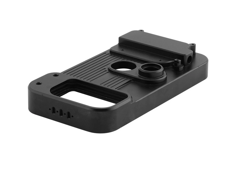
Consider a hypothetical polycarbonate cover with a long window, screw bosses, optical zones, and a sealing edge. Define the exact grade, stock route, cosmetic reference, stress-cracking controls, assembly support, and free-state profile first. Trial alternative blank orientations, support maps, and balanced roughing sequences while holding inspection conditions constant. Measure profile, hole position, optical distortion, cracks, and assembly clearance after release. Select the route that meets all named criteria; do not generalize its result to another thickness, grade, or window geometry.
Manufacturing Services You May Need
Submit the thin-part warpage RFQ through plastic CNC machining. Treat the linked POM, PEEK, and polycarbonate references as material-specific inquiry routes, not proof of dimensional stability. Include material records, blank map, CAD and drawing, unsupported spans, datum and support state, process candidates, service environment, measurement schedule, acceptance rule, quantity, and revalidation triggers. Require free-state results from the actual trial before accepting a production claim.
Before production release, confirm which surface must conform after unclamping, how long and under what environment it stabilizes, and what change will trigger another trial.