Non-Destructive Contour Testing for CNC-Finished Components
The Core Value of Non-Destructive Contour Testing in Modern Manufacturing
Non-destructive contour testing verifies the external or internal geometry of CNC-finished components without cutting, sectioning, or damaging the part, and it is most valuable when shape, datum relationship, or hidden features affect assembly release. The method is not one single machine. It can include structured-light scanning, blue light scanning, laser scanning, tactile CMM checks, form measurement, industrial CT, on-machine probing, or a hybrid plan. The buyer’s main decision is to choose which contour evidence governs acceptance: full-surface deviation, datum-based GD&T, hidden internal geometry, or process feedback before the next machining step. A contour report should therefore answer three questions. Which geometry was measured, how was the measurement aligned, and what action follows if the result conflicts with a critical feature check? The most common mistake is treating a dense point cloud as complete proof of conformity. Dense data still needs a datum rule, uncertainty boundary, surface condition record, and reviewer decision.
In the aerospace sector, contour inspection of aero-engine components must separate surface trend data from release-critical features because blade profile, sealing faces, datum bores, and thermal growth can fail in different ways. In medical implant machining, the same testing logic protects fit, surface integrity, and traceable documentation without assuming that every optical method is suitable for every polished or curved surface. A useful RFQ should include the CAD model, 2D drawing, datum scheme, CTQ features, material condition, finish state, cleaning limits, tolerance range, and required report format. The buyer should also state whether the inspection result controls shipment, first article approval, process correction, or only engineering reference. Without those inputs, a scan may look detailed but still fail to answer the buyer’s release question. A good inspection plan also defines what the page does not decide. It should not replace destructive material testing, fatigue validation, coating qualification, or functional assembly trials when those checks control the final product risk.

Blue Light 3D Scanning: Principles, Accuracy Boundaries, and Best Use
Blue light 3D scanning projects structured light onto a visible surface and reconstructs the surface from camera triangulation, so it is strongest when the inspection question needs a dense contour map. The advantage is coverage, not an automatic tolerance guarantee. Scan quality depends on equipment calibration, camera angle, target distance, lighting, surface reflectivity, fixture stability, software alignment, and the part’s size. Optical performance may be checked with methods such as VDI/VDE 2634 when applicable, but the finished-part decision still depends on the actual measurement plan. Buyers should ask whether the scan uses best-fit alignment, datum-based alignment, or local feature alignment before using the color map for acceptance. Best-fit alignment can hide a datum shift, while datum alignment can make surface variation look larger. The report should explain which view is used for release. It should also describe how missing points, edge bloom, glare, smoothing, and hole filling were handled. Those processing choices can change the visible deviation pattern even when the physical part has not changed.
For blue light 3D scanning services applied to five-axis machined impellers, the strongest use case is comparing blade surfaces, leading-edge trends, root blend continuity, and machining allowance against CAD. In an automotive turbocharger impeller scenario, a dense scan can show whether profile error concentrates near a toolpath transition or near a flexible blade tip. That evidence is useful for process correction, but the supplier should still confirm datum features and critical bores with a method suited to those features. For aluminum alloy parts with complex freeform surfaces, optical scanning is efficient when burrs, glare, anodizing state, and unclamping movement are controlled. A thin wall can move after fixture release, and a polished surface can create missing scan data. Those two failure modes require different controls, so one generic scanning plan is not enough. The RFQ should identify the inspection side, visible line-of-sight limits, allowed surface preparation, and whether a secondary CMM check is required for functional datums.
Industrial CT for Hidden Internal Contours
Industrial computed tomography can inspect internal contours by capturing X-ray projections and reconstructing the part’s internal volume, so it is useful when the feature cannot be reached by a probe or seen by an optical scanner. CT is not a universal replacement for CMM or optical scanning. Voxel size, material density, wall thickness, beam-hardening artifacts, part size, fixture orientation, and the contrast between adjacent materials control what can be measured. CT may reveal hidden channels, trapped powder, internal ribs, wall variation, porosity, or assembly interference, but the buyer should define which internal geometry is actually critical before paying for a high-volume scan. CT data also needs threshold rules. A different threshold can change an edge, a wall thickness value, or the apparent position of an internal channel. Metal parts with thick sections may need stronger artifact control than plastics or thin-wall components. Mixed materials, inserts, and sharp density changes can reduce confidence in small dimensional readings.
In high-precision injection mold manufacturing, industrial CT inspection may help verify conformal cooling channels when the drawing defines channel location, minimum wall distance, and allowed deviation from the cavity surface. The useful question is not only whether the channel exists. The practical question is whether the channel path supports thermal balance without breaking through, thinning a wall, or creating a blocked section. For stainless steel 316L medical components with hidden cavities, CT can support non-destructive verification when sectioning would destroy the part. The report should state scan resolution, artifact controls, reconstruction settings, inspected region, and any features excluded from reliable measurement. If the drawing tolerance is close to CT uncertainty, a sectioned sample, CMM reference feature, or alternative validation route may still be needed. Buyers should request a clear distinction between visualization for engineering review and dimensional measurement for release.
Five-Step Implementation Process: From Inspection Plan to Report
A reliable non-destructive contour testing workflow starts with an inspection plan, not with scanning speed. Step one defines the functional question, datum scheme, CTQ features, material state, surface state, tolerance range, and report format. Step two prepares the part through cleaning, fixture selection, thermal stabilization, reference target placement, surface preparation, and calibration checks. Step three captures data by the chosen method, such as optical scanning, tactile points, CT volume, tracker reference, or on-machine probing. Step four aligns and filters the data under a stated rule. Step five reviews deviations against the drawing and records the release decision. Each step needs an owner, because late disagreement about alignment or filtering can force a complete reinspection. The plan should also define a hold point for suspect results. If a critical deviation appears, the supplier should know whether to rescan, confirm by another method, or stop for buyer review.
For parts with complex machined surfaces, the workflow must also connect machining history to inspection interpretation. Roughing may leave residual stress that moves after unclamping. Finishing may shift a thin wall. Deburring may change an edge that the scanner sees but the assembly does not use. Coating or polishing may reduce a bore size or hide a small burr. A supplier should therefore define whether inspection occurs before deburring, after finishing, after surface treatment, or at more than one stage. The report should identify the equipment used, calibration status, alignment method, software version, filtering rule, excluded areas, and reviewer approval. The buyer should request a sample report before approval when the project uses a new inspection route or a tight profile tolerance. That sample report can reveal whether the supplier understands the difference between surface trend evidence and release-controlled dimensions.
Application Scenarios: Impellers, Molds, and Medical Components
In titanium alloy impeller inspection, non-destructive contour testing is useful because blade profile, twist, thickness distribution, leading-edge condition, and root blend geometry affect performance and inspection access. A practical engineering scenario is a five-axis impeller that scans within the overall envelope but shows a local high spot near the blade root. The buyer should not accept or reject the part from a color map alone. The inspection team should check whether the deviation is tied to datum alignment, tool deflection, finishing pressure, or a real surface error. If the high spot affects airflow or clearance, the release decision should use the drawing tolerance and functional datum scheme. If the deviation only reflects nonfunctional stock left for a later finishing cut, the same scan becomes process feedback rather than rejection evidence. The same part may need a full scan for blade form and a point-based check for shaft or bore relationship.
For precision molds, contour testing should focus on cavity surfaces, parting lines, shutoff faces, ejector-related surfaces, cooling-channel clearance, and areas that affect flash, sink, or assembly fit. A mold may pass a broad surface comparison while failing a local shutoff face that controls leakage. For medical components, the critical boundary is different. The method must protect surface integrity, cleanliness, traceability, and biocompatibility-related requirements while still measuring anatomical or assembly geometry. Temporary scanning spray, contact force, polishing residue, or CT artifact can become part of the risk assessment. The buyer should identify which surfaces are functional, cosmetic, clean-critical, or only reference surfaces before selecting the inspection route. This prevents an inspection plan from optimizing scan speed while missing the surface that actually controls patient fit or assembly reliability. The decision should be recorded before inspection, because a supplier cannot fairly judge data quality after the acceptance target has moved.
Comparing Inspection Data with CAD Models and Datums
Scan data becomes useful only after it is aligned, filtered, interpreted, and compared with the correct CAD and drawing revision. Best-fit alignment can reveal general shape error across a surface, but it can hide a datum shift that matters in assembly. Datum-based alignment is stronger for release when GD&T controls how the part locates in the product. Local feature alignment can be helpful for diagnosing machining behavior, but it should not govern final acceptance unless the drawing or inspection plan says so. The report should state alignment type, inspected features, tolerance interpretation, software settings, and any smoothing or hole-filling rule used before deviation maps are generated. The report should also separate accepted deviations, rejected regions, and unresolved measurement uncertainty. Surface roughness should not be confused with contour error. A rough surface can add scan noise, while a true contour deviation shows a repeatable geometric trend.
In first article inspection services, the most valuable output is not a colorful image. The value is a decision trail that connects deviation patterns to machining causes and buyer actions. A repeated contour offset may indicate tool length compensation, fixture shift, thermal drift, or CAD revision mismatch. A local edge deviation may come from burr formation or polishing. A thin-wall wave may appear only after unclamping. The buyer should ask whether suspect zones were remeasured, whether datum features were confirmed separately, and whether the inspection result is suitable for prototype learning, FAI release, or production control. The same raw scan can support different decisions, so the report must state the intended decision before the deviation map is interpreted. If the part is moving between roughing, finishing, and final cleaning, trend comparison across stages may be more useful than one final scan.
Multi-Industry Requirements: Aerospace, Automotive, and Medical
Different industries use non-destructive contour testing for different decisions. Aerospace buyers usually care about traceability, datum control, drawing revision, raw data retention, and reviewer approval because contour error can affect fit, fatigue, thermal behavior, or aerodynamic performance. If a project requires AS9100-related documentation, the inspection plan should map the required records to the customer quality plan without treating certification language as proof of part conformity. Medical device projects usually place more weight on surface integrity, cleanliness, material condition, and controlled handling. A scan method that leaves residue or touches a delicate surface may be unacceptable even when the dimensional data is detailed. If inspection preparation changes the surface, the report should show that cleaning and final surface state were accepted. Industry requirements should be translated into inspection actions, such as retention time, reviewer level, data format, remeasurement rule, and approval authority.
Automotive programs often balance speed, cost, and process feedback. For automotive turbocharger or housing inspection, a quick contour map can help identify toolpath drift, casting allowance issues, or fixture movement before a batch continues. The acceptance method still needs a hierarchy. A production team may use scanning for trend monitoring while CMM or gage checks control critical bores and datums. Across aerospace, automotive, and medical work, the RFQ should define reporting detail, raw-data retention, inspection stage, allowed surface preparation, number of samples, and whether the result controls release or only process adjustment. The buyer should also define whether nonconforming color-map zones trigger machining correction, engineering review, or formal rejection. That decision can reduce argument later, especially when one method shows a broad trend and another method shows a local feature pass.
Inspection Equipment Selection and Quality Assurance Controls
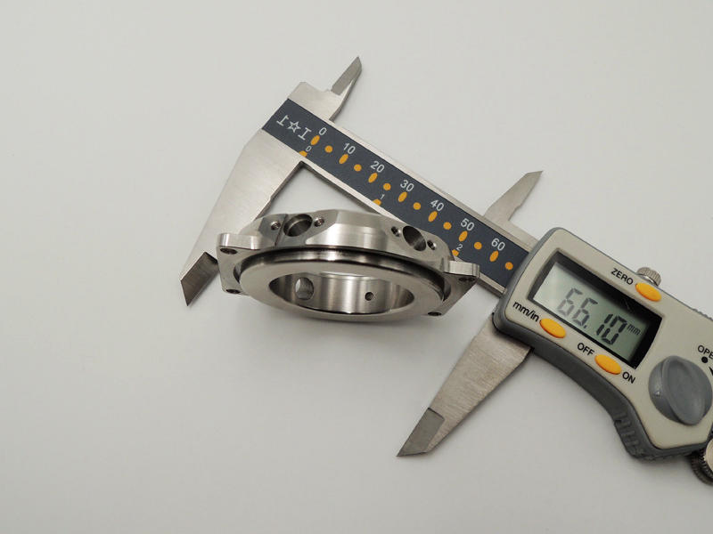
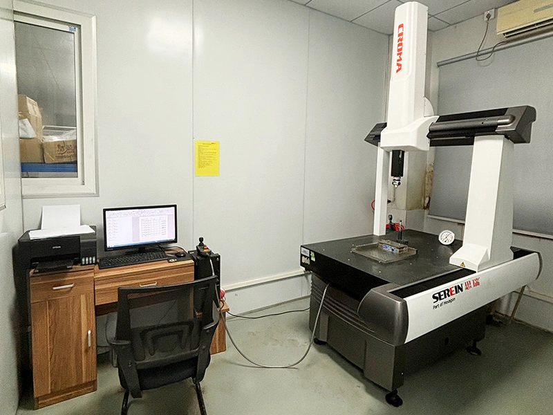
A supplier’s non-destructive contour testing capability should be judged by method selection, calibration control, fixture planning, data review, and release discipline, not by a broad claim about equipment ownership. Blue light scanners, laser scanners, CMMs, CT systems, portable arms, laser trackers, and on-machine probes each have different strengths. Optical scanning can cover freeform surfaces quickly. CMM inspection can certify selected datum-controlled features. CT can inspect internal geometry when the material and size allow reliable reconstruction. On-machine probing can control process drift before unclamping. The right plan may combine methods when one result cannot answer every risk. A supplier should explain why each method is selected, which features each method governs, and how conflicting results are resolved. The buyer should also ask whether calibration covers the actual measurement volume, not only a small reference condition.
Quality assurance should connect inspection to the full production route: machining setup, fixture location, deburring, surface finishing, cleaning, inspection, reporting, and final release. Calibration certificates, uncertainty statements, gage repeatability studies, reference artifacts, and customer-specific report templates should be requested when they affect the buyer’s decision. ISO/IEC 17025 may be relevant for accredited calibration or laboratory requirements, but it should not be claimed as a finished-part guarantee unless the actual scope supports the work. The final decision is simple: use non-destructive contour testing when it answers a functional geometry question more safely than destructive sectioning, and require a report that states method, condition, limitation, and acceptance authority. If the supplier cannot explain uncertainty, alignment, surface preparation, and release hierarchy, the buyer should pause approval until the inspection plan is clarified. For production transfer, the buyer should also ask how inspection feedback returns to machining, fixturing, deburring, and finishing. A measurement system that finds error but does not close the process loop has limited manufacturing value. Quality data must drive corrective action.
Frequently Asked Questions
What are the differences between blue light scanning and CMM in contour inspection?
What is the maximum accuracy achievable with non-destructive contour testing?
Is special treatment required when inspecting transparent or reflective materials?
How can full-size contour inspection be performed on large workpieces?
How long does it take from scanning to obtaining the final inspection report?