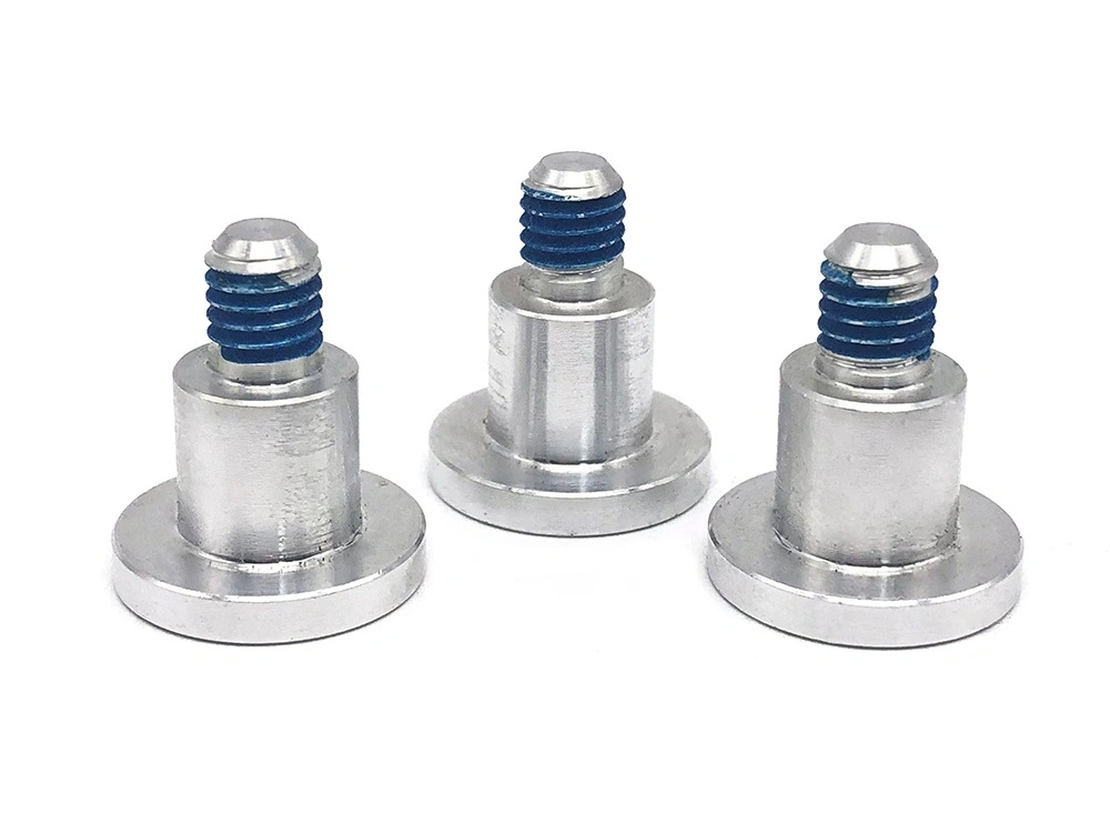
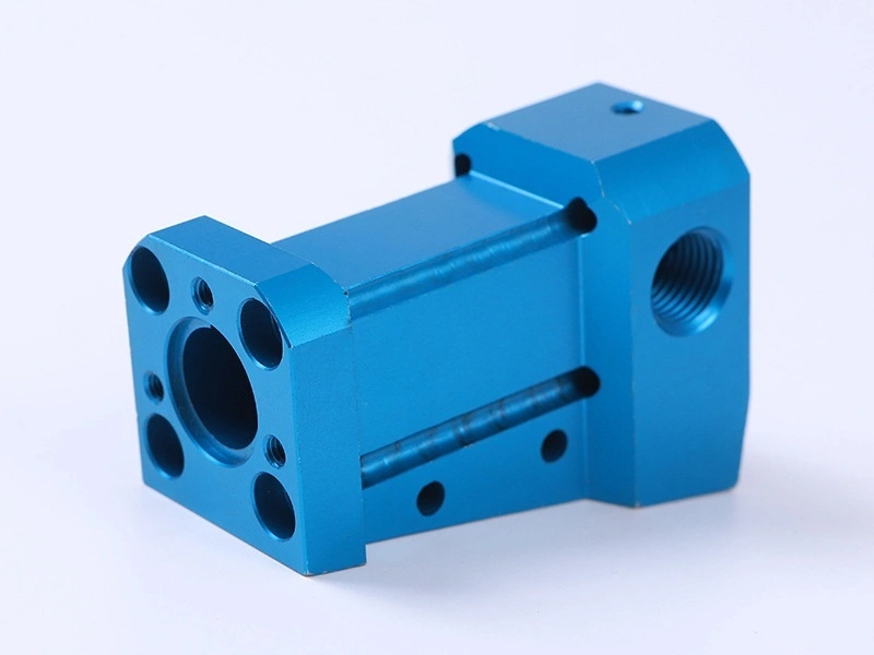
CNC Machined Parts Surface Finishes: From Basic Smoothing to Specialty Coatings
Introduction
Select CNC-machined surface finishes by the function of each surface. Keep a surface as-machined when geometry is sufficient, deburr or tumble when edge condition controls handling, and blast or polish when texture matters. Use anodizing, plating, PVD, or thermal spray only when the material and failure mode support the process. No finish is universally best. Material grade and condition, geometry, datum scheme, tolerance state, surface lay, mating parts, environment, inspection method, maintenance, and cost all change the decision. A finish can reduce corrosion, wear, friction, cleaning effort, heat flux, or cosmetic variation, but it can also create scrap if coating enters a bore, polishing changes a sealing edge, blasting rounds a datum, or an attractive coating hides the wrong base-material choice.
This guide compares as-machined finishes through advanced thermal coatings as an RFQ and manufacturing decision tool. Use it to identify functional and cosmetic faces, choose the correct sequence, define pre- and post-finish dimensions, and request evidence that matches the actual failure risk. It is an overview of selection logic, not a replacement for the material, coating, inspection, or industry specification named on the drawing.
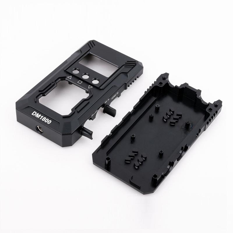
Basic Surface Finishes for CNC Machined Parts
Basic CNC surface finishes control handling safety, burrs, edge condition, visual texture, surface lay, and first-level functional acceptance after machining. These steps are not interchangeable. Deburring targets discrete burrs, tumbling affects the whole exposed part, blasting changes texture and profile, and polishing removes surface peaks. Buyers should state whether a dimension, roughness requirement, or cosmetic criterion applies as-machined, after deburring, after texture preparation, or after the final coating. That inspection state determines machining allowance, datum use, masking, and the supplier route.
1. As-Machined Finish
The as-machined finish is the surface left by milling, turning, drilling, boring, or another cutting operation before secondary finishing. It retains tool paths whose size, direction, and spacing depend on material, tool geometry, feed, speed, runout, coolant, tool wear, feature access, and machine condition. As-machined is often the lowest-risk choice when geometry and fit control function and when later material removal or coating would add no useful performance. If roughness matters, the drawing should state the required parameter, measured surface and direction, and the applicable filtering or evaluation conditions; Ra alone does not describe lay, waviness, isolated scratches, or feed marks.
This finish suits internal mechanical faces, fixture surfaces, electrical contact areas, and non-cosmetic parts where extra finishing would add cost or disturb dimensions. Many internal industrial components should keep selected surfaces as-machined because polishing, blasting, or coating could change conductivity, flatness, contact pressure, or fit. The RFQ should mark acceptable tool marks, prohibited defects, measurement locations, and any face that must remain free of secondary processing.
2. Deburring and Tumbling
Tumbling removes loose burrs and softens exposed edges by moving parts with abrasive or polishing media in a vibratory or barrel process. It can improve handling safety and produce a more uniform edge condition on many small metal or plastic parts. The process is not selective: media shape, compound, cycle, load, part-to-part contact, material hardness, and part mass influence every accessible edge. Thin tabs, fine threads, clips, knife edges, small slots, sealing lands, and engraved details may round or trap media. Cleaning and media-retention checks belong in the route when internal passages or blind features are present.
Tumbling is useful for repeat batches when all exposed geometry can tolerate a controlled edge break and part-to-part contact. Manual or robotic local deburring may be safer for precision bores, datums, optical edges, thin walls, cosmetic corners, and features that cannot accept uniform rounding. The buyer should define maximum edge break, protected features, residual-media acceptance, and whether a sample or first article establishes the approved edge condition.
3. Bead Blasting and Sandblasting
Sandblasting and bead blasting use accelerated media to clean, texture, or profile a CNC surface. Bead blasting generally uses rounder media for a satin cosmetic texture and less aggressive cutting. Sandblasting commonly refers to a more angular or aggressive abrasive route used for scale removal or coating preparation. The practical result depends on media material, hardness, particle shape and size, pressure, angle, stand-off distance, dwell, substrate hardness, wall stiffness, and edge sensitivity. The finish name alone does not define texture, cleanliness, coating profile, or fatigue effect.
Typical applications include:
Pre-treatment before coating or anodizing when profile, cleanliness, and mask boundaries are defined
Visual texture on housings, brackets, covers, and exposed mechanical parts with an approved comparator
Grip texture on handheld components when the profile does not compromise cleanability, fit, or thin-wall stability
A cosmetic blast comparator does not qualify a coating anchor profile. When adhesion is functional, specify media, target surface profile, cleanliness, measurement method, and the coating supplier's preparation requirement. For all blasting, mark threads, precision bores, sealing faces, datums, thin walls, and no-blast zones, then inspect dimensions and visual uniformity after the actual production-intent cycle.
4. Polishing
CNC polishing smooths surface peaks through manual, mechanical, robotic, chemical, or electrochemical material removal. It can improve appearance, cleanability, sliding response, sealing contact, or optical behavior when the selected process reaches the feature uniformly. Material removal matters near small radii, bearing surfaces, sealing lands, logos, threads, cosmetic edges, and reflected-light transitions. Visible grain direction, gloss, blend limits, fixture contact, and acceptable edge change should be approved before production.
Mechanical polishing can reduce roughness on accessible surfaces, but the drawing and approved sample must define the target and permitted geometry change
Electropolishing on suitable stainless steel removes microscopic peaks and may support cleanability and corrosion performance when chemistry, material, removal allowance, and acceptance evidence are specified
Applications include medical-grade surgical components, optical fixtures, sanitary hardware, sealing parts, and visible consumer products. The RFQ should define a comparator or roughness requirement, measurement surface, lay direction, protected features, and whether polishing may alter edge breaks, laser marks, or engraved details.
Functional Surface Coatings and Treatments
Functional CNC coatings and treatments are used when the substrate alone cannot meet corrosion, wear, friction, heat, chemical, electrical, cleanability, or appearance requirements. They add variables that basic smoothing does not: pretreatment chemistry, coating growth or removal, masking, rack contact, cure temperature, porosity, edge coverage, bath or chamber loading, and final inspection state. Define the service environment and controlling failure mode before naming a coating. A marine fastener, sliding guide, electronics enclosure, food-contact component, and hot-gas flange need different material-and-finish systems even when each drawing says "protective coating."
5. Anodizing (Type I, II, III)
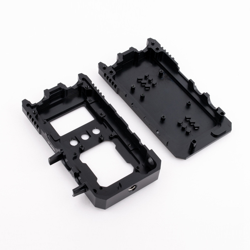
Anodizing forms a controlled aluminum oxide layer electrochemically. Depending on alloy, type, thickness, sealing, and service, it can support corrosion resistance, wear, electrical isolation, color, or surface hardness. Anodizing is not only a color selection. Oxide forms partly below the original surface and partly outward, so external dimensions can increase while bores and thread clearances can decrease. MIL-PRF-8625 is one specification used to classify anodic coating types and classes for aluminum; the drawing must still identify the required type, class, thickness when applicable, sealing, mask boundaries, and acceptance evidence.
Type I (Chromic Acid): A thinner anodic route used on selected aluminum parts when the applicable specification and dimensional requirements support it
Type II (Sulfuric Acid): A decorative or protective route that may support dye, with alloy, color, thickness, sealing, and comparator defined
Type III (Hard Anodizing): A thicker wear-focused route that usually requires more dimensional planning, masking, and finished-state verification
Anodizing is used on brackets, electronics enclosures, fixtures, covers, and structural aluminum parts when alloy and finish requirements are compatible. A precision bore, dowel hole, thread, seal land, and electrical ground pad may need different mask or allowance decisions on the same part. The first article should verify dimensions, thread gauges, sealing, appearance, electrical continuity where required, and datum relationships after the complete anodizing and sealing route.
6. Electroplating (Nickel, Chrome, Zinc)
Electroplating deposits a metal layer to support corrosion resistance, wear, conductivity, solderability, appearance, or dimensional restoration. Performance depends on substrate, pretreatment, undercoat, chemistry, thickness distribution, porosity, rack contact, edge current density, and service exposure. On high-strength steels, applicable specifications may require hydrogen-embrittlement prevention and relief controls. Plating also changes threads, bores, outside dimensions, and surface texture; it cannot correct a wrong alloy, contaminated substrate, or unsuitable joint design.
Nickel plating may support corrosion, wear, solderability, diffusion control, or appearance when the nickel system, undercoat, thickness, porosity, and service environment are defined
Chrome plating may support wear, hardness, low-friction behavior, rebuild, or reflective appearance on selected substrates, often with post-plate grinding for critical geometry
Zinc plating may provide sacrificial corrosion protection for compatible steel hardware when coating system, passivation, thickness, and exposure are suitable
Electroplated components include connectors, shafts, hydraulic parts, fixtures, fasteners, and visible hardware. The RFQ should define plated and no-plate areas, minimum and maximum local thickness, thread allowance, rack-mark zones, post-treatment, hydrogen controls when applicable, appearance limits, and finished-state inspection for electrical contact, wear, fit, or corrosion.
7. PVD Coating (Physical Vapor Deposition)
PVD coating deposits a thin metallic, nitride, carbide, or carbon-based film in a vacuum process. Selected films can increase surface hardness, reduce friction, resist wear, or create a controlled color on compatible substrates. Titanium nitride, zirconium nitride, and diamond-like carbon are different film families, not equivalent grades. Adhesion and life depend on substrate hardness, heat treatment, surface cleanliness, roughness, chamber temperature, geometry, edge support, film architecture, and contact load. A thin PVD film follows rather than hides deep tool marks and substrate defects.
Film thickness must be specified for the chosen PVD system; even a thin film can affect sharp edges, small clearances, and mask transitions
Hardness must be tied to the film, test method, substrate support, and required wear mechanism rather than used as a universal PVD value
Color and sheen depend on film chemistry, base texture, chamber loading, thickness, and the approved visual comparator
PVD may suit tools, wear plates, sliding components, visible hardware, and selected medical-adjacent instruments where a thin film and line-of-sight deposition are acceptable. Buyers should define film system, substrate and heat-treatment condition, mask zones, pretreatment, target thickness, color tolerance, wear or friction test, cleaning method, and whether the base surface is polished, ground, or blasted.
8. Thermal Spraying and Cerakote
Thermal spray coatings, including plasma, arc, and flame-spray routes, deposit heated particles to build a functional layer. A complete system may include substrate preparation, bond coat, top coat, sealing, and post-coat grinding. It may address heat flux, oxidation, wear, erosion, friction, corrosion, or dimensional rebuild when coating and substrate are compatible. Cerakote refers to multiple ceramic-polymer products with different cure and service limits; the trade name alone does not establish temperature, chemical, wear, or marine performance.
Specify continuous and peak substrate temperature, thermal-cycle profile, atmosphere, coating system, bond coat, thickness, mask zones, and permitted post-machining
Validate the governing failure mode through applicable thickness, adhesion or cohesion, hardness, microstructure, corrosion, wear, or thermal-cycle evidence
Selecting the Right Surface Finish: Technical and Economic Considerations
Finish selection changes machining allowance, inspection timing, fixture planning, vendor routing, rework, packaging, and total cost. Start with the function of each surface, then compare compatible processes by failure prevented and process risk. Consider a heat-treated 17-4PH hydraulic valve spool with a hard-chrome wear diameter, unplated threads, and a precision sealing land. A viable route reserves plating and grinding allowance, masks the threads and seal transition, deposits chrome oversize, grinds the coated diameter to final size, and inspects coating thickness, surface condition, runout, thread fit, and the completed assembly. The applicable specification must also define pretreatment and hydrogen controls for the material condition. If the finish map or inspection state is missing, each operation can pass alone while the valve still leaks or binds. A production-intent first article turns the proposed route into evidence before the lot is released.
Key Selection Criteria:
Material Compatibility: Match the exact substrate grade, condition, heat treatment, weld state, and surface preparation to the finish. Anodizing is mainly an aluminum process, passivation applies to suitable stainless chemistry, plating needs a qualified pretreatment, and PVD needs substrate support and temperature compatibility.
Dimensional Impact: Anodizing, plating, powder coating, and thermal spray can change outside dimensions, bores, threads, and mask transitions, while polishing and electropolishing remove material. Define which dimensions apply before finishing and which are accepted after the full route.
Functional Requirement:
Friction or wear control -> Select polishing, hardening, PVD, plating, or overlay only after defining substrate, load, lubrication, motion, and validation test
Corrosion control -> Match material and finish to environment, crevices, galvanic pairs, coating damage, sealing, maintenance, and acceptance evidence
Cosmetic control -> Use blasting, polishing, plating, anodizing, paint, or lacquer with a physical comparator, viewing condition, defect limits, and lot consistency requirement
Heat control -> Select thermal spray, diffusion, ceramic, metallic, or other systems from substrate temperature, heat flux, atmosphere, cycling, and post-heat inspection
Cost vs Performance Trade-off: Include external-vendor routing, masking, coupons, first articles, inspection, rejects, rework, packaging, and approval lead time. Compare total finish cost with the field, assembly, warranty, cleaning, wear, corrosion, or cosmetic failure it is intended to prevent.
Industry Applications by Finish Type
Industry | Candidate Finishes | Decision and Validation Focus |
|---|---|---|
Medical | Electropolishing, passivation, selected PVD | Material compatibility, cleanability, corrosion, residue, surface condition, and documented validation; a finish name alone does not establish sterility or biocompatibility |
Aerospace | Anodizing, plating, PVD, thermal spray | Drawing-controlled material and process, fatigue-sensitive areas, corrosion, wear, heat, masking, coating evidence, and approved suppliers when required |
Consumer Electronics | Blasting, polishing, anodizing, PVD | Texture and color comparator, scratch and wear exposure, grounding zones, logo and edge definition, assembly fit, and lot-to-lot appearance |
Automotive | Plating, paint, powder coating, PTFE systems | Corrosion zone, sliding or release function, temperature, stone impact, appearance, electrical contact, thread fit, and production inspection |
Defense | Ceramic-polymer coating, anodizing, PVD | Exact product grade, abrasion, corrosion, friction, color, chemical exposure, repair, and evidence for the specified service condition |
Surface Finish Performance Comparison Table
Finish Type | Surface and Dimensional Effect | Corrosion Boundary | Wear Boundary | Appearance Boundary | Primary Cost Drivers |
|---|---|---|---|---|---|
As-Machined | Preserves cut geometry; roughness and lay remain process- and feature-specific | Controlled mainly by base alloy, environment, crevices, contamination, and maintenance | Controlled by alloy, hardness, load, lubrication, texture, and mating surface | Tool paths remain visible; suitable when cosmetic uniformity is not required | No secondary finish, but tight roughness or appearance limits can add machining and inspection cost |
Tumbling | Rounds exposed edges and changes texture according to media, cycle, load, and material | Not a corrosion barrier; cleaning and later coating determine protection | Improves burr and edge condition but does not create a hard wear layer | More uniform than raw machining, with part-to-part and media effects to control | Batch size, cycle, media, cleaning, feature protection, and residual-media inspection |
Bead Blasting | Creates a media-defined texture and may round edges or move thin walls | Not a barrier by itself; substrate and subsequent finish control corrosion | Provides texture or preparation, not a hard wear coating | Produces matte texture when media, process window, mask, and comparator are controlled | Media control, masking, cleaning, appearance sampling, profile measurement, and rejects |
Polishing | Removes surface peaks and can change edges, local dimensions, lay, and reflected appearance | May support cleanability but needs suitable material and any required passivation or coating | May reduce friction under defined contacts; it does not add substrate hardness | Gloss or directional grain depends on access, sequence, fixture, and comparator | Labor or automation, access, edge protection, blend limits, inspection, and cosmetic rejection |
Anodizing | Changes aluminum dimensions and texture according to type, thickness, alloy, and sealing | Can support aluminum corrosion protection when coating, sealing, damage, and exposure are defined | Hardcoat may support selected wear modes but can crack or abrade under unsuitable contact | Color and texture vary with alloy, lot, pretreatment, thickness, dye, and seal | Masking, allowance, sealing, color approval, racks, first article, and final inspection |
Electroplating | Adds a deposited layer whose distribution follows geometry, current density, and process control | Depends on plating system, undercoat, thickness, porosity, damage, and exposure | Selected nickel or chrome systems can support wear when load, lubrication, and finish are qualified | Reflectivity and color depend on base polish, undercoat, thickness, chemistry, and defects | Pretreatment, thickness, masking, racks, post-treatment, hydrogen controls, grinding, and inspection |
PVD | Thin film follows the base texture and can affect edges, clearances, and mask transitions | Film-specific; pores, edges, substrate, damage, and environment limit barrier performance | Can be strong for a defined film, substrate, contact, load, lubrication, and wear test | Color and sheen depend on film chemistry, base finish, geometry, and chamber loading | Vacuum route, cleaning, substrate preparation, masking, chamber loading, and qualification |
Thermal Spray | Builds a thicker layer that may require seal, machining, or grinding after deposition | Coating-, porosity-, seal-, substrate-, atmosphere-, and damage-specific | Can support severe wear when feedstock, bond, microstructure, finish, and load are matched | Usually functional unless post-finish and appearance criteria are specifically controlled | Preparation, masking, bond coat, deposition, thickness, seal, post-machining, coupons, and validation |
Conclusion
CNC-machined parts can use simple edge finishing, controlled texture, corrosion treatments, wear films, thermal systems, or multiple finish zones. The correct choice begins with the function and failure mode of each surface. Protect fits and datums through allowance, masking, and finished-state inspection. Protect against corrosion by defining material, environment, crevices, mating metals, coating damage, sealing, and maintenance. Protect against wear or heat by defining contact, load, lubrication, substrate condition, temperature, atmosphere, cycling, and validation.
Supplier workflow matters as much as the finish name. The machinist must reserve the correct allowance and protect datums; the finishing supplier must confirm pretreatment, mask and rack zones, process window, thickness, and permitted rework; quality must measure the completed state and verify assembly or functional evidence. Whether using hard anodizing on an aluminum housing or chrome plating to high-polish automotive trim, release the route from a production-intent coupon or first article when material, geometry, finish stack, or acceptance criteria are new.
For CNC machining services paired with finishing, send the CAD model, revision-controlled drawing, exact material and condition, quantity, finish specification, and process order. Add critical pre- and post-finish dimensions, roughness or profile method, cosmetic comparator, mask map, no-coat zones, operating environment, mating parts, permitted touch-up, and inspection records. A complete RFQ lets the supplier distinguish required finishing from avoidable cost and prevents machined-pass/finished-fail errors.
FAQ
What’s the difference between bead blasting and sandblasting in CNC finishing?
Does anodizing affect part dimensions in precision CNC components?
Which surface treatment offers the best corrosion resistance for marine use?
Can I combine multiple finishes on a single CNC-machined part?
What’s the best finish for high-temperature CNC-machined parts?