How does 3 Axis CNC Milling differ from 4 Axis or 5 Axis Milling?
How Does 3 Axis CNC Milling Differ from 4 Axis or 5 Axis Milling?
Overview of Axis Configurations
The practical difference between 3-axis, 4-axis, and 5-axis CNC milling is controlled rotary motion and the tool access it creates, not an automatic quality ranking. A common three-axis milling configuration controls X, Y, and Z linear motion while the tool-axis direction stays fixed in machine coordinates for each setup. On a common four-axis mill, one rotary axis supplements the three linear axes; indexed machining sets and holds an angular position for the following cut, while simultaneous machining interpolates rotary and linear motion during cutting. On a common five-axis mill, two rotary axes supplement the three linear axes. In 3+2 positional machining, the rotary axes set a fixed cutting orientation; in simultaneous five-axis machining, rotary and linear motion coordinate while the tool direction changes along the path. These labels describe common configurations, not every machine architecture or the axes active in every programmed operation. ISO 841 provides coordinate and motion nomenclature, but it does not prove that a particular machine, mode, tolerance, or result is available. Machine architecture determines whether the tool, workpiece, or both rotate. Before quoting, confirm the installed axes, the programmed mode, and which axes move during each critical operation. Select the least complex route that provides tool and holder access, fixture clearance, controlled datum relationships, and a practical inspection plan.
Capabilities Comparison
Decision Factor | 3 Axis CNC Milling | 4 Axis CNC Milling | 5 Axis CNC Milling |
|---|---|---|---|
Motion Mode | Common three-axis configuration: linear X, Y, and Z; the tool-axis direction stays fixed in machine coordinates during each cutting setup | Common four-axis configuration: three linear axes plus one rotary axis; indexed mode holds its angle during a cut, while simultaneous mode interpolates rotation with linear travel | Common five-axis configuration: three linear axes plus two rotary axes; 3+2 fixes an orientation for a cut, while simultaneous mode changes orientation during the path |
Tool Access | Suitable when the cutter and holder can reach every feature from planned fixed directions with practical tool length | Adds angular access around one rotary axis, subject to rotary travel, fixture position, holder clearance, and machine envelope | Adds compound orientations, but access still stops at rotary limits, fixture interference, holder collision, or excessive tool reach |
Geometry Fit | Prismatic features, pockets, bosses, faces, and hole patterns reachable from stable setup orientations | Separated angular faces, radial features, or wrapped paths that can use one controlled rotary degree of freedom | Compound angles, deep cavities, or contoured paths that need two rotary degrees of freedom for access or tool orientation |
Setup Time | Programming and fixtures can be simpler when access and workholding are straightforward, but several tool directions may require re-clamping and renewed datum control | Indexing can retain one clamping through several angles; rotary zero, centering, support, and clearance still need verification | May retain one clamping for more orientations; CAM, postprocessing, simulation, prove-out, and inspection planning add preparation |
Accuracy & Efficiency | Efficient when access is open and critical relationships do not depend on uncontrolled datum transfer between setups | Can remove some re-clamps, but rotary positioning, fixture alignment, tool reach, and inspection still govern the result | Can shorten tools or reduce handling on suitable geometry; axis count alone proves neither tolerance, finish, nor cycle time |
Use Case Examples
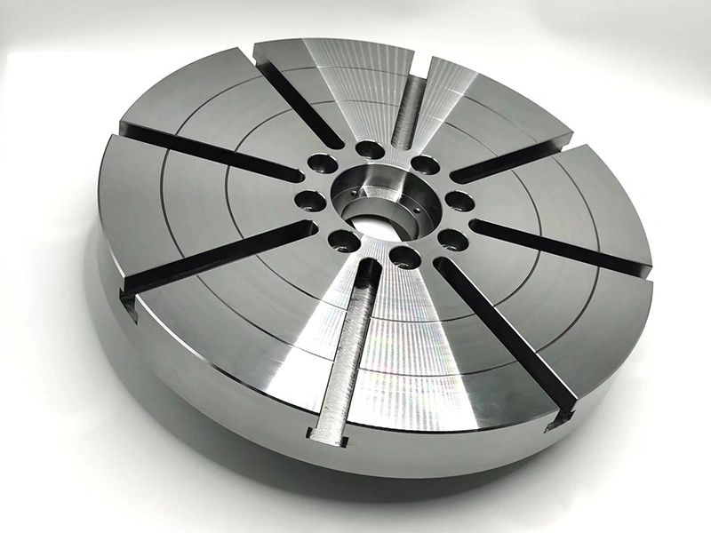
3 Axis CNC Milling is a strong candidate for plates, brackets, enclosures, and aluminum housings when the required cut surfaces face planned fixed tool directions. The linked page is specifically an Aluminum 6061 material reference; it does not determine the axis route for a housing. For an open-top electronics enclosure, map the gasket land, standoffs, and vertical threaded holes to the Z direction, then check cutter reach and holder clearance against the CAD model. A connector opening on a sidewall, an undercut, or an angled face does not by itself rule out 3-axis milling. Change the access plan when the cutter or holder cannot reach the feature from a fixed direction, or when the reachable option cannot meet clearance, stiffness, chip-control, support, or acceptance requirements. Alternatives include another setup, a suitable form tool, indexed rotary positioning, another process, or a design change. Approve 3-axis only when the setup and tooling map reaches every specified feature without impractical tool extension or fixture collision.
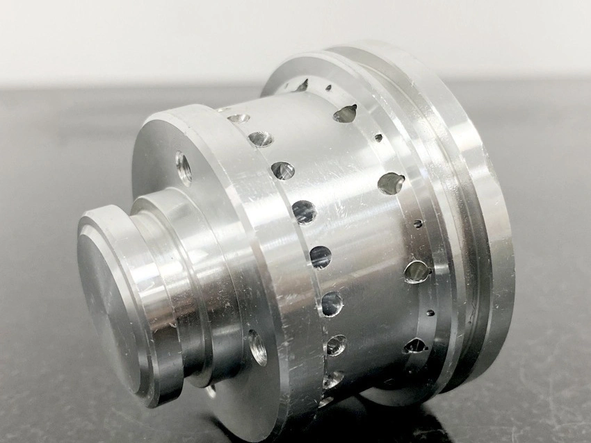
4 Axis CNC Milling is useful in the common three-linear-plus-one-rotary configuration when one controlled rotary degree of freedom can replace repeated manual positioning or support a coordinated wrapped path. A process review for gear housings or impellers should not select 4-axis machining from the part name alone; the link leads to the broader Multi-Axis Machining service. For indexed work, identify each required angle and confirm that the rotary axis remains stationary during its cut. For simultaneous work, identify the feature that needs coordinated rotary motion. In both cases, verify rotary travel, cutter and holder clearance, fixture support, datum strategy, and inspection access.
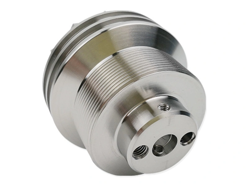
5 Axis CNC Milling is justified in the common three-linear-plus-two-rotary configuration when two controlled rotary degrees of freedom solve an access or tool-orientation problem that 3-axis or 4-axis routes cannot handle efficiently. For complex mold cores, the route review should distinguish discrete angled cuts suited to 3+2 from surfaces that require the tool direction to change during cutting. Deep cavities and angled walls may permit a shorter tool, but hidden geometry can remain inaccessible because of spindle size, holder shape, fixture obstruction, rotary limits, or collision clearance. Simultaneous motion also requires a suitable machine configuration, control function, postprocessor, verified simulation, and part-specific inspection.
Technical Advantages of Higher Axes
Surface Finish: Changing tool orientation can permit a shorter, stiffer tool or a more suitable cutter contact on a contoured surface. That can reduce one source of deflection or contact variation, but it does not guarantee the drawing's texture requirement. Cutter geometry, material, toolpath transitions, engagement, rigidity, tool condition, and measurement method still apply. For an open planar face, a rigid 3-axis route may carry less process risk.
Precision: Keeping related features in one clamping can reduce the number of datum transfers, yet the benefit exists only when rotary positioning, fixture alignment, thermal state, tool deflection, and probing or inspection are controlled. When a geometric requirement references datums, evaluate it from the applicable drawing datum reference frame using the stated acceptance method. Compare the proposed setup map with the critical feature relationships, and do not use axis count or a machine-axis test as a finished-part tolerance claim.
Cycle Time: Rotary access can reduce handling, fixture changes, and repeated work-offset setting. It can also add CAM programming, postprocessor validation, collision simulation, prove-out, machine setup, and first-piece inspection. Compare total process time and risk for the required quantity, including preparation and inspection, rather than spindle time or setup count alone. A simpler route may be the better production decision when geometry is accessible.
Advanced Milling Services for All Axis Requirements
Use the 3 Axis CNC Milling, 4 Axis Milling, and 5 Axis High-Precision Milling references to compare motion and access, then make the RFQ decision from the controlled CAD model and drawing. Supply material and condition, quantity, functional datums, critical dimensions and geometric controls, surface requirements, inaccessible directions, and required inspection records. For a Multi-Axis Machining review, ask the supplier to return the proposed mode, setup orientations, rotary and tool-access limits, fixture concept, datum-transfer plan, collision-control method, and inspection approach. For each critical operation, confirm whether the quoted rotary axes index and remain fixed or are commanded to move during cutting, and whether the required control and postprocessor functions are available for that route. Choose the least complex process that reaches the geometry, preserves the drawing relationships, and supports a credible acceptance plan.