Ultrasonic Testing Solutions for Internal Defects in CNC Machined Parts
Introduction: Why Do CNC-Machined Parts Require Internal Defect Inspection?
CNC-machined parts require internal defect inspection when hidden cracks, pores, inclusions, lack of fusion or heat-treatment discontinuities could affect strength, sealing, fatigue life or safety after machining. Visual inspection and dimensional inspection can confirm shape, surface and tolerance, but they cannot prove that the internal material is free from rejectable indications. CNC-machined parts made from forged, cast, welded, additively manufactured or heat-treated stock may carry internal risks that remain invisible after milling, turning or grinding. This is most important for load paths, pressure boundaries, rotating parts, sealing lands, critical holes and features exposed to cyclic stress. The need also increases when a part cannot be destructively sectioned after machining. Buyers should decide which internal defects matter for the application, which NDT method can detect them, and what acceptance criteria should appear in the RFQ.
Ultrasonic testing is often selected because sound waves can travel through the part and return echoes from internal boundaries. The method is useful for thick metallic sections, selected forgings, billet-derived components, welded or additive features, and parts where radiography, magnetic particle inspection or dye penetrant inspection cannot answer the main risk. UT is not a universal health check. It has limits near surfaces, around complex geometry, in coarse-grained materials, and when the defect is poorly oriented to the sound beam. A reliable UT plan therefore starts with material, stock form, defect type, section thickness, probe access, surface condition, applicable standard and buyer reporting requirements. The buyer should also state whether the defect risk comes from raw material, welding, additive build, heat treatment, rough machining or service damage. Each source changes the expected location and orientation of the indication.
Ultrasonic Testing (UT) Technology Explained: Principles and Advantages
How Does Ultrasonic Testing Work?
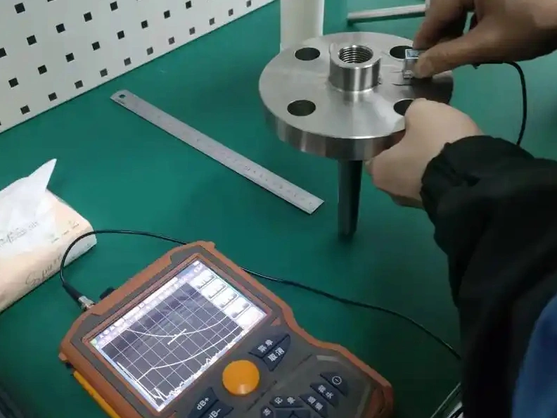
Ultrasonic testing sends high-frequency sound into a component through a probe and couplant. When the sound reaches a boundary, a pore, a crack face, an inclusion or the back wall, part of the energy reflects to the probe. The instrument displays the return signal as amplitude, depth and time-of-flight information. The inspector compares those signals with reference sensitivity, scan coverage and the acceptance rule. A small echo is not automatically a rejectable defect, and a quiet screen is not proof that every smaller indication is absent. The inspection result depends on calibration, material noise, beam angle, defect orientation, surface condition and reporting threshold. Reference blocks or known reflectors are needed because the screen response must be tied to a repeatable sensitivity, not only to operator judgment.
For buyer decisions, UT should be described as a controlled measurement method, not as a black-box quality promise. The report should state probe frequency, inspection mode, reference block, scan path, material thickness, rejected zones, detectable volume and whether the result is pulse-echo, angle-beam, phased-array or immersion C-scan. UT is most useful when the inspection stage is tied to raw material verification, intermediate machining, heat treatment or final acceptance. The RFQ should also ask whether the UT result is for process screening, final release, or customer compliance documentation. This distinction matters because a screening scan may guide process development, while a release scan must satisfy the purchase order and acceptance standard. It also helps purchasing compare quotes, because a supplier offering only a simple shop-floor scan is not quoting the same risk control as a supplier offering documented final acceptance.
What Are the Unique Advantages of UT Compared with X-ray and Magnetic Particle Inspection?
UT can be stronger than X-ray or magnetic particle inspection when the main risk is a planar crack, a thick-section discontinuity or a defect that lies below the surface. Radiography can show volumetric density differences well, but it may miss tight cracks in an unfavorable orientation. Magnetic particle inspection is useful for surface and near-surface defects in ferromagnetic materials, but it cannot inspect nonmagnetic alloys or deep internal zones. Dye penetrant is limited to surface-breaking defects. UT can inspect deeper material volumes, estimate reflector depth and guide further investigation when sectioning is not acceptable. The method is also practical for in-process decisions because a scan can be repeated after rough machining, heat treatment or repair without destroying the part.
The advantage is conditional. A planar crack reflects best when the sound beam strikes the crack face at a useful angle. A rounded pore, an inclusion and a lack-of-fusion indication can return very different signals. UT may also struggle near edges, holes, thin walls, coarse grains or curved surfaces. Buyers should not choose UT only because it is portable or non-destructive. For precision machining services, the better decision compares failure mode, material, geometry, allowable access and acceptance standard. If the defect is surface-breaking, magnetic particle or penetrant testing may be better. If the defect is volumetric porosity in a complex casting, radiography or CT may be needed. When no single method covers the full risk, a supplier should explain the combined inspection route instead of forcing every defect type into UT. That explanation should name what UT will detect, what UT may miss, and what secondary method closes the gap.
Common Types of Internal Defects in CNC Machined Components
Shrinkage Porosity and Looseness
Shrinkage porosity and looseness usually come from casting, solidification, powder metallurgy or additive processes before final machining. CNC cutting can expose the part shape, but machining does not remove every internal void. During superalloy machining, internal porosity can reduce effective load area and create stress concentration in hot or cyclic service. UT can help locate larger clusters or reflectors when the material has suitable acoustic response. The buyer should identify whether the suspected defect is isolated porosity, distributed shrinkage, lack of bond or a density-related indication, because each one affects UT sensitivity differently. A porosity cluster may require different acceptance logic from a single planar crack. If density variation is the main concern, radiography or CT may provide a clearer map.
Internal Cracks and Non-metallic Inclusions
A useful inspection scenario is a finish-machined shaft made from a forged stainless steel or titanium blank. If the highly stressed fillet carries a transverse crack or inclusion risk, one normal-beam scan can miss a planar reflector parallel to the sound path. The inspection plan may need radial and axial access, selected beam angles, and a representative reference reflector. multi-axis machining can expose a pre-existing discontinuity or change the remaining stress distribution, but machining distortion alone is not proof of an internal crack. Inclusion effects also depend on alloy, inclusion type, orientation, and service environment in titanium alloy machining and stainless steel machining. The buyer should identify the critical fillet, expected defect orientation, examination stage, and acceptance rule. Validation then compares scan coverage and sensitivity with the stated risk, rather than treating any detected echo as an automatic rejection.
Lack of Fusion and Porosity
Lack of fusion appears in welded or additively manufactured material when adjacent layers or weld passes do not bond as required. Porosity may also form from trapped gas, powder contamination, poor shielding or process instability. In prototype manufacturing and low-volume production, the inspection plan should separate development learning from final release. A prototype scan may identify where process parameters need correction. A production acceptance scan must define reportable indication size, scan coverage, calibration block, acceptance criteria and reinspection rules after repair or rework. If the part will later be machined from an additive blank, the buyer should decide whether UT happens before machining, after rough machining, after finishing, or at more than one stage.
Neway’s Ultrasonic Testing: Solutions and Service Process
Step One: Pre-inspection Consultation and Customized Plan
A practical UT workflow starts by reviewing the drawing, material certificate, manufacturing route, service risk, and customer acceptance requirement. The supplier should identify likely defect types, defect orientation, examination volume, critical surfaces, access limits, and the applicable standard before quoting. ISO 16810 defines general principles for industrial ultrasonic testing, while ISO 16811 addresses sensitivity and range setting. Neither document supplies a universal part acceptance limit. The product standard, drawing, purchase order, or approved procedure must provide that decision rule. This distinction prevents a common RFQ mistake: requesting ultrasonic testing without defining the defect or rejection basis. The proposed scan plan should name probe type, frequency, coupling method, reference block, report format, and zones with reduced sensitivity. Parts with multiple stock forms or welded regions need separate examination conditions. The plan should also identify who reviews relevant indications and when buyer approval is required for disposition.
Step Two: Surface Preparation and Coupling
Surface preparation controls how consistently sound enters the part. Roughness, scale, dirt, sharp curvature, and loose coating can cause coupling loss or geometric echoes that compete with defect signals. The acceptable surface condition depends on probe footprint, frequency, couplant, geometry, and required sensitivity; a single roughness limit is not valid for every UT procedure. The inspection plan should define whether machining, grinding, cleaning, coating removal, or local access pads are required before scanning. A calibration check made through a representative surface helps show whether the selected setup maintains the required response. For finished parts, the buyer should confirm whether couplant residue, water exposure, or temporary coating removal is acceptable. When inspection must occur after coating, the approved procedure must address attenuation and coupling through that coating.
Step Three: Advanced UT Equipment Scanning and Data Acquisition
Scanning should follow a documented path that covers the required volume from accessible surfaces. Conventional pulse-echo UT may suit simple sections. Angle-beam UT or phased-array UT may be needed when expected defects are directional or geometry is complex. ASTM E317 is used to evaluate selected performance characteristics of pulse-echo ultrasonic equipment; it is not a finished-part acceptance standard. Data records should identify gain, time base, probe angle, focal law when applicable, scan index, calibration checks, and excluded zones. Full coverage means coverage of the specified examination volume at the declared sensitivity. It does not mean every microscopic flaw in every orientation is detectable. If a hole, fillet, rib, or curved wall blocks the beam, the report should identify the limitation and any complementary method used to close the gap.
Step Four: Data Analysis and Professional Report Issuance
UT reporting should turn waveform or scan data into a decision that the buyer can review. A useful report identifies the part number, revision, material, thickness, inspection standard, procedure, equipment, probe, calibration reference, operator qualification, scan coverage, indications found, acceptance criteria and final disposition. When an indication is found, the report should separate location, amplitude, estimated size, type, confidence and recommended action. Personnel qualification should be documented by the applicable scheme and scope. It should not be assumed from a marketing claim or from the word certified alone. If the acceptance standard allows engineering review, the report should show whether the lot was accepted, rejected, sorted, repaired or sent for additional testing. The report should also state if any surface, depth zone or feature was excluded.
Applications of Ultrasonic Testing in Critical Industries
Aerospace: Engine Blades and Landing Gear Components
In the aerospace sector, UT may be used for selected forged, wrought, welded or additively manufactured components where internal integrity affects fatigue or fracture risk. Materials such as Inconel 718 can require tight control of grain structure, heat treatment state and scan sensitivity. The buyer should not rely on a generic aerospace label. The RFQ should provide the applicable material specification, customer NDT requirement, acceptance class, part criticality and whether the supplier needs a specific accreditation or customer approval for that UT scope. It should also clarify whether the inspected item is raw stock, a near-net blank, a repaired part or a finished CNC component.
Medical: Implants and Surgical Instruments
For medical device parts, UT suitability depends on part type, material, risk classification, surface condition and validation requirements. A trial instrument, fixture or surgical tool may have a different inspection requirement from an implant. Materials such as Ti-6Al-4V can transmit sound well in some forms, but geometry, surface finish and regulatory documentation still matter. Buyers should specify whether UT is for raw material screening, manufacturing validation, lot release or failure investigation. That distinction changes the standard, sample size and report evidence. If the surface is polished, coated or passivated after UT, the buyer should also define the final inspection state.
Energy: Turbine Rotors and Pressure-Bearing Components
In the power generation and oil and gas sectors, UT may support inspection of pressure-bearing, rotating, welded or high-temperature components. The method can identify internal reflectors before parts enter service, but acceptance normally depends on a code, material specification or project requirement. A valve body, manifold, rotor, shaft or pressure component may need different probe angles and reporting thresholds. Buyers should ask whether ASME, ASTM, ISO, customer specifications or project drawings define the decision rule. The inspection plan should also state whether repair, reinspection or rejection is required after a relevant indication. For pressure-related parts, the report should connect indication disposition to the construction code or purchase specification, not only to an internal supplier note.
Key Advantages of Choosing Neway for Ultrasonic Testing?
The main advantage a buyer should require when choosing Neway for ultrasonic testing is a documented connection between the inspection plan and the manufacturing route, not a list of equipment. For a one-stop manufacturing service, the practical value comes from deciding when to inspect raw stock, when to inspect after rough machining, when to repeat after heat treatment, and when final dimensional inspection should follow UT. The buyer should ask how ultrasonic testing is linked with machining, deburring, heat treatment, surface finishing, dimensional inspection and nonconformance control. The answer should include workflow, not just a certificate name. This is especially important when a defect found after finishing would require expensive rework or when raw material rejection must be separated from machining responsibility.
For heat-treated parts, UT can examine internal discontinuities or cracking only where depth, orientation, material response, and access match the qualified procedure. Surface-breaking quench cracks may require magnetic-particle or penetrant testing instead. For parts that have undergone deburring processes, the supplier should confirm that surface condition still supports coupling and that edge rounding has not removed a critical reference surface. The RFQ should state the inspection stage, finish state, cleaning requirement, and required data retention. If UT occurs before a later machining cut removes material, the buyer should confirm that the remaining critical volume is still represented by the scan.
Material response should drive UT parameters. Conventional stainless steel SUS304, nickel alloy, titanium, aluminum, plastic and ceramic parts can require different probe frequencies, couplants, scan paths and acceptance standards. The best buyer request is specific: provide drawing revision, material grade and condition, manufacturing route, expected defect type, critical section thickness, surface finish, acceptance standard, required report fields and any customer approval requirements. That information lets the supplier return a defensible UT plan instead of a generic promise about internal defect detection. A practical review also separates defect screening from dimensional acceptance. UT can support an integrity decision, but final release still needs the drawing's datums, tolerances and surface requirements checked by the appropriate dimensional or visual method. If the supplier cannot state inspection volume, reportable indication size, calibration method and acceptance criteria, the buyer should treat the UT proposal as incomplete. The next step is to clarify those items before price comparison or production release.
FAQ
How small can internal defects be for ultrasonic testing to detect them?
Is ultrasonic testing applicable to all materials, such as plastics and ceramics?
What are the main differences between X-ray inspection and ultrasonic testing?
Which international standards do Neway’s ultrasonic testing services comply with?