X-ray Inspection Workshop for Internal Defect Detection in CNC Parts
Revealing the Invisible World: Why X-ray Inspection Is Indispensable
X-ray inspection is useful for CNC parts when hidden porosity, shrinkage voids, inclusions, cracks, blocked channels, trapped powder or missing internal features could affect strength, sealing, fatigue life or assembly safety. Visual inspection and dimensional inspection can confirm outside shape, surface finish and tolerance, but they cannot prove that the internal volume is acceptable. The method should be selected when the buyer needs image-based evidence of internal geometry or density variation, especially when destructive sectioning would waste the part. The RFQ should define the material, wall thickness, suspected defect type, critical zones, inspection stage, report format and acceptance rule.
For buyers using precision machining services, X-ray inspection is not a replacement for good process control. It is a verification tool that helps decide whether a high-risk part can move from prototype approval to production release. X-ray inspection is strongest when defect evidence must be visible to design, quality and purchasing teams. It is weaker when the part is too dense, too thick, too large for the scan envelope or controlled by acceptance criteria that require another NDT method. Buyers should ask whether 2D radiography, real-time imaging or industrial CT is the correct level of evidence before approving inspection cost. The decision should also include when to inspect: raw stock, after rough machining, after heat treatment, after finishing or at final release.
The Core of X-ray Testing Technology: From 2D Radiography to 3D Industrial CT
2D Real-time Imaging: Rapid Screening and Positioning
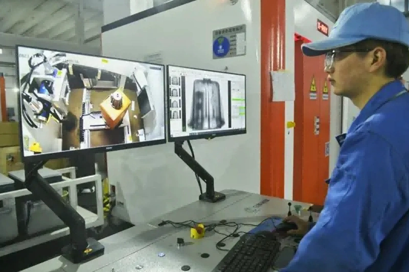
2D X-ray inspection creates a projection image by passing radiation through the part and recording differences in transmitted intensity. Dense regions, thick walls and high-atomic-number materials attenuate more radiation. Voids, pores and missing material transmit more radiation and appear as contrast differences. This makes 2D radiography suitable for quick screening, weld review, assembly verification and preliminary defect location. Its limitation is geometric overlap. A defect can be hidden behind another feature if the view angle is poor. Buyers should define the required view direction, magnification, image sensitivity and rejectable defect type when 2D imaging is used for release. For a production lot, the same view angle and exposure setup should be controlled so that image comparison remains meaningful from part to part.
3D Computed Tomography (CT): Three-dimensional Quantitative Defect Analysis
Industrial CT collects many X-ray projections and reconstructs a 3D voxel volume. CT can show internal passages, wall thickness, porosity distribution, trapped material and geometry that cannot be reached by external measuring tools. CT can also compare scan data with CAD when the scan setup, calibration and surface determination method support the required decision. Voxel size is not the same as dimensional accuracy. Practical accuracy depends on part size, material density, focal spot, detector, reconstruction settings and measurement uncertainty. ASTM E1441 and ISO 15708 provide CT guidance and terminology, while the buyer's drawing or project specification still defines acceptance. CT is most valuable when the report names the inspected volume, the smallest relevant indication and the reason that CT is better than sectioning, borescope inspection or CMM measurement for that feature.
Which CNC Parts Must Receive X-ray Health Checks?
Components with Complex Internal Channels or Cavities
CNC parts with internal channels, cross-drilled holes, manifolds, cooling passages or hidden cavities are strong candidates for X-ray inspection. A part made through multi-axis machining services may look correct outside while an internal passage still contains a burr, chip, broken tool fragment or local wall-thickness error. X-ray inspection can confirm whether the hidden volume is open and whether a foreign object remains. The buyer should mark which internal passages are functional, which surfaces are sealing boundaries and which blocked area would cause rejection. A clear inspection plan avoids paying for images that do not answer the real risk. If the part also requires leak testing, the X-ray result should be connected to the leak path rather than treated as a separate picture.
Lightweight Yet High-Strength Aerospace and Automotive Components
Lightweight parts made by aluminum alloy machining and titanium alloy machining often use thin walls, pockets and optimized load paths. Internal porosity, shrinkage, inclusions or cracks can reduce fatigue life even when the external dimensions pass. X-ray inspection is useful when a casting, forging, additive blank or welded preform is later machined into a critical geometry. The inspection stage matters. Screening raw stock may catch material defects early, while final CT may verify the remaining wall after machining. Buyers should specify whether the concern is material quality, machining damage, final wall thickness or assembly risk. For thin-wall parts, unclamping, residual stress release and later finishing can change the relationship between the scanned feature and the final functional surface.
Safety-Critical Medical Implants and Instruments
For medical device parts, X-ray or CT inspection may support design validation, internal geometry review or selected risk controls. It should not be written as a universal requirement for every medical part. A surgical instrument, fixture, trial component and implant can have different evidence needs. CT may help verify internal channels, porous structures, trapped powder or hidden assembly features. The buyer should define whether the scan supports prototype learning, regulatory documentation, incoming inspection or production release. Acceptance should reference the drawing, material specification and customer quality agreement. If cleanliness, passivation or electropolishing is performed after scanning, the final release plan should state which condition is actually accepted.
Complex Structures Produced by Additive Manufacturing
Parts produced by 3D printing can contain lack of fusion, gas porosity, unmelted powder, thin-wall variation and blocked internal channels. CT is often the most informative method when a lattice, conformal cooling passage or enclosed cavity cannot be inspected with a probe. The buyer should still define detectability limits. Fine pores, dense materials and large build envelopes can reduce contrast or resolution. If the additive part is machined after printing, the scan should match the actual decision point. A pre-machining scan may protect machining time, while a final scan may confirm the delivered geometry. When machining removes part of the printed skin, the remaining critical volume should be identified before the scan plan is approved.
Inside an X-ray Testing Workflow: Equipment Inputs and Process Controls
Introduction to High-Precision X-ray Inspection Systems
An X-ray inspection system is defined by source energy, focal spot, detector resolution, part positioning, shielding, software and calibration control. Higher voltage improves penetration for dense or thick parts, but it can reduce contrast for small low-density defects. A smaller focal spot can improve geometric sharpness, but part size and working distance may limit magnification. Detector pixel pitch, exposure time, filtering and artifact correction also affect the result. Buyers should ask for the planned scan envelope, maximum material thickness, expected voxel size, image quality indicator or calibration reference and the reportable indication threshold. These inputs are more useful than a generic equipment description. A credible plan also states whether the part will be fixtured, rotated, scanned in one setup or scanned in multiple regions of interest.
Standardized Five-Step Testing Process
A reliable X-ray workflow starts with sample intake and requirement review. The supplier should confirm drawing revision, material, critical zones, suspected defects, acceptance standard and whether the part can be handled without changing its condition. The second step is method planning, including 2D view angle or CT scan strategy. The third step is parameter selection and calibration. The fourth step is image acquisition and reconstruction when CT is used. The fifth step is interpretation, disposition and report issue. Each step should produce traceable evidence. The report should connect requirements, approved parameters, calibration checks, indications and disposition without gaps. If the inspection supports shipment release, it should also identify who reviewed the indications and how nonconforming findings are escalated.
From Data Acquisition to 3D Model Reconstruction
CT reconstruction turns projection images into a voxel model, but the model is only as reliable as the scan setup. Beam hardening, scatter, movement, insufficient projections and incorrect threshold settings can distort edges or create artifacts. A practical review should compare the CT result with the drawing question. If the buyer needs porosity screening, the report should define pore size threshold, analyzed volume and acceptance rule. If the buyer needs dimensional comparison, the report should state alignment method, datum selection, surface determination and measurement uncertainty. CT data is powerful because it can show hidden evidence, not because it removes the need for acceptance discipline. When CT is used for reverse engineering, the buyer should also separate mesh generation from inspection acceptance.
Accurate Identification: Typical Internal Defect Atlas Under X-ray
Porosity and Shrinkage Voids
In cast aluminum alloy ADC12 components, pores often appear as rounded low-density indications, while shrinkage voids can look irregular, dendritic or sponge-like. The buyer should not judge risk by image appearance alone. Location, size, cluster density, wall thickness and service loading determine whether an indication is acceptable. A pore near a sealing land, thread root, thin wall or fatigue-critical radius can matter more than a larger pore in a noncritical area. The RFQ should define the relevant volume and whether the report needs pore count, maximum pore size, porosity percentage or pass/fail disposition. If the same casting will receive machining allowance removal, the scan should focus on the material that remains after final cutting.
Cracks and Lack of Fusion
For high-temperature alloys such as Inconel 718, cracks, lack of fusion and linear indications need careful view selection. X-ray can show planar defects when orientation and contrast are favorable, but some tight cracks are easier to evaluate with ultrasonic testing, dye penetrant or magnetic particle inspection depending on material and surface access. Lack of fusion in additive or welded stock can reduce load path continuity after machining. Buyers should define whether the inspection must find open cracks, embedded lack of fusion, porosity clusters or heat-treatment-related discontinuities. The selected method should match that defect orientation. If the service load is cyclic, the acceptance rule should consider crack-like shape and location, not only projected length.
Inclusions and Density Variations
Foreign particles, non-metallic inclusions and density variations can appear as bright or dark indications depending on how their density differs from the base material. In plastic machining, visible contrast may come from embedded particles, trapped metal chips, voids or mixed material. In metal parts, inclusions may be related to casting, forging, welding or powder feedstock. The report should separate observed indication from engineering disposition. A bright spot in the image is not automatically a reject. The buyer needs size, location, material context and the applicable acceptance rule. If the inclusion is near an electrical, sealing or cosmetic feature, the disposition may differ from a buried nonfunctional region.
Foreign Objects and Missing Parts Inside Assemblies
X-ray inspection can verify internal assembly conditions without disassembly. This is useful for connectors, housings, sensors, manifolds, valves and selected automotive electronic assemblies. The method can identify missing fasteners, misplaced inserts, trapped chips, solder defects, blocked ports or seal position problems. The buyer should provide the expected assembly state and define what deviation is rejectable. When several materials overlap in one view, 2D imaging may be insufficient. CT or multiple 2D angles may be needed to avoid hiding one component behind another. For assemblies with adhesives or elastomers, the inspection plan should also confirm whether material contrast is enough to see the target feature.
Beyond Inspection: Closed-Loop Application of X-ray Data in Design and Manufacturing
Providing Decision Evidence for Design Validation
During the prototyping stage, X-ray and CT data can show whether internal design intent survived manufacturing. For example, a machined aluminum manifold made from a cast blank may pass external dimensions while CT shows a shrinkage void opening into a sealing wall. The team can correlate the indication to CAD and a leak-test path before destructive sectioning. The buyer can then change the blank route, revise machining allowance or add stock screening before production release. An additively manufactured cooling channel may instead need trapped-powder review at a bend. These findings support design validation, but they do not replace complete production qualification. A useful prototype report explains which finding changes the next design or process decision.
Guiding Process Optimization
X-ray data can support process improvement when the defect pattern is linked to a manufacturing step. Cracks after heat treatment may point to stress concentration, quench severity, geometry sensitivity or material condition. Porosity in PEEK or other polymer parts may relate to feedstock, molding history, machining heat or trapped contamination. The buyer should ask the supplier to connect each relevant indication to a likely process cause and a verification action. Useful corrective actions may include stock screening, machining allowance changes, cleaning validation, fixture changes or a revised inspection stage. When the same defect repeats, the response should be a controlled process change, not repeated final sorting only.
Enabling Precise Failure Analysis
When a part fails during testing or service, X-ray inspection can help decide whether the origin is material, machining, assembly, heat treatment, surface condition or misuse. A useful failure analysis scan compares failed areas with intact areas and checks whether the indication aligns with the fracture path or load direction. X-ray results should be combined with fracture surface review, dimensional inspection, material certification and service history. Buyers should avoid using CT images as a single-cause conclusion when the failure mode needs metallography or mechanical testing. The best report states evidence, limits and next verification step. If the failed part cannot be sectioned immediately, CT can preserve an internal evidence record before destructive analysis begins.
How Buyers Should Evaluate an X-ray Testing Workshop
A capable X-ray testing workshop should connect inspection to the part's manufacturing route, not only produce images. The buyer should look for a workflow that starts with drawing review, material understanding, defect-risk planning and report requirements. The supplier should explain why 2D, CT or another NDT method is appropriate for the part. The report should identify inspected volume, scan parameters, acceptance criteria, indications found and disposition. If the same part also needs dimensional release, the supplier should state which dimensions are checked by CT and which still require CMM, optical or functional measurement. This separation prevents an internal defect report from being mistaken for full drawing approval.
For low-volume production, X-ray inspection can help validate a risky feature before production scaling. For larger lots, the inspection plan should define sampling method, reaction plan and whether X-ray is used for launch validation or continuing process control. Buyers should request traceability to drawing revision, material lot, inspection date, operator or reviewer, scan condition and software version when CT data affects release. That evidence is more valuable than a broad statement that the workshop uses advanced equipment or has experienced staff. If report approval will delay delivery, the buyer should define which results are needed before shipment and which can remain engineering records.
The strongest purchasing route is to treat X-ray inspection as one step in a controlled one-stop service workflow. Raw stock selection, machining sequence, cleaning, deburring, heat treatment, surface finishing, dimensional inspection and final reporting should be coordinated around the part risk. If a defect would be expensive to find after finishing, specify the inspection earlier. If a final internal channel must be clear after all operations, specify the final scan state. The next step is to send the drawing, CAD model, material, process route, suspected defects, critical zones and acceptance standard with the RFQ. That package lets the supplier return a method-specific plan rather than a generic X-ray quote.
Frequently Asked Questions (FAQ)
What are the main differences between X-ray inspection and ultrasonic testing?
What level of accuracy and resolution can industrial CT scanning achieve?
Does the inspection process affect my part materials, will it cause degradation in plastics?
Can Neway provide inspection reports that comply with specific standards?
What is the typical turnaround time from submitting parts for inspection?