Metallographic Microscopy for CNC Machined Part Microstructure Evaluation
Introduction: Metallographic Microscopy for CNC Part Quality Control
Metallographic microscopy evaluates the grain structure, phases, inclusions, surface layers and microscopic damage that can control how a CNC machined part performs after manufacturing. It is most useful when the drawing, material specification or failure question cannot be answered by dimensional inspection alone. A buyer should use metallography to verify material condition, heat-treatment response, weld quality, surface treatment effects or a suspected failure mode. The method is powerful, but it is not automatic proof of part quality unless the sample location, preparation route, standard and acceptance criteria are defined before cutting.
For CNC buyers, metallography is a decision tool rather than a decorative microscope image. It can explain why two parts made from the same alloy behave differently after different stock routes, thermal cycles, grinding operations or service exposure. It also helps separate a material issue from a machining issue. In precision machining services, the best plan links microstructural evidence to a concrete action, such as approving a material lot, changing heat treatment, adding finishing allowance or rejecting a nonconforming process route.
Inside Metallographic Microscopy: From Sample Preparation to Useful Evidence
Sampling and Mounting: Protecting the Question Before Cutting
The first technical decision is not the microscope setting; it is the sample location. A section taken through the wrong plane can miss the crack origin, coating interface, heat-affected zone or surface layer that matters. For failure analysis, the plan should protect the suspect feature and record its orientation before sectioning. For process validation, the plan should define whether the target is the surface, core, weld, thread root, fillet, hole edge or transition zone. Mounting then protects small edges and thin layers during grinding. Cold mounting may be preferred when heat could alter a polymer mount-sensitive coating, while compression mounting may be acceptable for robust metal coupons. A screening section may answer a lot-approval question, but a failure investigation often needs comparison sections from damaged and unaffected areas. That comparison prevents local service damage from being misread as the general material condition. The buyer should mark the cut plane on a drawing or image before the sample is released.
Grinding and Polishing: Removing Damage Without Creating New Artifacts
Grinding and polishing must remove sectioning damage while preserving pores, inclusions, coating edges and grain-boundary evidence. Aggressive grinding can smear soft aluminum, pull out inclusions, round coating edges or heat a thin surface layer. Under-polishing can leave scratches that look like cracks. A sound metallographic plan chooses abrasive sequence, load, lubricant and polishing time based on material hardness and the feature being inspected. ASTM E3 is often used as a guide for metallographic specimen preparation, but ASTM E3 does not define the acceptance limit. The acceptance rule still comes from the drawing, material standard, purchase order or engineering plan. This distinction prevents a polished surface from being mistaken for an approved part.
Chemical Etching: Revealing Phases, Grain Boundaries, and Heat Effects
A polished specimen can reveal pores, inclusions, cracks and gross defects, but many grain and phase features remain hidden until etching. Etching creates contrast between phases, grains or heat-affected regions by controlled chemical attack. ASTM E407 can guide etchant selection for many metals and alloys, but the reagent must match the alloy family and inspection question. Over-etching may exaggerate grain boundaries or hide small carbides. Under-etching may make a heat-treatment problem appear normal. For buyer decisions, the report should identify the etchant or method when the result depends on phase contrast, case depth, weld heat-affected zone, decarburization or intergranular attack.
Microscopy and Measurement: Turning Images into Decisions
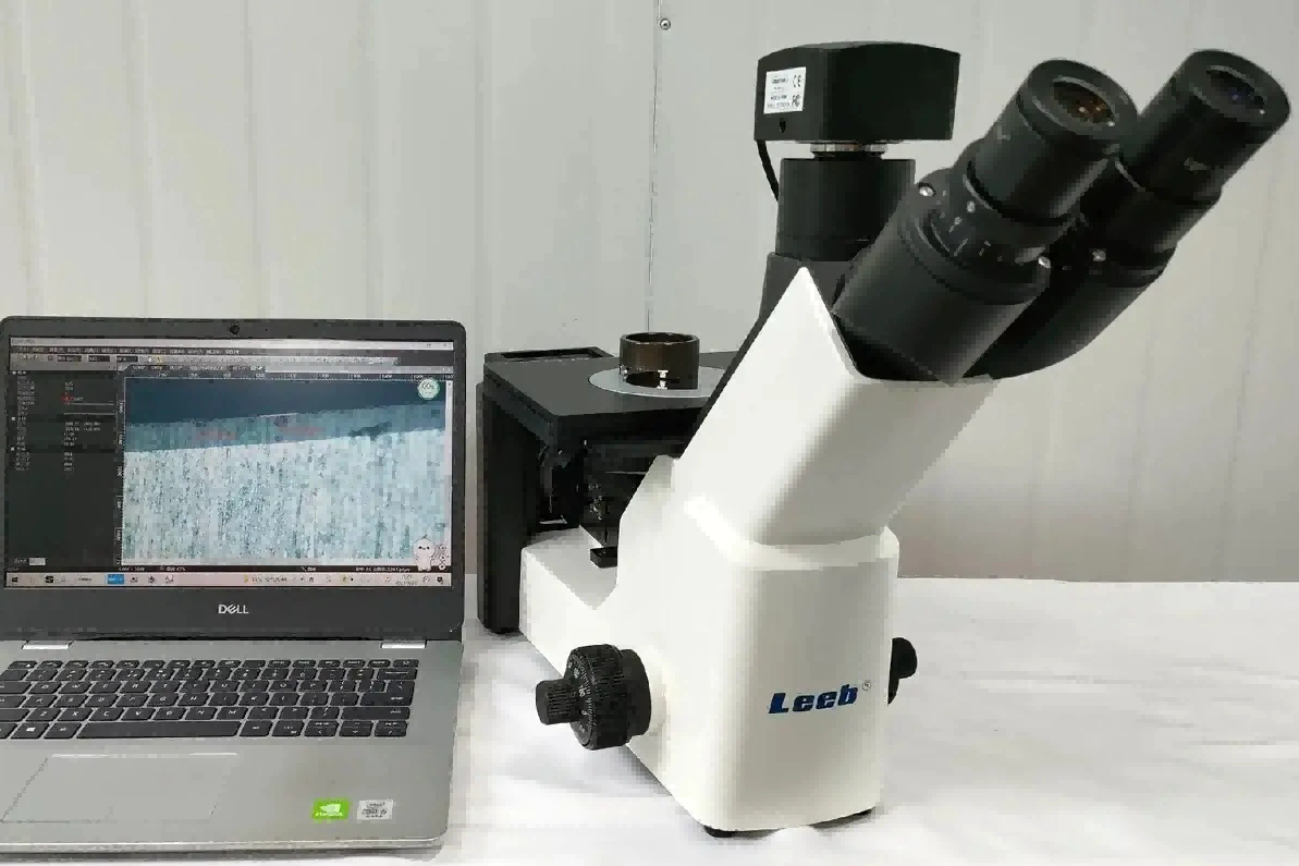
Optical metallography can document grain size, inclusion morphology, phase distribution, surface layer depth, crack path, porosity and weld structure. Brightfield images often handle routine grain and inclusion review. Polarized light can help with some anisotropic structures. Differential interference contrast can improve topographic contrast after preparation. Digital measurement can support grain size, layer thickness or inclusion rating when the fields and method are defined. Metallography should be combined with hardness testing, dimensional inspection, chemistry review, NDT or fracture evidence when the micrograph alone cannot prove the cause. The report should say whether the observations represent one section, several fields or a broader material condition.
Interpreting Microstructures in Common CNC Materials
Austenite, Ferrite, and Carbides in Stainless Steel
For austenitic stainless steels such as Stainless Steel SUS304, metallography can show austenite grain structure, annealing twins, ferrite stringers, carbide precipitation and sensitization risk. A clean-looking machined surface does not prove that the material has the correct microstructure after forming, welding or heat exposure. Carbide precipitation at grain boundaries can reduce corrosion resistance in some service environments. Ferrite balance may matter for welds. A buyer should state whether the inspection target is corrosion resistance, weld quality, inclusion content, grain size or a surface-damage question. The same stainless grade can require different acceptance logic in medical, food, chemical or general industrial service.
Grain Size, Particles, and Overheating in Aluminum Alloys
In Aluminum 6061-T6, optical metallography can help review grain structure, eutectic particles, porosity, deformation bands, overheating and surface damage. The strengthening precipitates that create the T6 temper may be too fine for routine optical confirmation, so metallography should not replace hardness, conductivity or material certificate review when temper verification is the key question. Overheating or incipient melting can show at grain boundaries and can reduce mechanical performance. Soft aluminum also smears during preparation if polishing is not controlled. Buyers should define whether the plan is checking stock condition, machining damage, weld effects, anodizing interface or heat-treatment exposure.
Alpha-Beta Morphology and Heat-Treatment Response in Titanium Alloys
For parts produced via titanium alloy machining, alpha-beta morphology can affect strength, fatigue behavior, fracture toughness and corrosion response. Equiaxed alpha, transformed beta, lamellar regions and prior beta grain structure can each signal different thermal or forming histories. Titanium also requires careful preparation and etching because poor contrast can hide phase relationships. A buyer should not approve a titanium microstructure only from an alloy name. The RFQ should include grade, annealed or heat-treated condition, expected alpha-beta structure, critical surfaces and whether the result supports fatigue, corrosion, medical or aerospace requirements.
Carbides, Segregation, and Stability in Corrosion-Resistant Superalloys
For components produced by superalloy machining, such as Hastelloy C-276, metallography should focus on the features that actually matter for the alloy family. Hastelloy C-276 is commonly evaluated for grain structure, segregation, carbides, intergranular attack risk and effects of welding or heat exposure. It should not be treated like a gamma-prime strengthened nickel alloy unless the specified grade requires that mechanism. For high-temperature nickel alloys, precipitate stability, carbide distribution and grain-boundary condition can influence creep or fatigue. The acceptance basis must come from the material standard, service environment and drawing requirement.
Key Metallography Applications Throughout the CNC Manufacturing Process
Incoming Material Inspection: Verifying Stock Before Machining Risk Accumulates
Incoming material review can use metallography to check whether the supplied stock matches the expected microstructural condition before machining time is invested. For stainless steel, that may include grain structure, inclusions, carbide precipitation or banding. For forged or rolled materials, section orientation matters because longitudinal and transverse views can show different evidence. The buyer should define whether the goal is lot screening, supplier dispute support or release of a specific part family. Metallography is strongest when paired with material certificates, hardness data and drawing requirements. It should not be used as a vague “quality check” with no acceptance rule.
Heat Treatment Validation and Surface Hardening Review
The quality of heat treatment processes can often be checked by reviewing grain structure, phase transformation, decarburization, carbide distribution and surface-to-core differences. For steel quenching and tempering, metallography may show martensite, bainite, pearlite, retained austenite indicators or excessive grain growth, depending on alloy and preparation. For components subjected to nitriding, a section can support review of compound layer condition and diffusion zone depth when the method and acceptance limit are specified. Buyers should connect metallography with hardness traverse data when the question is case depth or surface hardening performance.
Welding, EDM, and Local Heat-Affected Features
Welded joints, EDM surfaces and locally heated features often create microstructural gradients that dimensional inspection cannot explain. Metallography can examine weld metal, fusion line, heat-affected zone, grain growth, lack of fusion, porosity and microcracks when the section crosses the suspected region. For surfaces processed by EDM, the question may involve recast layer condition, microcracking or heat-affected depth before finishing. The inspection plan should state whether the surface will be removed by grinding, polishing, coating or passivation. That decision affects whether a local thermal layer is acceptable, must be reduced or requires process change.
Failure Analysis: Separating Material, Process, and Service Causes
When a CNC machined part fails early, metallography can help separate fatigue, corrosion, overload, heat damage, inclusions and processing defects. A fatigue crack may start at a machining mark, inclusion, sharp transition or surface treatment defect. Corrosion-related failure may show pitting, intergranular attack or corrosion-assisted cracking. A fracture near a weld can involve brittle phases, hard zones or lack of fusion. Metallography should not work alone in failure analysis. The plan should preserve fracture evidence, review service loading, check hardness, examine surface condition and compare the failed region with an unaffected region. For RFQ clarity, include time in service, load direction, environment, cleaning history, coating condition and whether the fracture surface must remain intact. If sectioning would destroy the only fracture evidence, photography and nondestructive documentation should happen first. The buyer decision may be redesign, process correction, material rejection or additional validation.
Supplier Workflow: Connecting Metallography with CNC Process Control
A practical supplier workflow starts with the inspection question, then connects sample selection, sectioning, preparation, etching, imaging, interpretation and disposition. The workflow should record the material grade, heat-treatment state, stock route, drawing revision, critical dimensions, finish condition and suspected risk. If the report will support product release, the purchase order should define the standard and acceptance limit before the sample is cut. If the report will support engineering learning, the plan can be broader, but the conclusion should still state its evidence boundary. This prevents a useful micrograph from being stretched into a claim that the whole lot or every feature is acceptable.
The same workflow should change with production stage. During low-volume production, metallography may confirm whether a heat treatment, weld sequence, surface hardening step or machining allowance is safe before scaling. During mass production, the plan may shift toward lot sampling, abnormal-condition review or supplier quality confirmation. The buyer should decide whether the report is for design validation, process release, supplier dispute, corrective action or recurring monitoring. Each purpose needs different sample count, traceability and acceptance wording.
Metallography also needs to connect with upstream and downstream manufacturing. A supplier offering one-stop service should not treat microscopy as an isolated final check. Cutting strategy, heat treatment, welding, EDM, grinding, deburring and surface finishing can all change the observed structure. For example, CNC grinding may affect a hardened surface if wheel condition, coolant or stock allowance is poor. The report should therefore connect the observed feature to a process variable and a buyer action, not only list what appears in the image.
Engineering Scenarios: How Metallography Supports Decisions
Scenario 1: Gear Tooth Pitting After Grinding
Consider an automotive gearbox gear that shows early pitting near the tooth flank. A metallographic section through the damaged area could look for white etching layer, retempered martensite, microcracks or excessive surface heating. If the evidence supports grinding burn, the next action is not simply to reject one gear. The buyer should review wheel dressing, coolant delivery, stock removal, surface hardness and final finishing requirements. The same section may also show whether the problem is local to the grinding process or linked to earlier heat treatment.
Scenario 2: Coating Interface Review on a Heat-Exposed Blade
For an aerospace blade or similar heat-exposed component, metallography can examine coating thickness, interface condition, oxide layer, diffusion zone and substrate microstructure. The buyer should define whether the inspection is checking bond quality, thermal exposure, coating damage or service-related degradation. If the section shows an abnormal interface, the next step may involve coating process review, surface preparation review, additional microscopy, hardness testing or service condition analysis. The important point is the decision boundary: a single section can support a targeted engineering conclusion, but it should not be used to certify every blade unless the sampling plan supports that scope.
Scenario 3: Inclusion Screening in Implant-Grade Raw Material
For a medical device component, a metallographic section may be used to review inclusion type, size, distribution and location before machining or final release. Inclusions near high-stress regions or corrosion-sensitive surfaces can be more important than inclusions in low-risk areas. The plan should define the material standard, acceptance limit, sample orientation and field count. If excessive inclusions are found, the buyer action may be to quarantine the lot, request mill evidence, perform additional sampling or change material source. The report should support traceable risk control, not make a broad biocompatibility claim by itself.
Beyond Quality Control: Using Microstructure to Reduce Lifecycle Risk
Metallographic data can reduce lifecycle risk when it is tied to a known mechanism. Grain size can influence strength and toughness. Carbide distribution can affect wear, corrosion or embrittlement. Inclusions can become fatigue initiation sites under cyclic loading. Surface layers can affect contact stress, sealing, corrosion resistance or coating adhesion. These relationships are conditional. They depend on alloy grade, geometry, loading, temperature, environment, surface finish and acceptance standard. A responsible report should explain what the observed microstructure supports and what still requires other evidence.
The strongest use of metallography is therefore not prediction in isolation. It is the combination of microstructure, drawing risk, material certificate, hardness, dimensional results, process history and service assumptions. A thin wall may move after unclamping even if the material microstructure is acceptable. Powder coating or anodizing may change bore size without changing the base microstructure. Tool wear may change burr formation or surface damage without changing grain size. Buyers should use metallography to answer the material question, then connect that answer with the manufacturing and inspection controls that affect the finished part.
For precision machining projects, a useful RFQ should include alloy grade, condition, heat treatment, stock form, critical features, suspected defect, sample location, standards, acceptance criteria and whether destructive sectioning is allowed. The RFQ should also ask what the report will not prove. A single cross-section may not prove full-lot uniformity, final dimensional acceptance, fatigue life, corrosion life or coating adhesion unless the sampling and test plan covers those claims. If those inputs are clear, metallographic microscopy can provide evidence that supports material release, process correction, failure analysis or production transfer. If those inputs are missing, the result may still be visually clear, but its decision value will be weak.
Frequently Asked Questions (FAQ)
Does metallographic analysis require destructive sampling of my parts?
What specific types of defects or features can metallographic analysis detect in materials?
What is the typical lead time from submitting samples to receiving a metallographic analysis report?
Which international standards do Neway’s metallographic analysis services comply with?
How can I develop a tailored metallographic analysis plan that meets my material requirements?