Precision Height Gauge Inspection for CNC Machined Parts
The Core Role of Precision Height Gauges in CNC Quality Management
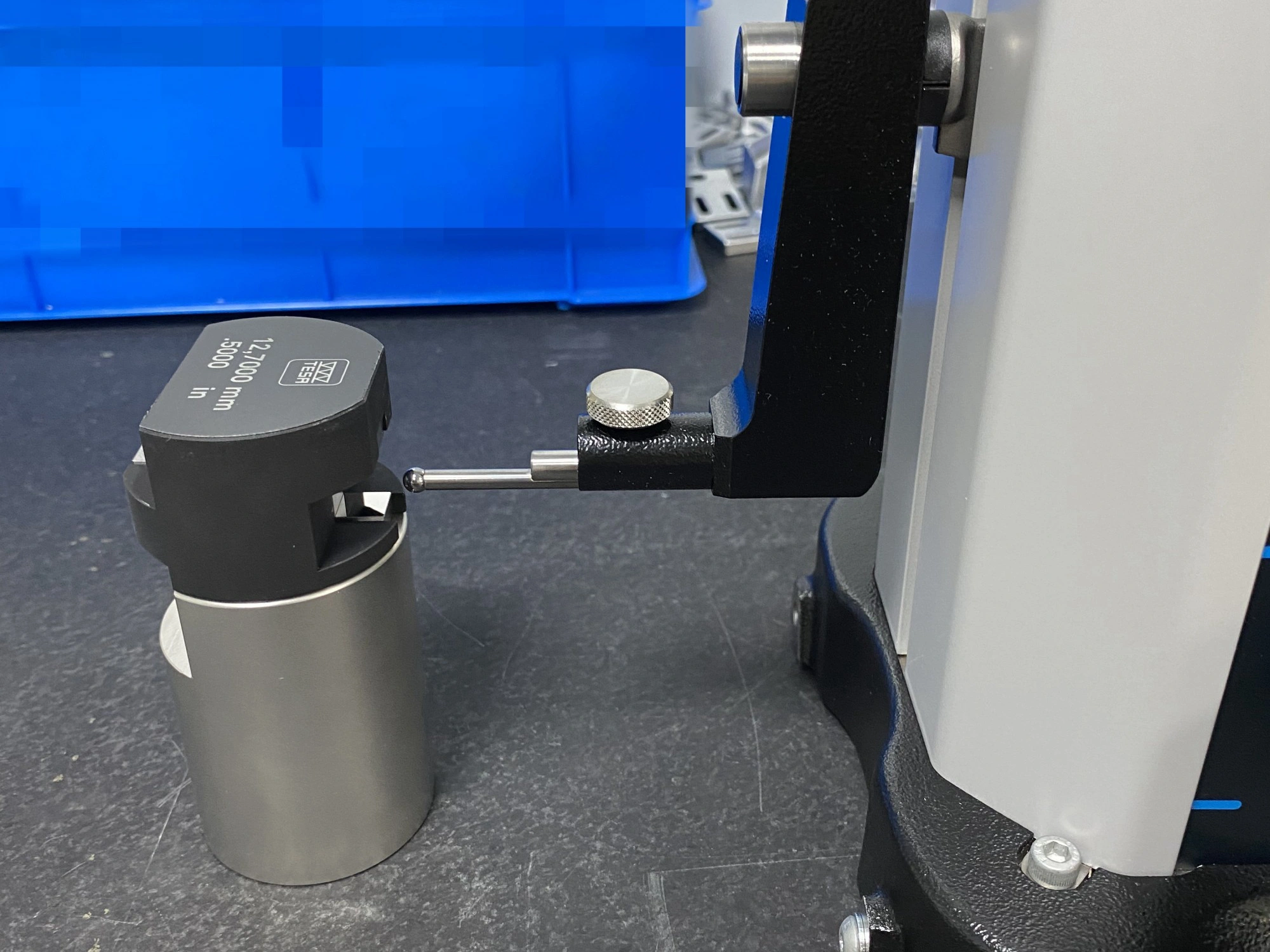
Precision height gauge inspection is a practical method for checking height, step, depth, flatness-related comparisons and datum-to-feature relationships on CNC machined parts when the feature can be contacted from a stable reference plane. The method is strongest on open vertical features, shoulders, bosses, slots and hole-depth checks that can sit securely on a precision granite surface plate. It is not a replacement for CMM inspection, optical scanning or dedicated gauges when the drawing controls complex position, freeform geometry or inaccessible internal features. For quote review, a height gauge is best assigned to shoulder heights, spacer faces, counterbore depths, boss height spread and simple datum-to-plane checks. It is less suitable for a profile tolerance, a compound-angle feature, a flexible thin wall without support, or a part that cannot repeatably rest on the chosen datum. Buyers should treat height gauge data as one part of the inspection plan and ask which dimensions will be checked by height gauge, which will be checked by another method, and what decision rule applies. That answer prevents a supplier from promising a tight drawing tolerance by only naming an instrument.
For CNC buyers, the value of height gauge inspection is speed with traceability. A machinist or inspector can confirm a machined shoulder, counterbore depth, sealing face height or mounting pad step before more parts are released. On automotive engine components, that fast feedback can show whether a datum face shifted after roughing, whether a burr is lifting the part, or whether a tool offset has started to drift. On aluminum 6061-T6 brackets and covers, the same check helps separate true machining error from part movement after unclamping. The method also helps detect a practical failure mode: a thin wall can move after the fixture opens, so the final height may differ from the in-machine offset. Another useful signal is repeatability across operators. If two trained inspectors cannot repeat the same height within the agreed measurement plan, the buyer should question the method before questioning the part. The buyer action is simple: mark critical height, step and depth dimensions on the drawing and state whether the supplier must report actual measured values or only pass/fail results.
Working Principle and Accuracy Grades of Digital Height Gauges
A digital height gauge measures vertical displacement from a reference surface by moving a probe, scriber, depth attachment or contact tip along a precision scale. The displayed resolution may be very small, but the usable inspection result depends on the gauge specification, surface plate condition, probe geometry, part support, measuring force, temperature and calibration status. Resolution is not the same as measurement uncertainty. A common mistake is to read the smallest display increment as the guaranteed part tolerance. A supplier can use the method well only when the datum surface is clean, the part is stable, and the measurement strategy matches the drawing callout for materials such as stainless steel 316L or titanium alloy components. Buyers should request the gauge model, calibration status, probe attachment and stated inspection method when a height result is close to the tolerance limit. The report should also show whether the value is a single point, an average, a maximum spread or a comparison to a master feature.
Temperature control matters because most dimensional specifications assume the reference temperature of 20 °C used in dimensional metrology. A part, a surface plate and the gauge scale do not always expand at the same rate, so thermal soak time can be more important than the display resolution. This is a common risk for larger aerospace components, long aluminum housings, stainless frames and mixed-material assemblies. Plastics can add another risk because moisture absorption, relaxation and clamping history may change the measured height. A height gauge with compensation still needs a defined inspection environment and a documented method. Buyers should ask whether the quoted tolerance is evaluated at a controlled temperature, after part stabilization, and with a guard band or decision rule such as the one described by ISO 14253-1 for acceptance decisions.
Five-Step Implementation Standard: From Reference Establishment to Data Recording
A reliable height gauge workflow starts with the drawing, not with the instrument. Step one is to identify the controlled feature, datum reference, tolerance type and inspection state. Step two is to prepare the contact surfaces by removing chips, oil film and burrs that can lift the part. Step three is to place the part on a clean precision granite surface plate or approved fixture so the datum condition matches the drawing as closely as possible. If the part uses a datum target, an angled rest, or a functional fixture, the setup should simulate that condition instead of forcing the part flat. Step four is to zero or verify the gauge with suitable setting artifacts, then measure at defined points. Step five is to record actual values, environmental conditions, gauge identity and the acceptance decision. For repeat orders, the work instruction should keep the same contact tip, datum support and measurement point definitions unless a drawing revision changes the requirement.
This sequence also protects the buyer from misleading data. If a feature created by multi-axis CNC machining is measured from the wrong temporary surface, the number can look precise while the datum relationship is wrong. If a deep step is checked with a contact tip that cannot sit squarely, cosine error or side contact can hide the real depth. If only pass/fail marks are stored, later process drift is harder to investigate. For a production lot, actual-value reporting on a few trend dimensions can be more useful than 100 percent pass/fail marks with no measured numbers. A useful dimensional inspection report should name the inspected dimension, datum setup, tool or probe attachment, sampling stage, measured values and the action taken when a result approaches the limit. The same report should avoid mixing inspection stages. First-article data, in-process control data and final-release data answer different questions, even when the same height gauge is used.
Typical Measurement Case Analysis (Plane Distance / Hole Depth / Step Height)
Height gauge inspection is most useful when the measurement question can be reduced to a controlled vertical comparison from a stable datum. For surgical trial instruments, fixture plates or non-implant tooling used around medical device manufacturing, a height gauge can check step height, platform difference and hole depth before final acceptance by the specified method. For plane distance, the inspector should state whether the result is taken at one point, several functional points, or the highest and lowest measured positions. The same measurement is weaker when the functional requirement is true position, profile or surface texture. A buyer should not ask for height gauge inspection as a blanket requirement. The RFQ should specify which heights need actual values, which holes need depth verification, and which GD&T features require CMM or dedicated gauges.
A practical example is a machined electronics housing with a gasket face, several screw bosses and a shallow internal pocket. The height gauge can compare boss height to the gasket datum, check pocket depth after tool change, and detect whether a burr under the housing changes the measured plane. A 25-point grid may be useful for a broad mounting surface, but the grid is only meaningful if the drawing asks for flatness, coplanarity or a related functional check. If high points cluster near clamp locations, the likely issue may be support distortion or local release movement. If high points follow a cutter path, the likely issue may be tool deflection or wear. When a trend appears, the measurement result should feed back to the CNC precision machining services route, including tool offset, fixture seating, roughing allowance, deburring method and inspection timing. That feedback is more valuable than recording a pass/fail mark with no process context.
Out-of-Tolerance Analysis and Process Corrective & Preventive Measures
An out-of-tolerance height gauge result should first be separated into three possible sources: measurement setup error, part handling error and true machining error. Setup error includes a dirty surface plate, worn contact tip, wrong zero, tilted part, unstable support or measurement force that bends a thin wall. Handling error includes burrs, chips, clamping marks, heat from machining, or a part measured before thermal stabilization. True machining error may come from tool wear, tool deflection, fixture shift, stock movement, datum transfer error or an incorrect offset. If repeated checks by the same operator disagree, the issue may be the measurement system. If repeated checks agree but the part fails, the machining route needs review. A short recheck with a second operator or alternate contact tip can prevent unnecessary offset changes. The first containment action is to re-clean, re-zero, re-seat and remeasure the same feature before changing the CNC process.
Once the measurement method is confirmed, the pattern of the data points to the next action. A uniform shift across many automotive engine components may indicate a tool offset, fixture stop movement or thermal drift. A corner-only error can suggest clamping distortion, uneven support or chip packing under the datum. A depth error that changes after deburring may show that burr height was part of the original reading. Acceptance should follow the drawing tolerance and the agreed measurement decision rule, not a verbal promise that the part is probably usable. The buyer should ask the supplier to record the suspected cause, immediate containment, corrected process setting, reinspection result and any change to sampling frequency. That record helps decide whether the lot can continue, needs sorting, or needs a new machining route.
Integrated Composite Inspection Scheme with CMM
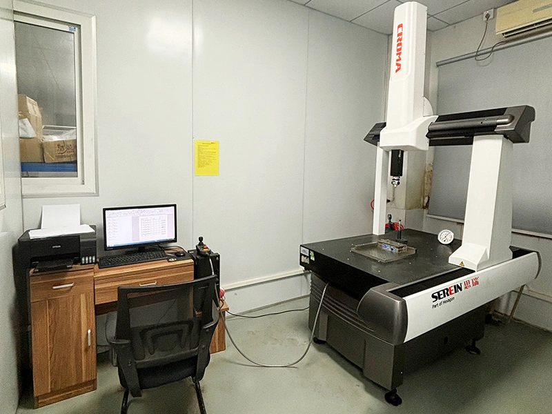
Height gauges and CMMs serve different inspection decisions. A height gauge is efficient for open vertical dimensions, repeated step checks, quick process feedback and simple depth verification. A CMM is better for feature position, 3D datum systems, profile, angled surfaces and complex relationships that cannot be reduced to a single vertical comparison. For example, a height gauge may confirm that a boss is the correct height above a base datum, while a CMM may be required to verify the boss position relative to two perpendicular datum planes. Profile tolerances, compound angles and hidden internal geometry normally need another method. A strong inspection plan assigns each drawing characteristic to the method that can measure it with enough access and uncertainty margin. The dimensional inspection report should not merely list equipment names. The report should show why each method was chosen and how close each result was to the tolerance boundary.
For a critical aerospace components lot, height gauge inspection may be used for fast in-process control while selected pieces move to CMM verification under the approved sampling plan. That does not mean every height gauge result is automatically interchangeable with a CMM result. Measurement system analysis, gauge repeatability, operator method and datum simulation still matter. If the sampling plan changes after a nonconformance, the reason should be visible in the quality record. If a dimension is safety-critical or near the limit, the buyer should ask whether the inspection method has enough uncertainty margin. The buyer should also confirm whether first-article inspection, in-process checks and final inspection use the same datum scheme or intentionally different checkpoints. A mismatch between these stages can create a dispute even when every single reading was taken carefully.
Industry-Specific Requirements (Aerospace / Medical Implants)
Industry requirements change the documentation burden more than the basic height gauge principle. Aerospace drawings may require traceability of the part number, revision, serial or lot number, gauge identity, calibration status, inspector, inspection date and nonconformance disposition. Medical-related machining may require cleaner handling, defined inspection records and tighter control of surface damage, depending on whether the part is an implant, instrument, fixture or production aid used in medical device manufacturing. For both sectors, the inspection plan should identify controlled dimensions before production starts. A height gauge can support these requirements only when the inspection method is documented. The method does not by itself prove industry compliance.
Material and surface condition also affect the inspection decision. A machined stainless steel 316L component may show different burr behavior from aluminum, titanium or polymer parts. Electropolishing, passivation, anodizing or coating can change edge condition, hole entry and functional height relationships. Surface treatment after inspection can reduce a bore edge, build up a shoulder, or change how a part sits on the datum surface. If height is inspected before finishing but function depends on the finished surface, the buyer should define both states or specify the final acceptance state. This is especially important for sealing faces, bearing shoulders, locating pads and threaded bosses. The RFQ should include drawing revision, material condition, finish sequence, critical dimensions, inspection standard, report format and any required lot traceability.
Supplier Metrology Evidence Buyers Should Request
A supplier’s height gauge capability should be judged by evidence, not by equipment names alone. Useful evidence includes gauge model and range, calibration certificate status, surface plate grade and maintenance, gauge blocks or setting artifacts, operator work instruction, environmental control, uncertainty or guard-band practice, and records showing how out-of-tolerance results are handled. A buyer can also ask whether the supplier separates setup verification, in-process control and final acceptance. Those are different activities. A fast shop-floor check can protect the process, while a final acceptance record needs a clearer datum setup, traceable gauge identity and a documented decision rule. When the tolerance is narrow, the supplier should explain whether the height gauge is used as the final acceptance tool or only as a process-control tool before CMM confirmation. If the supplier cannot map each critical dimension to a method, the quote may look complete while the inspection risk remains unresolved.
For small-batch prototypes, height gauge inspection can quickly confirm whether the machined geometry is close enough for assembly learning before investing in a full inspection program. For production CNC precision machining services, the same method should be tied to sampling frequency, reaction plan, revision control and report retention. The best RFQ is specific: list the height, step and depth characteristics, define the datum state, identify any CMM-only GD&T features, state whether actual values are required, and ask the supplier to return the proposed inspection plan with the quote. For a transferred production project, include the previous inspection method, known measurement disputes, finishing state and any dimensions that drove earlier scrap or rework. If the drawing has no inspection notes, attach a characteristic list with priority levels, expected report fields and the production stage for each check. The final purchasing decision should compare the inspection plan, not only unit price or promised lead time. Clear inspection scope also reduces later disputes between purchasing, design engineering and incoming quality control. That gives purchasing, engineering and quality teams a common basis for comparing suppliers without relying on unsupported accuracy claims.
Frequently Asked Questions