How do I know which dimensions on my part require tight tolerances?
How Do I Know Which Dimensions on My Part Require Tight Tolerances?
Insights from a Neway Manufacturing Engineer
As part tolerancing grows more critical in global industries like aerospace, EVs, and medical devices, understanding which features truly require tight tolerances is essential for balancing performance, cost, and manufacturability. At Neway, we regularly help clients identify unnecessary ±0.005 mm specifications that add machining time and cost without improving function.
When Tight Tolerances Are Justified
1. Functional Fits and Mating Surfaces
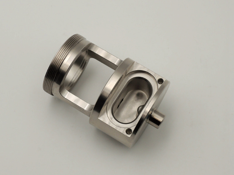
Any dimension that determines fit, load-bearing alignment, or fluid/gas sealing should receive priority tolerancing. Examples:
Shaft diameters with press fits: H7/g6 fits may require ±0.01 mm
Precision alignment holes: Tolerance range of ±0.01–0.02 mm
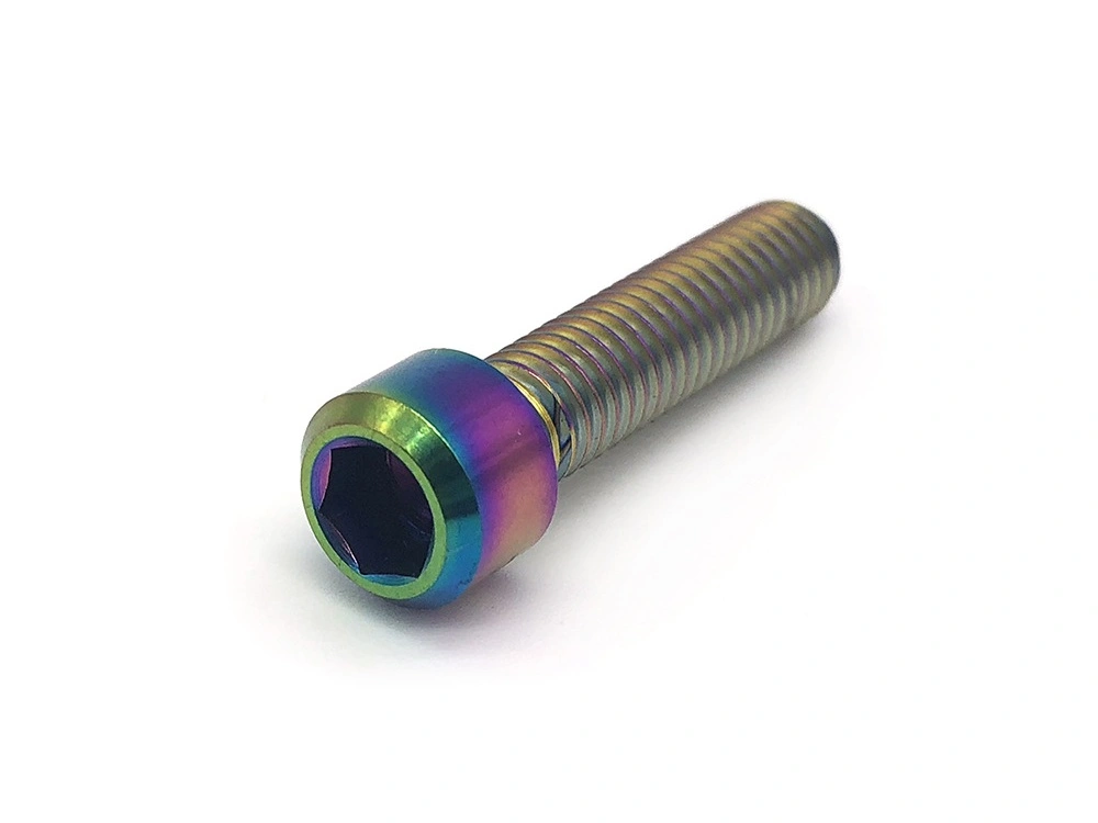
Threaded interfaces: ISO/ANSI class 2 or 3 threads should be verified with thread gauges
These are critical in robotic actuators, aerospace linkages, and surgical tool assemblies.
2. Moving or Load-Sensitive Assemblies
For dynamic parts—e.g., sliding components or rotating assemblies—tight tolerances control wear, vibration, and thermal expansion offset:
Positional tolerance: ±0.01 mm or geometric callouts like true position
Flatness and perpendicularity: 0.02 mm per 100 mm is standard in medical or optics
3. Stack-Up in Multi-Part Assemblies
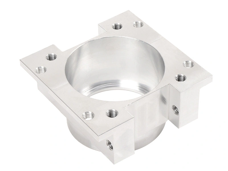
Where multiple machined parts are assembled in sequence, cumulative errors stack. Examples include:
Stack height tolerance: ±0.05 mm across 3–5 components
Surface parallelism: ≤0.01 mm for gear housings or valve bodies. Exceeding stack-up specs leads to misalignment and downstream failure.
4. Regulatory Compliance Dimensions
Some dimensions are driven by international standards or certification requirements:
Aerospace AS9100/ISO2768 critical dimensions
Medical device ISO 13485 validated surfaces
EV battery casing tolerancesare defined by UL or IEC standards
Apply tight tolerances only where function or compliance demands it.
Efficient Tolerancing: What to Loosen
Feature Type | Suggested Tolerance |
|---|---|
Cosmetic features | ±0.1 mm or more |
Non-critical holes | ±0.05 mm standard |
Logo surfaces | General tolerances only |
Chamfers, radii | ±0.2 mm unless mated |
Neway engineers frequently revise tolerance stacks by >30% without altering function, improving machining efficiency and reducing inspection burden.
Our Approach to Tolerance Review
As part of our DFM process, Neway engineers will:
Evaluate 2D and 3D files using CAD simulation
Flag over-toleranced or impractical dimensions
Recommend alternate GD&T or fits based on ISO/ASME standards
Validate critical dimensions with CMM inspection
We also advise clients to conduct early tolerance stack-up analysis, especially for multi-part assemblies or sealed enclosures.
Optimize Your Tolerancing with Neway
Neway Machining provides CNC components with verified ±0.005 mm tolerance capability and full FAI reporting. We help you reduce cost and lead time by identifying where tolerances matter—and where they don’t—across industries like aerospace, medical, and automation.