Precision Boring Services: Bore Geometry, Datum Transfer, and Verification
Precision Boring Services: Bore Geometry, Datum Transfer, and Verification
Precision boring services are best selected by the bore geometry, datum chain, access limits, material state, and evidence required for the finished part. Boring is a controlled way to establish or correct an internal diameter and its relationship to other features, but it is not a generic guarantee of straightness, location, or assembly fit. Buyers should define the bore function, preceding stock condition, support state, inspection frame, and change records before comparing suppliers. A precision boring route review helps organize those questions without replacing the controlled drawing.
Define What the Bore Must Do
Start with the function of the bore rather than the tool name. A bore may locate a bearing, guide a shaft, contain a seal, provide a clearance cavity, or establish a coaxial relationship between assembled halves. Each function changes which diameter, form, axis, surface, and edge conditions matter. State the mating hardware, load or motion, environment, lubricant, temperature, and assembly sequence when they influence acceptance. A nominal diameter alone does not describe the decision.
Separate bore size from form and location. Diameter can be within limit while taper, ovality, cylindricity, or axis position prevents assembly. A smooth surface can still be mislocated, and a successful trial fit does not prove the specified geometric relationships. Write each characteristic with its datum frame, measurement state, and evidence owner. If a split housing is assembled before final boring, state whether the released condition is the assembled pair or the individual half.
Use the Split-Housing Views as a Geometry Prompt
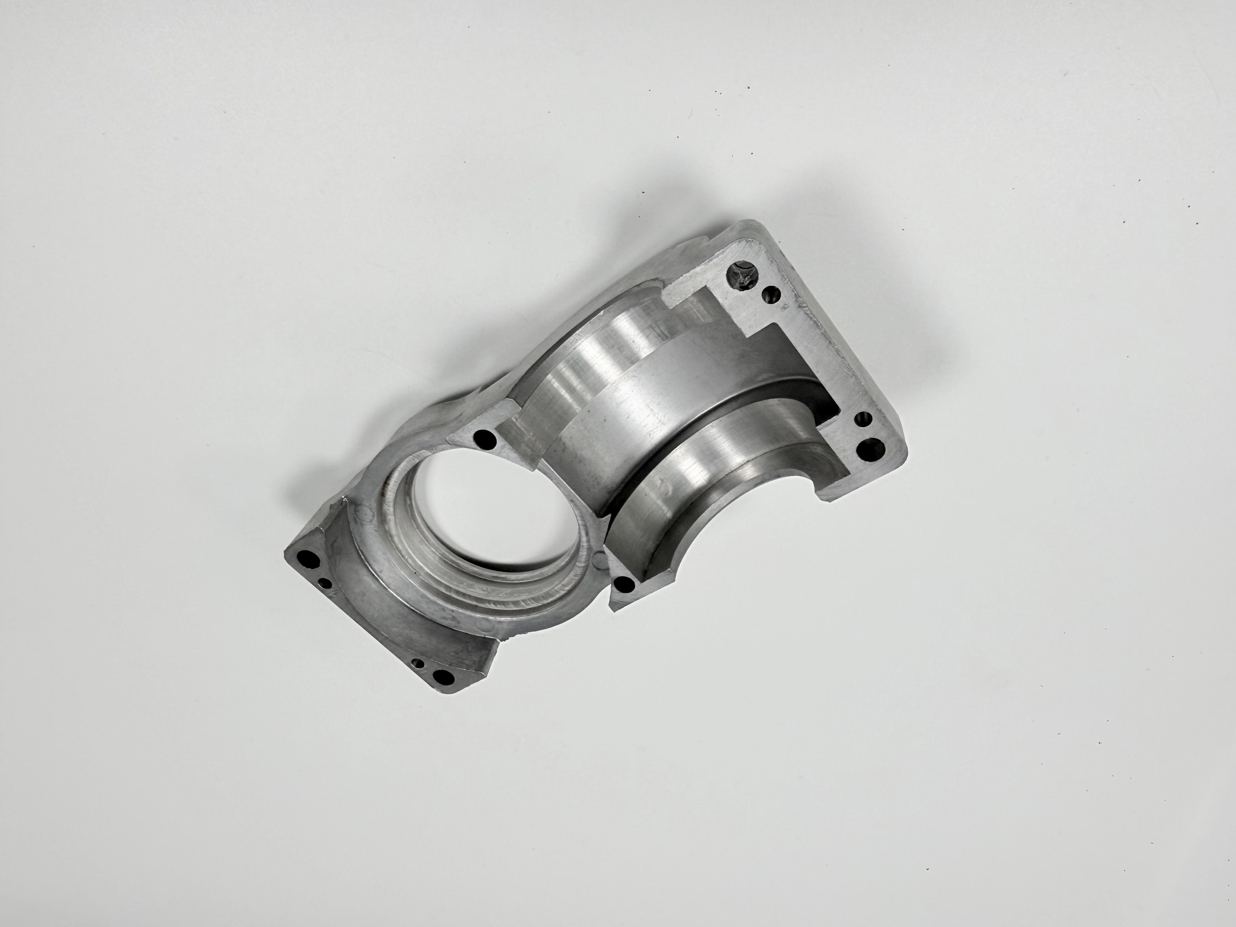
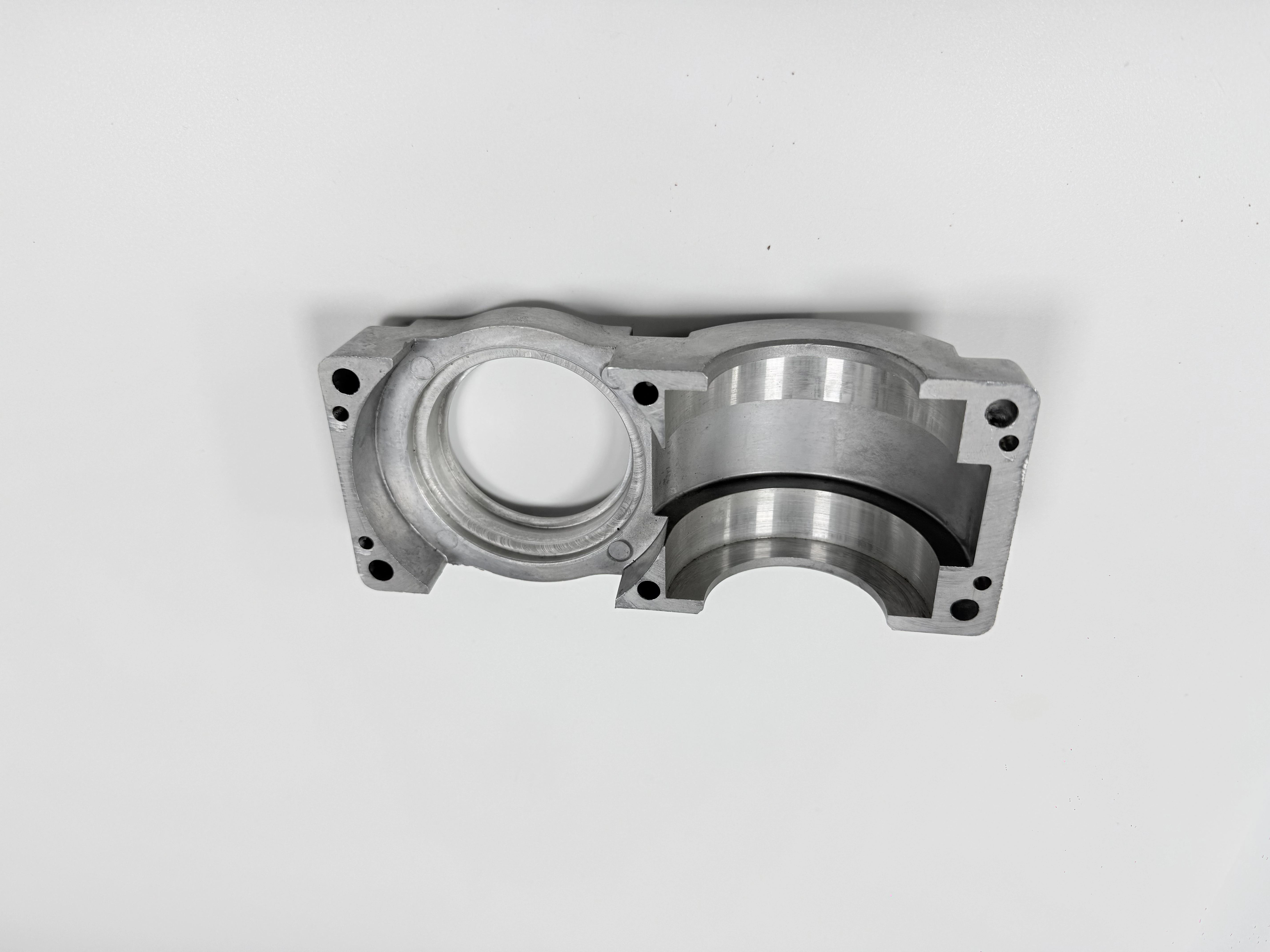
The paired images show one split housing or bearing-seat-like component with circular bore seats, stepped cylindrical surfaces, mounting holes, and a machined split profile. The two views confirm the same physical product and different angles. They do not reveal alloy, heat treatment, bore size, tolerance, load, bearing type, or production status. Use the visible geometry to ask about access, parting-line control, and datum transfer; use the drawing and measured records for every engineering conclusion.
Choose Boring After the Preceding Process Is Known
Boring may follow milling, drilling, turning, casting, forging, welding, or heat treatment. The preceding process determines stock distribution, entry location, interrupted cuts, burrs, hard layers, and the datum available to the boring setup. A route that works for a stable rough-machined block may not work for a casting with variable wall thickness. Record the entry diameter, allowance, surface condition, and expected distortion before selecting the finish operation.
Consider whether drilling, reaming, interpolation, line boring, or single-point boring best answers the function. A process can establish size while leaving an unresolved axis relationship. A CNC milling reference can frame the faces and pockets created upstream, while a turning reference can frame an existing cylindrical axis. These references organize route questions; they do not prove a specific bore result.
Control Entry Condition and Stock
Measure rough bore size, center location, form, and stock distribution with the support and datum that the next operation will use. Record whether a hole is open, blind, interrupted, or intersected by a cross passage. Local stock can change cutting force and tool deflection, while insufficient stock can leave drill wander or a damaged layer. Establish a lower and upper entry window for each bore rather than quoting one generic allowance.
When heat treatment, stress relief, coating, or welding occurs before boring, identify the state transition and repeat the checks that can move the axis or diameter. A material certificate supports identity within scope; it does not prove the bore's final geometry. Keep pre-process and post-process results together. If a component is supplied as a split pair, identify whether the halves remain matched and how that identity is maintained through cleaning and handling.
Build a Datum Chain That Survives Setup Changes
The boring datum should represent the functional relationship and be repeatably located. Name primary, secondary, and tertiary references, contact order, support points, clamp direction, and any transformation from a convenient fixture surface. A mounting face can orient a housing while a bearing seat controls the functional axis; using the wrong surface can create a repeatable but mislocated bore.
Record whether the part is measured free, restrained, assembled, or paired with a mating half. Flexible walls and split lines can move under clamp force. If the fixture uses replaceable locators, soft jaws, shims, or adjustable supports, identify their revision and qualification. A fixturing reference can help structure contact and support questions, but a fixture claim is not proof of datum transfer.
Register Split Halves Before Boring
For a split housing, define how the two halves are joined, torqued, cleaned, and oriented before any shared bore is cut. State fastener condition, joint gap or seating rule, locating features, and the identification linking the halves. If each half is machined separately, specify which relationships are created independently and which are verified only after assembly. Do not assume that matching serial numbers prove that the halves were processed together.
Use witness features or a controlled assembly check when the part is reoriented. Record contact sequence and the condition of the split faces. Burrs, chips, coating, or a damaged joint can lift one half and shift the bore axis. If a joint is opened after boring, state whether reassembly requires a repeat check. Preserve the original state and any subsequent correction so the final record remains chronological.
Control Tool Reach, Deflection, and Bore Access
Tool reach and stiffness influence a bore differently from an open external face. State bore depth, diameter-to-length relationship, shoulder access, entry chamfer, cross holes, interrupted surfaces, and chip evacuation. A long slender tool can deflect, while a large interrupted cut can change load as the edge enters and exits material. A machine envelope or spindle rating does not prove the finished axis, form, or surface.
Choose tool geometry, holder support, insert condition, coolant delivery, and pass sequence for the actual material and entry state. Record what may be adjusted during the run and what requires approval. If a bore seat has a step or relief, define which surface controls the tool path and which is merely clearance. For deep or obstructed bores, state how the tool is qualified and how an inaccessible region will be verified.
Monitor Cutting Response
Use measurable signals such as load trend, chatter, tool wear, size drift, surface response, or chip evacuation to trigger a check. A stable spindle load does not prove axis location. A good surface appearance does not prove roundness or residual stress. Link each response to a reaction, affected unit range, and restart approval. If a tool or holder changes, repeat the CTQs sensitive to stiffness and geometry.
Manage Material and Thermal State
Material designation, hardness, temper, casting condition, weld history, and heat treatment can influence tool wear, cutting force, distortion, and burr formation. State the condition before boring and any stabilization time. Do not infer material or hardness from the silver appearance in the images. If a material substitution is proposed, define which conclusions can transfer and which require a production-state sample.
Control coolant, cleaning, and temperature when they affect measurement or fit. Residual coolant or chips can change seating, while a warm housing can report a different diameter than a stabilized one. If a coated or treated part is measured before the final state, specify the recheck. The delivered condition must be clear: as-bored, washed, coated, assembled, or packaged.
Write a Reaction for Distortion
Define what happens if the bore moves after unclamping, heat treatment, or pair assembly. Hold the affected range, identify the process event, and compare free and restrained measurements when relevant. Re-boring can remove stock and change the datum relationship, so it requires an approved disposition. Preserve the original result and process state rather than replacing an out-of-limit value with a later measurement.
Separate Diameter, Form, Axis, and Surface Evidence
Measure diameter, taper, roundness, cylindricity, coaxiality, location, perpendicularity, roughness, and edge condition with methods suited to each requirement. A plug gauge can indicate a fit at one condition; it cannot prove axis location or form. A CMM report depends on the stated datum alignment and probe access. A bore gauge reports size at sampled depths and angles; it does not automatically prove the entire surface.
Define sections, depths, angular positions, support, temperature, and instrument calibration. For stepped or paired bores, identify the relationship between seats and the common axis. Retain raw data or trace files when the decision depends on more than a displayed value. If a probe cannot reach the bottom or a shoulder blocks a stylus, state the unmeasured region and the alternate evidence needed.
Use a Bore Inspection Plan
| Characteristic | Evidence state | Boundary |
|---|---|---|
| Diameter | Defined depths, angles, gauge, temperature | Not axis or full-form proof |
| Roundness or taper | Section method and alignment | Not material or function proof |
| Axis relationship | Datum frame and accessible features | Not surface-finish proof |
| Fit or function | Specified mating hardware and state | Not unmeasured geometry proof |
The table keeps evidence separate. A quality inspection reference can help assign ownership, while the controlled drawing defines acceptance. If the bore is assembled with a bearing or shaft, record the hardware identity, lubrication, temperature, and insertion method so a fit result is reproducible.
Verify Reorientation and Process Handoffs
Run a transfer check after flipping a housing, changing a fixture, replacing a locator, or moving the job to another machine. Identify witness features, contact sequence, alignment, and the unit sampled. A calibration artifact may demonstrate machine repeatability but cannot demonstrate how a split housing seats. Use the actual geometry and support state for the check.
When boring follows outside processing, preserve the before-and-after datum and material state. Heat treatment, coating, cleaning, or deburring can alter access and seating. Record processor, batch, specification, masking, and reinspection. A certificate supports the processor claim within scope; it does not replace final bore evidence. A metal finishing reference can frame state questions without proving the delivered bore.
React to Fixture, Tool, and Program Changes
Define which changes trigger a first-piece or expanded inspection: fixture, locator, holder, insert, tool path, coolant, machine, material heat, program revision, measurement method, or outside processor. Record effective date, affected units, owner, and rechecked CTQs. Do not rely on a machine reset or a replacement tool number as a substitute for product evidence.
Write an RFQ That Makes Boring Scope Comparable
Attach the controlled drawing and model, revision, material and condition, bore function, entry stock, datum scheme, split-pair assembly state, depth, access, CTQs, surface requirements, inspection method, sampling, records, cleaning, outside processing, packaging, and milestones. Ask suppliers to state their assumed entry window, tool reach, support, coolant, measurement frame, inaccessible regions, and reaction to drift.
Separate setup, fixture, programming, tooling, first-piece, inspection, rework allowance, outside processing, packaging, and freight costs. Request notification before changes to material, fixture, holder, tool, program, coolant, inspection, processor, or packaging. If a supplier offers a single bore price without defining pair registration or evidence, treat that quote as incomplete rather than cheaper.
Ask for a redacted sample record showing unit identity, revision, datum state, bore measurements, raw-data references, deviations, and change history. Require the supplier to identify what is measured on every unit and what is sampled. A machine capability statement can support route discussion, but it does not establish the finished bore for the pictured housing.
Screen the Boring Supplier on Evidence
Compare whether each candidate explains pre-bore stock, datum transfer, split-pair registration, tool access, deflection controls, material state, inspection frame, inaccessible regions, outside-process handoff, and change reaction. A machine list, spindle size, or generic tolerance promise is not evidence for this geometry.
Ask for an anonymized setup or inspection format tied to comparable internal features. Prefer responses that name owners, sample basis, limitations, and release criteria. If a supplier cannot explain how axis, form, and fit are separated, ask for clarification before selecting on price or cycle time. The strongest answer makes the evidence boundary visible.
Release the Bored Part With Explicit Boundaries
Release when revision, material state, entry stock, datum chain, pair registration, tool and fixture records, diameter and form results, axis evidence, surface checks, functional fit, outside-process certificates, packaging, and deviations agree. Hold when a result belongs to another state, an inaccessible region is unaddressed, or the bore cannot be traced to the unit and setup.
Precision boring is a controlled relationship, not a promise attached to a tool name. The split-housing views are useful geometry prompts, but they do not prove size, material, application, or capability. Let the drawing, setup evidence, measured sections, and lot-linked records determine acceptance. A CNC machining route review can support the broader process conversation while the boring inspection plan controls the released characteristic.
Route decisions become clearer when each neighboring operation has a defined handoff. A milling process review can identify the faces and pockets that establish rough-bore access, while a turning process review can identify a cylindrical axis that must be preserved. A fixture planning reference can organize support and clamp questions; a quality inspection reference can organize the evidence owner; and a metal finishing reference can frame cleaning or coating state changes. These references are prompts, not capability proof. The controlled drawing, actual setup, measured sections, and lot trace remain the authority for release.
Before approving a route, ask where uncertainty enters the chain. Entry stock may vary by casting or roughing condition; a datum can shift when a split face is cleaned or clamped; a long tool can deflect under an interrupted cut; and a fit can change after coating or temperature stabilization. Assign a check to each risk and state the reaction when it fails. This converts “precision boring” from a broad label into a sequence of observable decisions that design, quality, and purchasing can review together.
Keep the decision boundary visible in the traveler. Note which dimensions are planned, which are measured, which are sampled, and which require a functional check. If a result is near a limit, retain the raw measurement and identify the support and temperature before deciding on release. This separation prevents a nominally good diameter from hiding a shifted axis or an unverified shoulder.
FAQ