How Should Bore Axis and Datum Transfer Be Planned?
How Should Bore Axis and Datum Transfer Be Planned?
Bore axis and datum transfer should be planned by naming the functional reference, defining how the part is seated, recording the pre-bore state, and verifying the final relationship in the drawing's datum frame. A bore can meet diameter while its axis is shifted, tilted, or misrelated to another seat. The buyer should decide whether the part is located free, restrained, assembled, or paired with a mating half, then require evidence from the actual setup. A machine coordinate or fixture stop is not automatically a functional datum.
Identify the Functional Axis
Write what the bore controls: a bearing seat, guide, seal, shaft, clearance cavity, or common axis between housing halves. State the mating hardware, load, motion, temperature, lubricant, and assembly order when those conditions affect the relationship. Separate diameter, roundness, cylindricity, perpendicularity, coaxiality, and true position. A fit check can reveal interference, but it does not by itself prove the complete geometric control frame.
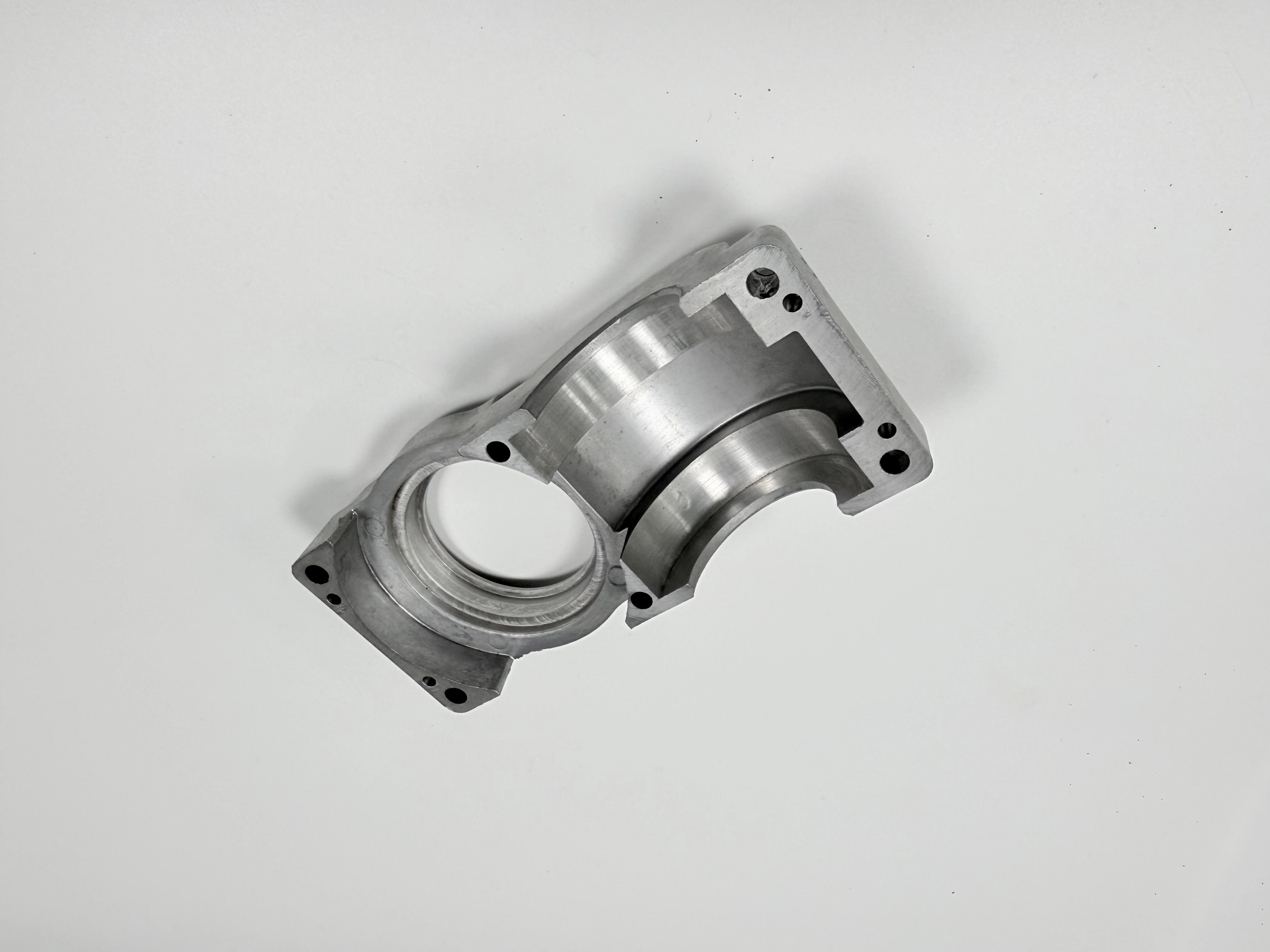
For a split housing, identify whether the functional axis exists only after the halves are bolted together. If the halves are machined separately, define which features are independent and which must be checked after assembly. Keep matched identifiers with both pieces. Do not infer axis function from the photograph: the visible circular seats and split profile show geometry only, not size, material, load, or application.
Record the Datum Before Boring
Measure the reference faces and locating features before boring using the intended support and temperature state. Record flatness, burrs, damage, stock, and any distortion after heat treatment or welding. A long or thin wall can relax when unclamped, so note whether the value is restrained or free. Link the result to unit identity, material heat, revision, fixture, and operator or owner. A certificate supports material identity within scope; it does not prove that the datum is stable.
When the part passes through milling, turning, casting cleanup, or heat treatment, document each state transition that can move the axis. Preserve before-and-after frames instead of replacing one with the other. If the drawing uses a derived datum, state how it is constructed. If the datum scheme is ambiguous, stop for an approved interpretation rather than silently choosing the easiest surface.
Define Contact, Support, and Clamp Order
Describe primary, secondary, and tertiary contacts, support points, clamp direction, and seating verification. Clean the faces and control chips, coating, and burrs that can lift a part. Excess clamp force can distort a housing; insufficient force can permit movement during a cut. Record fixture identifier, locator condition, soft-jaw or shim revision, and any qualification check. A repeatable setup is useful only when it represents the functional reference.
For a paired housing, state fastener seating, locating features, and orientation marks. If the joint is opened between operations, define how registration is re-established. Measure a witness feature after reorientation when it carries the axis relationship. A matching serial number does not prove that two halves shared the same fixture or process state.
Use an Explicit Transfer Frame
Choose a CMM alignment, probing routine, bore gauge reference, height method, or fixture transfer check that can demonstrate the required relationship. State datum precedence, contact points, probe qualification, angular convention, temperature, and restraint. A probe can locate a bore for machining while a CMM evaluates a different frame; both results need their own definitions. Keep setup confirmation separate from final acceptance.
For multiple orientations, preserve common witness features and record the transformation. If a deep seat is inaccessible, identify the unmeasured region and the alternate method or correlation required. Do not claim transfer from scribe marks, machine coordinates, apparent symmetry, or a nominal fixture dimension. The evidence must show the actual unit, actual locating condition, and actual feature relationship.
Verify After Reorientation and Change
Run a transfer check after a new fixture, locator, holder, machine, program, probing routine, or part orientation. Record setup revision, sample identity, contact sequence, result, and affected unit range. A calibration artifact shows instrument readiness but not how a complex housing seats. Use representative geometry and the release state.
If the transfer check fails, hold the affected range and preserve the failed result. Review seating, support, clamp force, debris, fixture wear, and alignment. Decide whether reseating, fixture correction, expanded inspection, rework, or deviation is authorized. Re-boring after a datum error can consume stock and change the relationship, so repeat every affected CTQ and keep the original record.
Measure Axis and Form Separately
Diameter readings at several depths and angles support size evidence. Sections or a defined scan can support roundness, taper, or cylindricity. A datum-framed alignment supports axis location or coaxiality. A functional mating check supports behavior under its specified hardware and state. None of these results automatically proves the others. State instrument, calibration, units, temperature, alignment, support, and sampling for each method.
For a stepped housing, identify which seat controls the reference and how the second seat is related. For a split pair, specify whether the common bore is checked assembled and record fastener state. Keep raw files when the decision depends on more than a displayed value. If the method cannot reach a shoulder or bottom, write that boundary beside the result.
Put Datum Inputs in the RFQ
Provide drawing and model revisions, datum scheme, bore function, mating hardware, split-pair state, entry stock, material condition, access, support limits, inspection frame, temperature, sampling, and record format. Ask the supplier to state contact order, clamp sequence, transfer checks, inaccessible regions, and the reaction to a locator or program change. Request a redacted setup or inspection form showing unit identity and revision.
Ask which relationships are checked before boring, after reorientation, and at final release. Require notification before changing fixture, support, machine, program, probing, material, or measurement method. A response that lists only machine repeatability or a nominal diameter is incomplete for an axis-controlled bore. Compare offers after the datum chain and evidence ownership are explicit.
Buyer Action
Approve the plan when the functional axis, datum frame, support state, transfer method, change reaction, and separate size/form/location evidence are defined. Hold it when the fixture datum is merely convenient, the part state is unknown, or an inaccessible region is left unexplained. Bore-axis control is demonstrated on the actual unit through a traceable datum relationship, not through a machine claim.