Which Tool-Access Checks Protect a Deep Precision Bore?
Which Tool-Access Checks Protect a Deep Precision Bore?
Tool-access checks protect a deep precision bore by confirming reach, stiffness, entry clearance, shoulder access, chip evacuation, coolant delivery, and the inspection method before cutting. A tool that reaches the nominal depth may still deflect, rub a shoulder, trap chips, or leave an unverified region. The buyer should define bore depth, diameter, interruptions, material state, support, and evidence for every critical surface. Machine travel and spindle power are route inputs, not proof of finished geometry.
Map the Full Bore Geometry
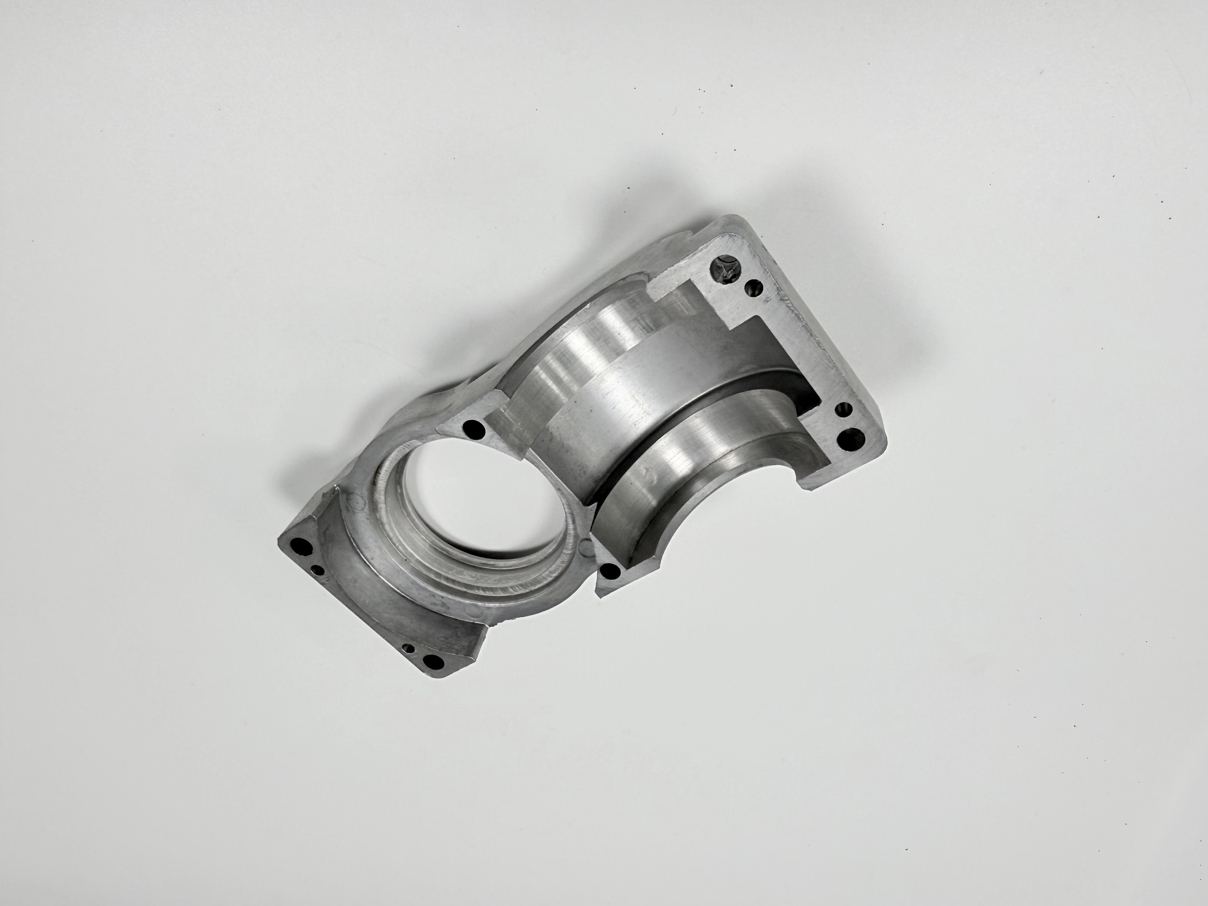
Record diameter, depth, steps, reliefs, entry chamfer, cross holes, interrupted arcs, bottom condition, and adjacent walls. Identify whether the bore is open or blind and whether a tool must pass through a split line or a thin section. Mark surfaces that control bearing, seal, guide, or clearance function. The split-housing views show circular seats and mounting holes, but they do not reveal dimensions, tolerances, material, or load; those come from the controlled drawing.
Use a sectioned model or coordinate list to check the path from tool holder to the deepest feature. Include clearance for approach, retract, measurement probe, chip removal, and cleaning. A nominal tool diameter can fit while its holder collides with a shoulder. Check the entire assembly orientation, not only the isolated CAD cavity. If a feature is blocked after assembly, decide whether it is machined before joining or verified by an alternate method.
Check Stiffness and Deflection Risk
Long reach increases sensitivity to holder projection, tool diameter, insert condition, cutting force, and support. State the maximum projection, holder type, tool material or grade where relevant, and the process signal used to detect deflection. Do not turn a catalog stiffness value into a finished-axis guarantee. The relationship between tool, material, stock distribution, and pass sequence determines the actual response.
Plan a measured trial pass when the bore is deep, interrupted, or thin-walled. Capture load trend, chatter, size drift, surface marks, and contact pattern, then inspect before continuing. A quiet cut does not prove a straight bore, and a good surface does not prove axis location. If a tool, holder, insert, or pass strategy changes, identify the affected CTQs and repeat the sensitive checks.
Control Chips and Coolant
Deep cavities can retain chips, recut debris, or abrasive particles. Define coolant direction, pressure or flow where controlled, chip evacuation, cleaning intervals, and the reaction to a blocked path. A trapped chip can shift seating or scratch a functional surface; a coolant stream can hide a change in cutting response. Record the condition at first piece and after any tool or program revision.
State whether the bore is measured wet, dry, washed, coated, or assembled. Residual coolant can affect contact, and cleaning can remove evidence of embedded debris. If an outside process follows boring, define the before-and-after checks and the state accepted by the buyer. A clean-looking cavity is not proof that all surfaces were reached or that the material was undamaged.
Match Fixture Access to Function
Fixture supports must hold the part without blocking the tool or distorting the datum. Define primary, secondary, and tertiary contacts, clamp direction, support under thin walls, and access windows. For a split housing, state whether both halves are bolted, doweled, or individually located. A fixture can be rigid and still misplace the functional axis if its contact sequence does not represent the drawing datum.
Check whether a flip or reorientation is required. Record witness features, orientation marks, and the transfer check after each setup. If a replacement locator, shim, or soft jaw is installed, treat it as a change until qualified. Do not infer access or support from an image; use the model, fixture drawing, and actual setup evidence.
Plan Inspection Reach Before Machining
An inaccessible region is a measurement decision, not merely a machining inconvenience. Identify probe length, bore-gauge reach, scan sections, calibration reference, and the alternate method for shoulders or bottoms. State what each method proves: size at sampled sections, form under a defined alignment, axis relationship, or functional fit. A plug or pin can indicate a condition at one state but cannot prove full form or location.
If inspection requires a destructive section, define the sample and the population it represents. If a correlation method is used, retain the correlation basis and limitations. Record unit identity, revision, temperature, restraint, cleaning, and instrument status. Hold release when the critical region is neither measured nor covered by an approved alternate method. Never mark an unmeasured depth as passing by averaging nearby readings.
React to Access or Cutting Failures
Contain the affected units when the holder contacts a shoulder, chips cannot evacuate, chatter appears, or the inspection tool cannot reach the specified region. Preserve the original setup and process data. Review collision clearance, projection, support, allowance, coolant, insert condition, and datum seating. Rework is possible only when enough stock and geometric margin remain and an authorized owner approves the route.
After a correction, repeat the measurements that could have been affected and identify the reworked units. A second successful pass does not erase a collision or an unknown surface history. If the access limitation cannot be solved, record the evidence boundary and obtain a drawing or acceptance decision rather than silently narrowing the scope.
Specify Access in the RFQ
Provide model sections, depth and diameter, steps, interruptions, entry and shoulder details, material condition, datum, fixture state, tool reach limits, coolant and chip requirements, inspection access, sampling, records, and change authority. Ask suppliers to show how the holder, tool, probe, and cleaning path reach every critical region. Request a redacted setup or inspection example that identifies inaccessible boundaries.
Require notification before changing tool projection, holder, insert, fixture, program, coolant, machine, inspection method, or material heat. Ask what process signal stops work and how the affected range is contained. A quote based on “deep-bore capability” without a feature map or evidence plan is not comparable with a scope that defines access and verification.
Buyer Action
Approve the route when full geometry access, stiffness, chip control, support, inspection reach, and failure reaction are documented for the actual bore. Hold it when a holder path is unverified, a deep region is inaccessible, or a machine specification is being used as product evidence. Deep-bore confidence comes from a checked path and a measured result with clear boundaries.