CNC Machining for Rapid Prototyping: Material, Design, and Inspection Decisions
CNC Machining for Rapid Prototyping: Material, Design, and Inspection Decisions
CNC machining for rapid prototyping works best when material, design intent, inspection timing, and revision control are planned around a specific learning decision. A prototype should reveal whether a feature can be reached, whether the chosen material behaves as expected, whether the part mates, or whether a test setup represents the intended use. It should not be described as production proof without a separate qualification path. A CNC prototyping workflow helps buyers connect those decisions before they request a quote.
Start With the Learning Decision
Write the question the prototype must answer: envelope clearance, tool access, assembly alignment, material response, surface interaction, load, motion, or inspection method. State the pass condition, evidence owner, and next action before cutting. A prototype can be successful even when it exposes a design failure, provided the failure is recorded and drives a controlled revision.
Separate exploratory features from released requirements. Temporary dimensions, hand-finished surfaces, shims, or substitute materials can be useful for learning but should not silently become production acceptance criteria. Mark what is provisional, what is controlled, and what remains open. This protects engineering and purchasing from interpreting a prototype quote as a final production specification.
Map Interfaces Before Geometry
Identify locating faces, clearance zones, threaded connections, moving joints, load paths, sealing boundaries, and cosmetic areas. For each interface, define datum, tolerance intent, measurement state, and functional check. A circular feature may be a pivot, a locating bore, or a visual detail; the picture cannot decide. The functional map should establish the consequence of drift and the method that detects it.
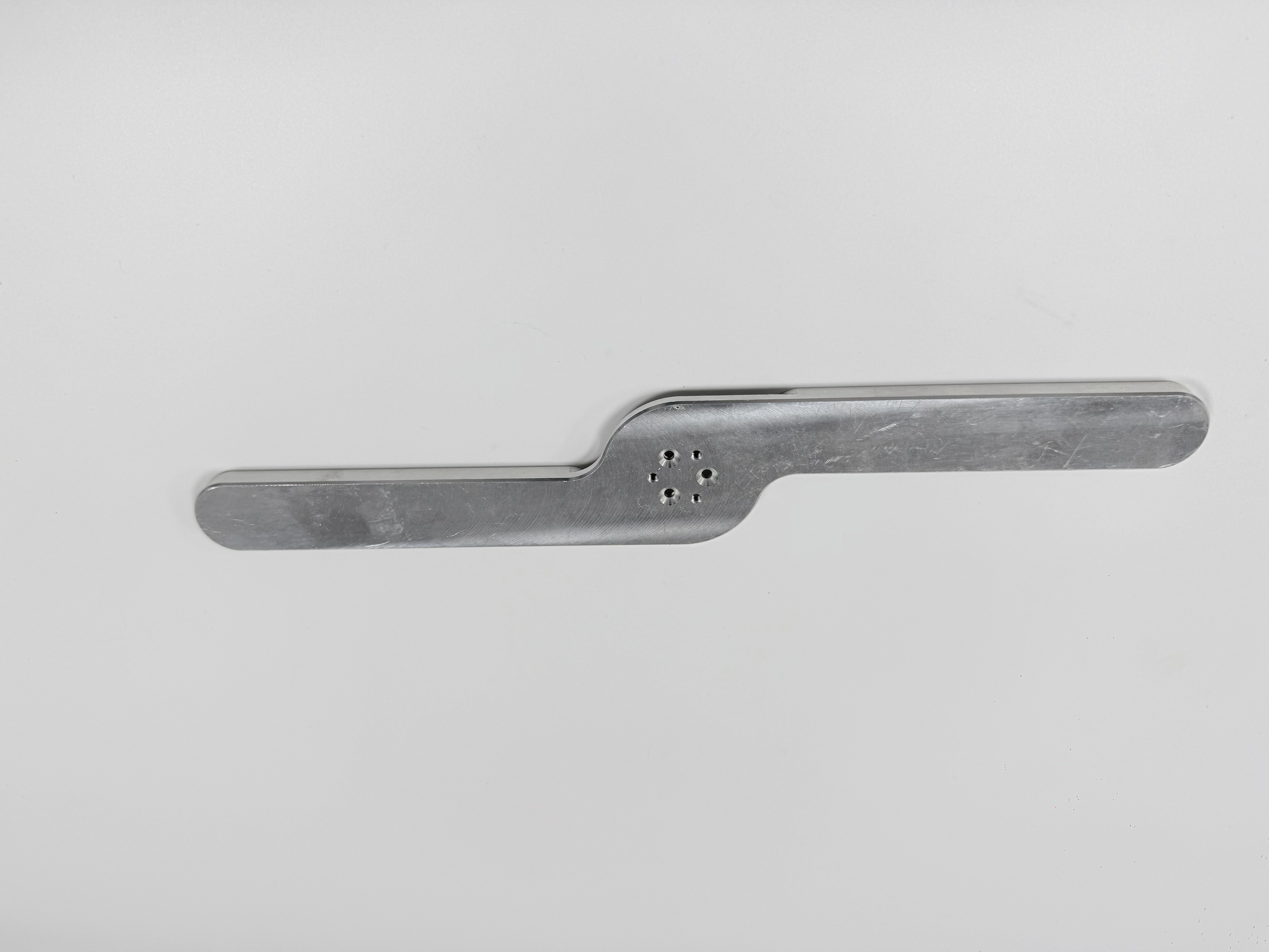
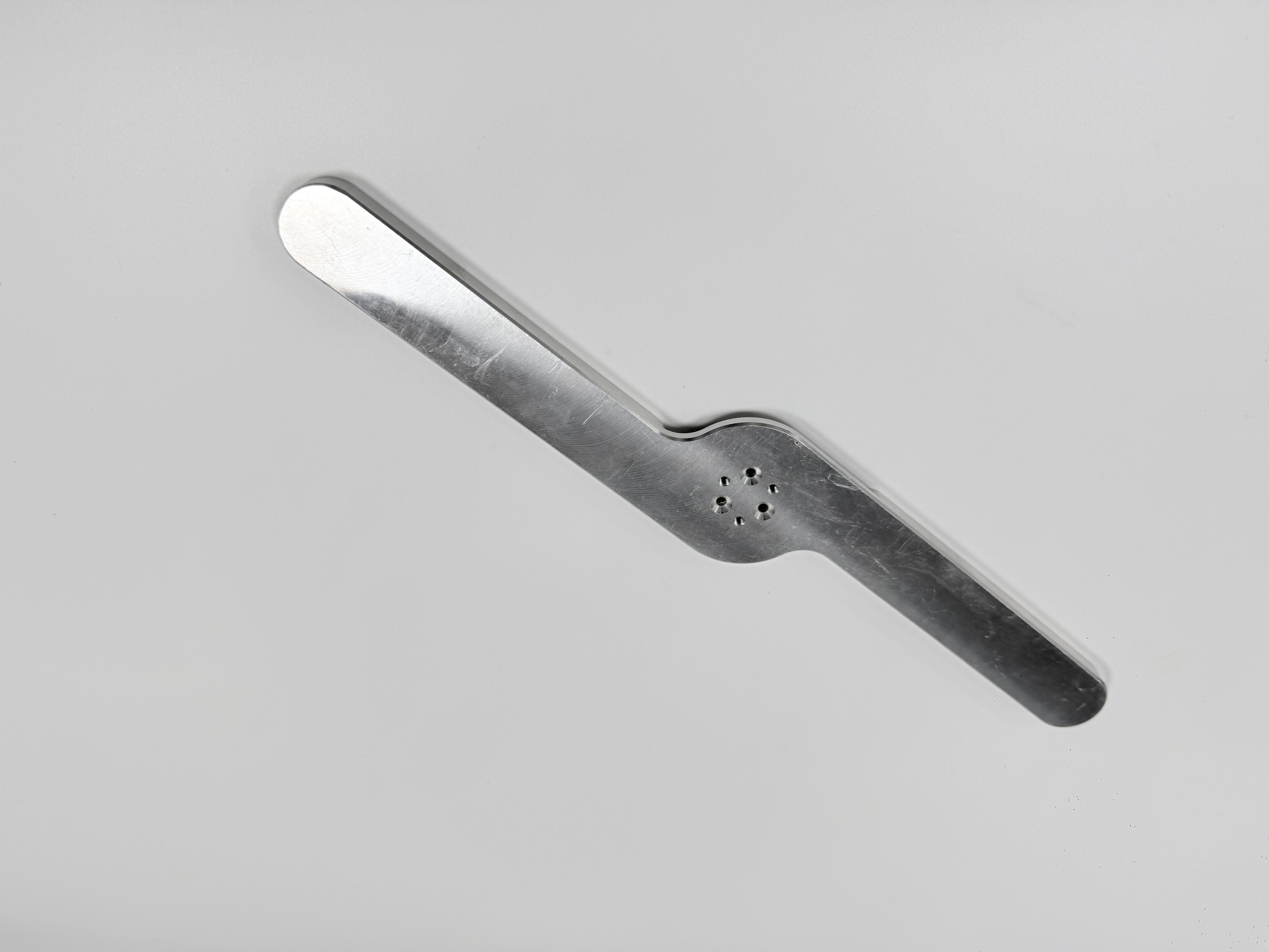
The paired matte link-arm images show a long body, recessed channels, a central circular region, and rounded ends. They confirm visible geometry and different views, but not material, strength, tolerance, application, or test outcome. Use the image to prompt questions about support and access; use the drawing and test plan to control the decision.
Choose Material for the Prototype Question
Material selection depends on what must be learned. Geometry and access may allow an approved representative alloy or polymer, while wear, heat, corrosion, electrical contact, sealing, or load questions may require the production designation and condition. Record stock source, heat or lot, certificate scope, and any deliberate substitution. Do not infer material from color, finish, or image.
A material certificate supports identity within its stated scope; it does not prove finished geometry, hardness after processing, roughness, or function. If a substitute material is used, list which conclusions transfer and which require a production-material build. If heat treatment, coating, cleaning, or aging is included, record the state and before-and-after evidence.
State Material Boundaries
Material condition can affect tool wear, burrs, distortion, friction, and test response. A controlled aluminum machining reference or stainless-steel machining reference can frame questions about heat and work hardening, but the approved drawing controls grade and condition.
Design Prototype Features for Reachable Evidence
Design review should consider tool diameter, approach angle, holder clearance, chip evacuation, workholding, and probe or gauge access. A feature that can be modeled may be difficult to machine or inspect in the selected orientation. Mark deep pockets, narrow channels, cross holes, thin walls, and internal corners that may require alternate tools or a second setup.
Access decisions should be linked to function. If a recessed channel is a clearance path, define the mating envelope and burr limit. If it is cosmetic, define appearance separately. If a central circular feature locates another part, define datum and position evidence. Avoid claiming that a five-axis, turning, boring, or grinding route is needed until the characteristic and access reason are documented.
Plan Fixture Access
Document contact order, support, clamp direction, datum transfer, and measurement state. A prototype fixture may prove access without being suitable for repeat production. If clamping can deflect a thin feature, measure free and restrained states when both matter. If the test uses an assembly fixture, identify the mating hardware and load condition.
Set Tolerance Intent and Inspection Timing
Classify dimensions as functional CTQs, references, cosmetic controls, or open learning variables. State datum, nominal or limit, units, method, instrument, and state. A CMM result reports within a defined alignment; a gauge can demonstrate fit; a visual check can identify a burr. None should be described as proving a different characteristic.
Inspection timing should match the learning cycle. Verify the first unit before cutting a full prototype set when a setup or program could be wrong. Inspect after a material or fixture change. Measure before and after coating or heat treatment when the delivered state matters. Keep raw and corrected results linked to the prototype revision.
Separate Dimensional and Functional Evidence
| Evidence | Supports | Limit |
|---|---|---|
| Dimensional result | Feature in stated datum and state | Not load, sealing, or motion |
| Fit check | Specified mating engagement | Not every location or form |
| Functional test | Defined load, motion, or cycle | Not production repeatability |
| Visual review | Visible surface or burr condition | Not hidden material or geometry |
The table keeps evidence bounded. A quality inspection planning reference can organize ownership, but the prototype question defines the acceptance evidence.
Plan Functional Testing Around the Assembly
Define mating hardware, load direction, temperature, fluid, cycle, travel, speed, support, and pass/fail rule. Identify instrument, units, sample, and environment. If the prototype uses a temporary fixture or hand adjustment, record it. A successful test validates the stated condition; it does not establish untested service life, production capacity, or a different material.
Anticipate failure modes: interference, looseness, burr capture, distortion after unclamping, fastener mismatch, surface damage, or loss of alignment. State containment, rework, repeat-test, and revision decisions. Preserve failed units and raw observations when they help identify cause.
Check Test Repeatability
If the question depends on repeat placement, run the stated number of cycles and record fixture configuration, operator steps, and reset method. If the result changes after reassembly, identify whether the cause is part, fixture, hardware, or procedure. Do not average incompatible conditions. Document the boundary before interpreting a trend.
Control Revisions From CAD to Test
Use one identifier across drawing, model, CAM reference, setup sheet, material record, fixture, inspection template, test report, and package label. Isolate units made before and after a change. Record old and new values, effective date, reason, affected CTQs, owner, approval, and evidence. Never edit an old report to represent a new geometry.
Classify changes as design, process, material, fixture, tooling, inspection, test, outside processing, or packaging. A new hole position may require a new prototype; a fixture change may require a repeat test; a material change may invalidate a durability conclusion. If an urgent change is approved, define containment and expiry.
Carry Open Actions Forward
List open issue, evidence needed, owner, due revision, and decision rule. If a CTQ was not measured because access was unavailable, record the gap rather than marking it accepted. Close an action only when evidence exists or an authorized decision accepts the limitation.
Compare Route Options Without Overclaiming
Compare milling, turning, boring, grinding, probing, manual finishing, and outside processing by the characteristics they control and the evidence they produce. Fewer operations are not automatically better if they obscure datum transfer or inspection. Ask how each route handles thin walls, deep features, burrs, surface state, and reorientation.
Use a CNC milling route, turning route, or boring route as planning references only. The service page does not prove the prototype's material, tolerance, or function. Require a part-specific route explanation and evidence plan. When a prototype must scale beyond a one-off build, a low-volume manufacturing review can frame repeatability questions. A mass-production planning reference can frame a later handoff. These links organize planning only; they do not prove capability for the pictured part.
When access is uncertain, ask the supplier to identify the tool approach, holder envelope, setup orientation, and inspection path before cutting. A route can reach a pocket with a cutter yet fail to clean chips, measure the bottom, or maintain a datum after reorientation. Record the access assumption and the evidence that will confirm it. If the feature is not measurable in the proposed state, treat that as a design or process decision rather than hiding it in a later inspection note.
Manage Chips, Burrs, and Edge Risk
Prototype channels and cross features can retain chips or develop burrs that alter fit. Define cleaning, deburring, edge break, and visual acceptance before the functional test. If hand deburring is allowed for learning, record where it occurred and whether the result transfers to production. A smooth-looking surface does not prove that an interface is free of burrs or that a dimensional requirement is met.
Ask the supplier to identify burr-sensitive features and the method used to inspect them. A visual check may detect a visible edge condition; it does not establish a hidden bore size or positional relationship. If a mating test fails, separate geometry, burr, contamination, and fixture causes before revising the design.
Choose Operation Order for Clear Learning
Operation order affects which prototype result can be interpreted. Establishing a datum before machining a critical pattern may be necessary for a location question; leaving a finishing pass until after a fit trial may reveal whether stock or burrs are the cause. Document roughing, semi-finishing, finishing, deburring, cleaning, and inspection sequence. Avoid adding a secondary operation only because it sounds more precise; tie it to a characteristic and evidence.
If a secondary process changes the state, define its boundary. Grinding can change surface texture and datum, coating can change mating dimensions, and heat treatment can change distortion. A grinding route or coating reference can frame planning questions, but the prototype test defines what is accepted. A quality inspection reference can help assign post-process checks.
Use the First Piece to Test the Route
Inspect the first unit before making the full prototype set when a setup, tool, or datum transfer could invalidate the learning. Confirm revision, material, fixture, program, offsets, and measurement state. If the first unit is adjusted, preserve the original result, reason, and confirming check. This separates a controlled correction from an undocumented process change.
Measure at the Right Time
Inspection timing should answer the prototype question while keeping the state visible. Measure before and after operations that can move a feature. Check a thin wall supported and free when both states matter. Measure a coated or heat-treated interface after that process if the delivered condition is being evaluated. Record temperature, support, fixture, instrument, units, and sample identity.
Do not combine results from different states or revisions. A CMM result reports a characteristic in its alignment; a gauge demonstrates a defined fit; a functional test validates the stated condition. Each has a boundary. If a result is missing or invalid, hold the decision and define a repeat or disposition.
Keep Raw Data With the Summary
A signed summary should point to raw measurement data, test readings, fixture checks, material records, photographs, deviations, and rework history. Preserve the original value when a correction or offset is made. The raw record may explain a design decision months later when a prototype is compared with production. A conclusion without source data is difficult to transfer.
Review Prototype Risk Before a Production Claim
At the end of the build, review design, material, process, fixture, tooling, inspection, test, and logistics risks separately. Identify what failed, what passed under a stated condition, what was not measured, and what remains open. Do not convert a successful appearance review into a capability statement. A prototype can reduce uncertainty while still requiring a production-material build, a capability study, or a revised test fixture.
Use a risk review that assigns an owner and due revision. If the risk cannot be closed safely with the current prototype, state the evidence needed. Examples include a repeat test with production material, an assembled check after coating, a free-state measurement, or a new fixture qualification. This keeps the handoff honest and actionable.
Use a Risk Review Table
| Risk | Question | Next evidence |
|---|---|---|
| Access | Can the feature be made and inspected? | Tool/fixture review and CTQ result |
| Material | Does the state represent the test? | Certificate and representative build |
| Function | Does the defined condition pass? | Raw test data and mating record |
| Transfer | What enters production control? | Signed transfer and open actions |
The table is a risk aid, not a release certificate. Keep the prototype limitation beside the evidence so a later buyer does not infer a broader claim.
Review Supplier Feedback as Evidence
Supplier feedback should explain manufacturability, access, datum, material, fixture, inspection, and test limits for the actual revision. A generic design-for-machining note is less useful than a characteristic-specific observation with a proposed change and verification. Ask whether the recommendation affects function, cost, lead time, or only convenience.
Compare responses by evidence and ownership. A credible supplier identifies what can be made as drawn, what needs a controlled change, what is not measurable in the proposed state, and what test support is included. Do not accept a machine list or broad prototype claim as proof.
Release the Prototype Decision
Release when objective, revision, material, fixture, process, test state, dimensional evidence, functional result, open actions, and approval agree. Hold when an inaccessible CTQ, uncontrolled substitution, undefined state, or missing record remains. A prototype may be technically useful without being production-ready when the limitation and next action are explicit.
The strongest CNC machining rapid prototyping plan turns every build into controlled learning. Define the question, choose material for it, design reachable features and fixtures, set tolerance intent, inspect at meaningful times, preserve raw evidence, control revisions, and transfer only approved learning. Use the pictured link arm as a geometry prompt; let the controlled documents and test records govern the next build.
Write an RFQ That Makes Learning Comparable
Attach drawing and model revision, prototype objective, material and condition, tolerance intent, CTQs, access constraints, fixture or test method, finish, quantity, records, and milestones. Ask suppliers to identify route, setup, tool access, measurement, functional testing, and known limitations. Separate prototype engineering, fixture, and test costs from recurring production conversion.
Request raw data, signed summaries, material certificates, fixture descriptions, test records, and change logs in the required format. Ask what assumptions remain unvalidated and what event reopens qualification. Require notification before material, tool, fixture, program, route, processor, inspection, packaging, or ownership changes.
Screen Suppliers on Prototype Evidence
Compare whether each candidate explains material control, design-for-machining feedback, datum and fixture strategy, inspection state, test support, revision traceability, and production boundary. A machine list or generic prototype claim is not proof. Ask for an anonymized route or report format tied to comparable geometry.
Choose the response that names unknowns, owners, evidence, and approval points. A credible supplier states what is measured, tested, sampled, or deferred. It does not turn a photograph, one fit check, or one prototype result into a universal capability claim.
Handoff Only Approved Learning
Classify observations as released requirement, production control, design learning, or non-transferable evidence. A fixture access lesson may become a setup rule; a hand-polished surface may not become a production finish; a fit result with production material may support a later build but does not prove lot capability. Require an engineering decision for every transfer.
Define production first-piece, CTQ inspection, functional evidence, outside-process records, packaging, and change triggers. Include a not-transferred list for temporary dimensions, substitute materials, exploratory fixtures, and untested conditions. The handoff is complete only when the approved route and records describe the same configuration.
Release a Prototype Decision With Boundaries
Release when objective, revision, material, fixture, test state, dimensional evidence, functional result, open actions, and approval agree. Hold or repeat when a result uses the wrong revision, uncontrolled material, undefined test state, or inaccessible CTQ. A prototype may be useful without being production-ready when its limits are explicit.
The strongest CNC machining rapid prototyping decision turns each build into controlled learning. Define the question, select material for it, design reachable features and fixtures, set tolerance intent, separate dimensional and functional evidence, control revisions, and transfer only approved learning. Use the pictured link arm as a geometry prompt; let the controlled documents and test records govern the next build.
FAQ