
Datum Transfer in CNC Turning of Impellers and Wear Rings
Datum Transfer in CNC Turning of Impellers and Wear Rings
Datum transfer is the disciplined handover of a functional reference from one setup or component state to the next. A closed impeller body and its associated wear rings provide a useful example because circular faces, bores, seats, and mating interfaces may be accessed at different times. In impeller machining datum transfer, the central question is how the intended axis and axial reference will be reproduced, not simply which surface is easiest to grip. Applied to an industrial equipment component, this reference logic keeps each setup focused on the relationships required by the next state.
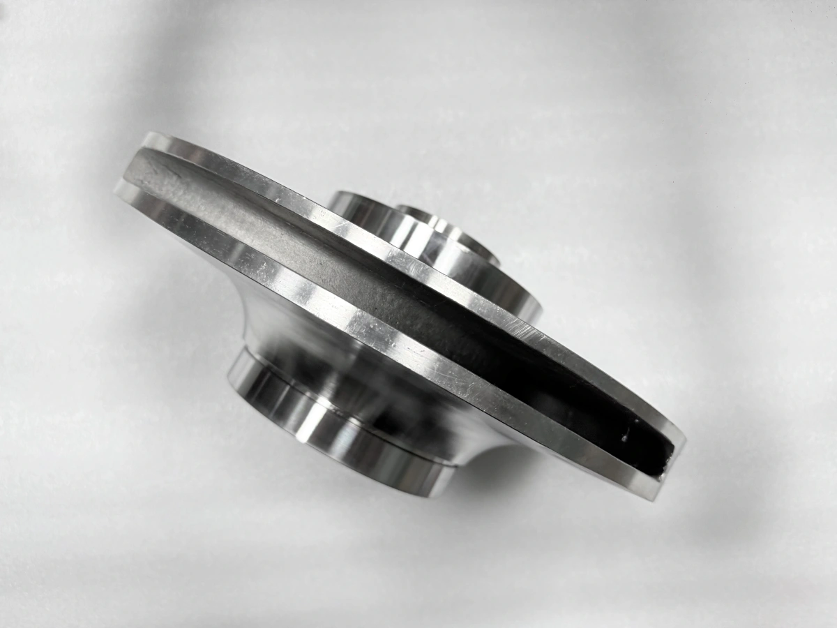
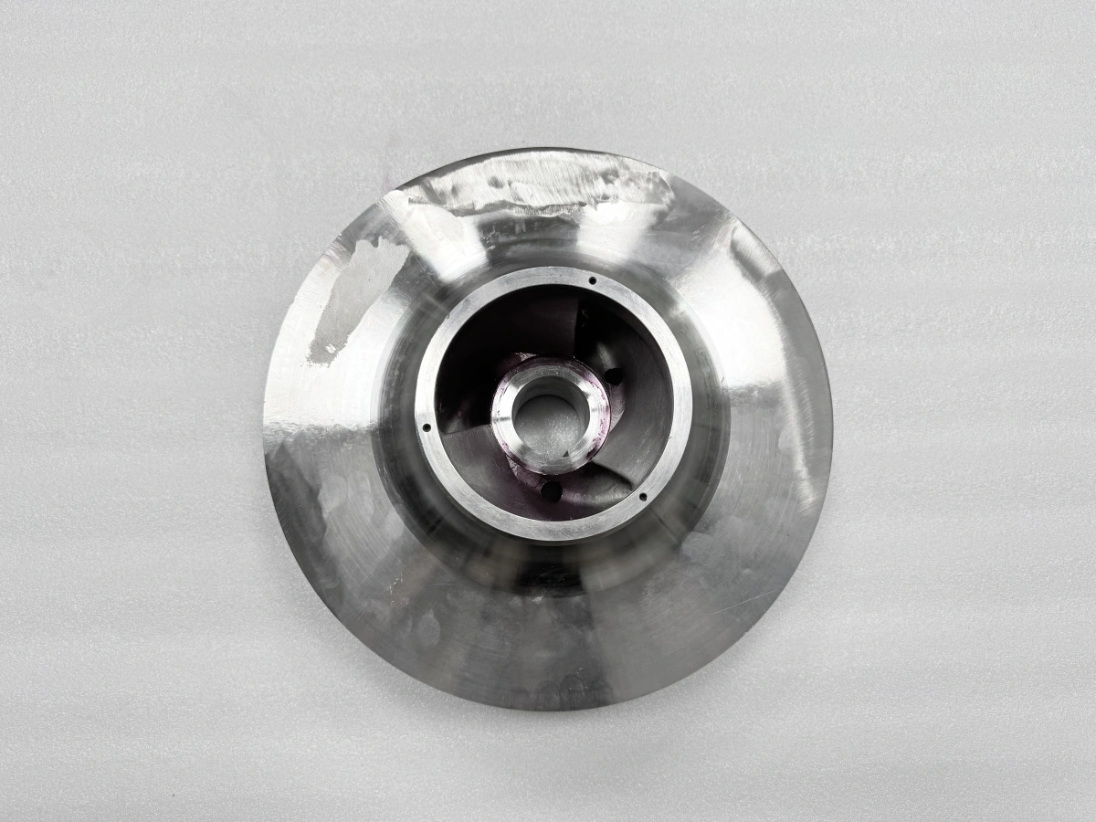
Define the Datum by Function, Not Convenience
A datum is an exact reference derived from a selected feature; the shop setup only creates a practical simulator for that reference. On a rotational component, the functional scheme may combine an axis from a cylindrical feature, an axial plane from a face, and a separate feature for angular orientation. The broad cast surface that appears easiest to hold does not automatically control any of those relationships. Selection begins with the released interface requirements and the state in which those requirements apply.
This distinction matters in precision machining because a design datum, a setup locator, and an inspection reference can be physically different while still representing the same intended relationship. A useful datum map names each role and shows how it connects to the next operation. It also identifies where the chain could be broken by using an unqualified raw surface, changing the component state, or measuring from a convenient feature that is not functionally related.
Give Locators, Supports, and Clamps Separate Jobs
Locating, supporting, and clamping are related but not interchangeable. Locators establish position and constrain the intended degrees of freedom. Supports resist cutting load or help a broad feature remain stable without redefining the reference. Clamps maintain contact against the locators. When one element is expected to do all three jobs, small seating changes can become reference changes, and a reading taken under load may describe the fixture condition more than the relaxed component.
A sound CNC turning workholding review therefore labels the contacts before discussing force. The turned-part axis and workholding plan should make clear which contacts establish the axis, which establish the axial position, and which only add stability. This division does not prescribe one fixture design. It provides a test: removing or adjusting a support should not silently replace the approved locator, while clamping should not pull the part away from its defined seating condition.
Create a Recoverable Reference Before Reorientation
A setup reversal changes access, so the first orientation should leave a reference that the next orientation can recover. That reference might be a qualified cylindrical feature paired with a face, provided the drawing relationship and remaining stock support that choice. Broader CNC machining may create other secondary features, but they should enter the datum chain only when their purpose is defined. Visual symmetry or a convenient outside edge is not enough.
Recovery also needs more than a diameter. A cylindrical reference can re-establish an axis, yet it cannot by itself fix axial position. A face can establish axial location, yet it does not necessarily control angular orientation. If clocking matters, the plan identifies a separate feature and states when it becomes usable. Treating the transfer as a combined axis-plane-orientation relationship makes setup intent readable and helps prevent a later feature from acquiring an unintended datum role merely because it remains accessible.
Track the Direction of Error at Each Handover
Every transfer can introduce a different kind of displacement. Radial seating variation can shift an axis; uneven axial contact can tilt it; debris or inconsistent support can move a plane; clamp load can change the observed shape. A datum-transfer review follows these directions rather than combining them into one general accuracy statement. It asks which interface can influence the next one, which stock remains available for correction, and whether the inspection reference represents the same component state as the machining reference.
A consistent quality assurance approach supports the datum chain by preserving the context of each observation. A useful record identifies the referenced axis or plane, the setup or assembly state, and the feature being related to it. That information lets engineering compare observations made before and after a handover without assuming they are interchangeable. Each check then answers a defined relationship at a defined state instead of being read outside the setup that gave it meaning.
Keep Wear Rings Inside the Assembly Datum Chain
Wear ring concentricity is not only a property of an isolated ring. The engineering question is how the ring's working surface relates to its locating interface, how that interface relates to the impeller reference, and which component state governs the released requirement. A ring measured free, seated for evaluation, or considered with an assembled impeller may present different reference conditions. The route should name the controlling state instead of transferring a free-part assumption into an assembly requirement.
When a bore or seat must be related to a rotational reference, CNC boring can be considered as one method of establishing that relationship. Assembly finish-machining may also be considered when the released interface is defined in the assembled state. The drawing, accessible geometry, remaining allowance, recoverable datum, and assembly condition determine whether either method belongs in the route.
Match Workholding to the Active Component State
The active datum can change as the component moves from an initial reference setup to a reversed setup or an assembly-related evaluation. Workholding should follow that change deliberately. A locator used early to create a stable machining reference may become unsuitable after the functional bore and face are available. Conversely, a newly finished surface should not be treated as a locator if its relationship to the controlling datum has not been established.
Support strategy changes with the state as well. A broad shroud may need stability against machining load, while the hub and selected faces carry the reference logic. The plan separates support contact from datum contact and states whether evaluation occurs while clamped, after release, or in another defined condition. That wording prevents a fixture-induced condition from being mistaken for a component relationship and keeps the reference chain understandable across handoffs.
Scale the Datum Map for a Small Batch
In low-volume manufacturing, a concise datum map is often more valuable than a large generic procedure. It can show the functional datum, the simulator used in each setup, the transfer feature, the locator-support-clamp roles, the component state, and the related verification point. This gives each setup a common engineering language without implying that every visible surface needs the same level of control.
The map should also mark decision points. If a reference feature does not clean up as expected, if a support becomes a locator, or if the assembled state changes the relevant relationship, the route returns to engineering review before final stock is consumed. That preserves the intent of the datum chain when a small batch does not justify learning the same lesson twice.
Review the Chain Before Releasing the Turning Scope
Before releasing CNC turning, trace one line from the functional interface to the datum feature, setup simulator, transfer reference, component state, and verification reference. Repeat that trace for the impeller body and each associated wear-ring relationship. Neway can use the current impeller and mating-component drawings to review where the axis and axial plane originate, how they remain recoverable after reorientation, and whether any assembly-state relationship calls for a conditional finishing decision.
FAQ
