How Should a Turned-Part Axis and Workholding Plan Be Set?
How Should a Turned-Part Axis and Workholding Plan Be Set?
A turned-part axis and workholding plan should be set from the functional datum, stock condition, chuck or collet contact, support needs, and the final measurement state. A chuck can hold a component securely while the functional axis is still shifted by jaws, burrs, runout, or an incorrect reference surface. The buyer should define the axis relationships and require a setup verification on the actual part before production turning.
Identify the Functional Axis
State whether the axis controls a bearing, seal, shaft, nozzle passage, thread, flange, or face-hole pattern. Separate diameter, roundness, cylindricity, runout, concentricity, perpendicularity, and location. A diameter measured at one point cannot prove those relationships. Include mating hardware, load, temperature, lubricant, and assembly sequence when they change the decision.
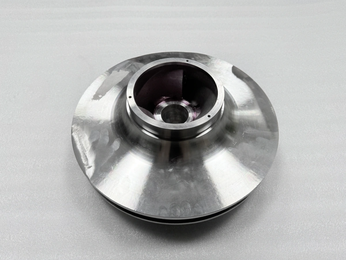
The paired images show one turned cylindrical nozzle-like part with a flange, central opening, grooves, stepped diameters, and small face holes from two angles. They confirm visible geometry and a different view only. They do not reveal material, thread class, pressure, tolerance, or application. Use the controlled drawing to establish the axis.
Check Stock and Seating
Record raw or semi-finished diameter, straightness, wall thickness, scale, coating, burrs, and damage. State jaw or collet engagement, contact length, shoulder seating, and tailstock or steady-rest support. A burr under a jaw can create apparent runout; a short engagement can amplify deflection. Clean and inspect the contact before loading and record the condition.
Define an entry window for critical surfaces. Too little material can leave a damaged layer or prior runout; too much can increase force and cycle time. Link the entry measurement to unit identity, material heat, revision, fixture, and operator or owner. A certificate supports material identity within scope; it does not prove straightness or seating.
Control Contact and Clamp Sequence
Name primary, secondary, and tertiary contacts and state which is established first. Record chuck type, jaw set, soft-jaw bore, collet, support, clamp force where controlled, and orientation. If a component is reversed, identify the witness face or diameter that transfers the axis. A second setup needs its own check; it does not inherit the first setup automatically.
For a flange and bore, decide whether the flange face, outer diameter, or internal axis is the functional reference. A convenient outer surface may not represent the assembly datum. If face holes are used, define clocking from a key or datum feature. Record support revisions.
Verify the Setup on the Part
Run a setup check with a witness diameter, face, or bore tied to the functional axis. Record runout, contact, temperature, instrument, unit identity, and result. A machine coordinate or chuck repeatability statement is not product evidence. If the check fails, hold the part and investigate chips, jaw wear, clamping, stock, and datum interpretation.
After a flip, jaw, collet, support, machine, or program change, repeat sensitive characteristics. Preserve the failed result and affected unit range. Re-turning may consume allowance or change a shoulder relationship, so an owner must approve rework and define checks to repeat.
Support Slender and Thin Geometry
Slender shafts, thin walls, deep bores, and interrupted flange cuts can deflect under tool or clamp force. State length-to-diameter risk, tool projection, steady rest, tailstock, boring bar support, cutting direction, and process signals. A quiet cut does not prove runout or concentricity. Use a measured trial and inspect before committing to the full lot when stiffness is uncertain.
Control chip evacuation and coolant so debris cannot shift seating or scratch a seal. If the component is cleaned, coated, or assembled after turning, define the state in which fit and axis are accepted. Keep as-turned and delivered-state records separate.
Measure Axis-Related Characteristics Separately
Use a micrometer or bore gauge for defined size locations, an indicator or scan for runout, and a datum-framed method for position or coaxiality. A thread gauge shows fit under its own condition and does not prove shoulder location. A functional assembly check adds behavior evidence but cannot replace unmeasured geometry. State sections, angles, depths, support, temperature, units, and calibration.
For a stepped nozzle, measure the bore, shoulder, flange face, grooves, and bolt-hole clocking separately, then evaluate their relationships in the common frame. If a probe cannot access a region, document the boundary and alternate method.
Control Material and Thermal State
Material designation, temper, hardness, bar condition, heat treatment, and stress relief affect cutting force and movement. Record the state before turning and any stabilization. Do not infer alloy or hardness from the image. If a substitution is proposed, name which conclusions transfer.
State part temperature, room temperature, coolant removal, cleaning, storage, and measurement timing. A warm or contaminated part can report a different fit than a stabilized one. If outside processing follows turning, record processor, batch, specification, before-and-after checks, and delivered state.
React to Workholding Failure
Contain the unit when runout rises, a jaw mark appears, a support moves, chatter begins, or the part shifts after unclamping. Preserve setup, tool, stock, datum, and measurement records. Review jaw condition, seating, clamp force, support, projection, and temperature. Do not polish away a mark or overwrite the original reading.
If rework is possible, confirm remaining stock, axis margin, shoulder location, and all affected CTQs. If the affected range cannot be bounded, expand inspection or obtain an approved deviation. Release only after the acceptance owner confirms the required state.
Specify Workholding in the RFQ
Provide drawing and model revisions, functional axis, stock, material, jaw or collet limits, support, reverse setup, witness features, temperature, inspection, sampling, records, and change authority. Ask suppliers to state engagement, seating checks, support, tool projection, runout verification, and reactions to jaw, collet, support, or program changes.
Request a redacted setup format showing unit identity, contact sequence, runout, and revision. A quote that lists only a diameter and cycle time is incomplete when workholding controls the axis.
Buyer Action
Approve the plan when functional axis, contacts, support, stock, transfer checks, separate measurements, and failure reactions are explicit. Hold it when the chuck is treated as proof, a second setup is unverified, or the delivered state is unknown. A defensible lathe setup is repeatable on the actual part and tied to the drawing datum.