CNC Machining Prototyping vs 3D Printing: When Precision Prototype Parts Need CNC
CNC Machining Prototyping vs 3D Printing: When Precision Prototype Parts Need CNC
Choose CNC machining when a precision prototype must prove production-relevant material behavior, datum-related dimensions, assembly fit, threads, sealing contact, loaded interfaces, or the final surface state. Choose CNC machining prototyping for those evidence needs, and use 3D printing services when the next decision concerns shape, packaging space, ergonomics, rapid geometry iteration, or an internal form that machining cannot economically reveal at the concept stage. Neither route is automatically more accurate, faster, or less expensive for every prototype. The useful comparison is whether the material, process history, feature access, and inspection state represent the question being tested.
A process decision should begin with a written test claim: what must the prototype demonstrate, which failure would reject the design, and what evidence will release the next stage? A printed model can answer whether a housing envelope clears neighboring parts without consuming production-intent stock. A machined sample can test a specified bore-to-datum relationship, a threaded insert load path, or a seal land in the required material state. If one sample cannot answer both classes of question, sequence them rather than forcing one process to imitate the other. This evidence-led approach makes prototyping services useful as controlled learning steps instead of miniature production runs.
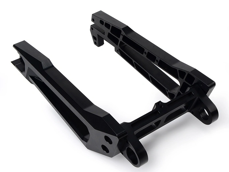
CNC and 3D Printing Solve Different Prototype Problems
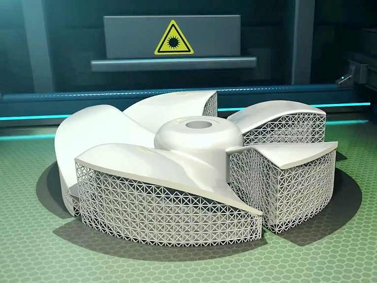
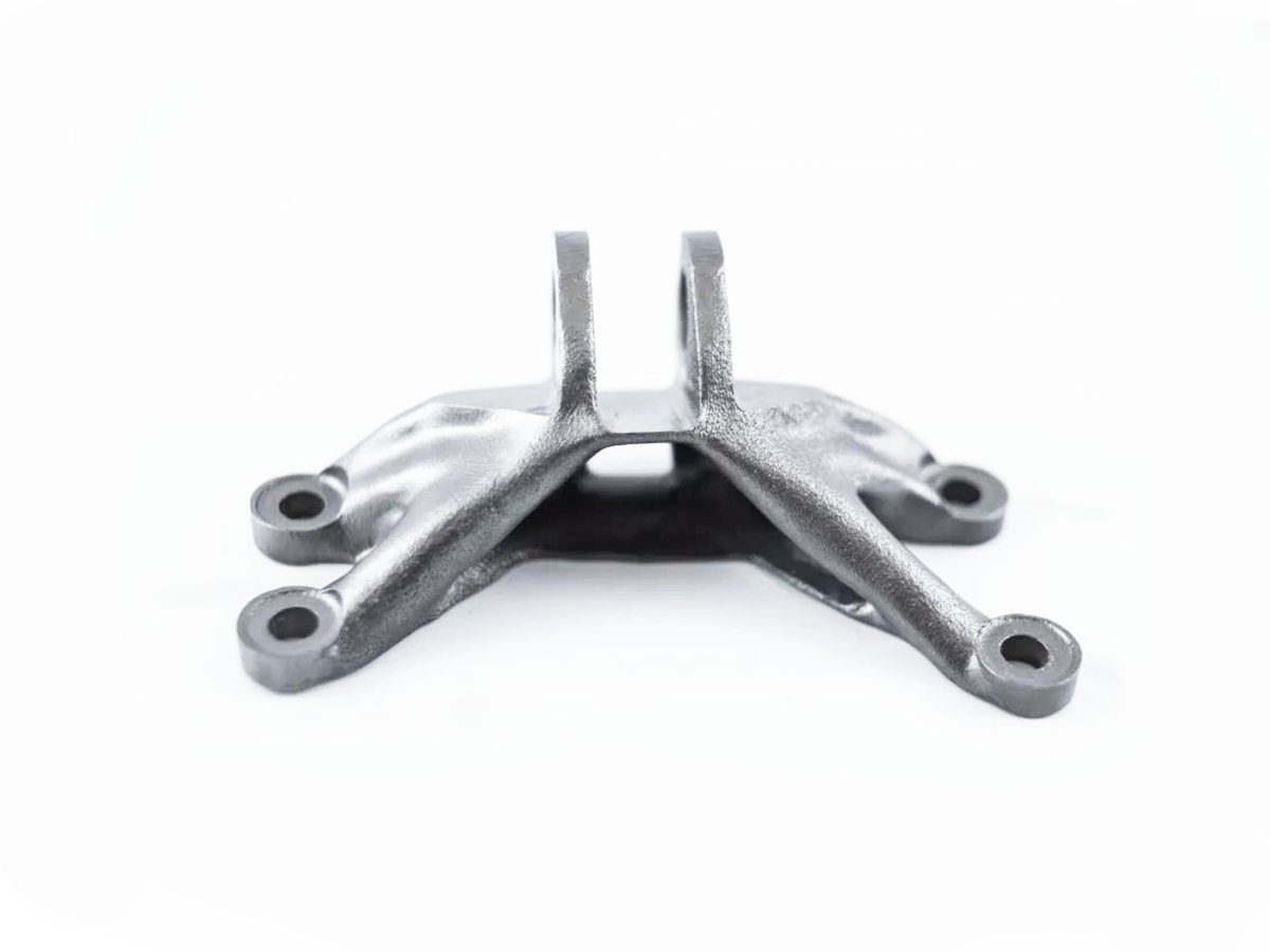
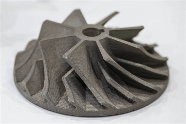
CNC machining and 3D printing create different evidence because they form material differently. Additive processes build geometry layer by layer, so build orientation, support removal, thermal history, infill or scan strategy, and post-processing can affect the result. That route is valuable when design risk is concentrated in external form, assembly space, human interaction, routing, or complex passages. A printed model can expose interference and access problems early, but its material and surface condition must not be assumed to reproduce a later machined component. The engineering team should record which observations are geometric and which would change with production material or process history.
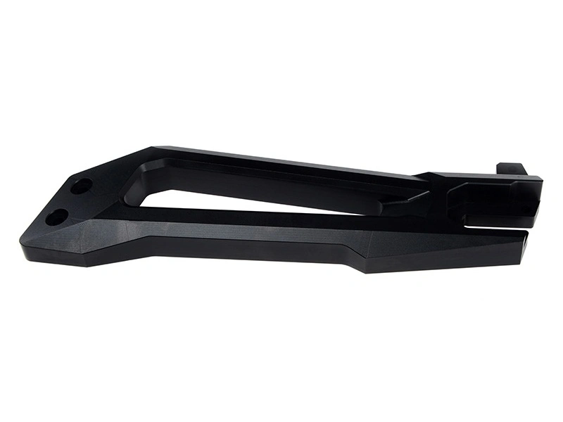
CNC removes material from stock through defined setups, tools, and cutting paths. It can preserve production-relevant alloy or polymer identity and can create datums, bores, threads, grooves, and contact faces using a route closer to later machining. Its limits are equally important: tool access, fixturing, stock condition, residual stress, cutter deflection, burr formation, and release from the fixture can change the measured part. A machined prototype therefore needs a drawing, setup logic, and inspection plan rather than a generic claim of precision. The linked CNC machining vs 3D printing comparison addresses the broader process choice; this page narrows the decision to evidence required from precision prototype parts.
When CNC Machining Is Better for Prototype Parts
CNC machining is the stronger prototype route when rejection or release depends on a production-relevant material, a controlled datum scheme, or functional interfaces that must be cut and inspected in their final relationship. Examples include a bearing bore located from mounting datums, a metal thread carrying preload, a seal groove evaluated with its mating hardware, or a thin wall measured after unclamping. The buyer should specify the feature relationship and acceptance method, not merely request a tight general tolerance. Material identity alone is insufficient. Wrought plate, extrusion, bar, casting, and molded polymer can carry different grain flow, residual stress, stock allowance, or anisotropy even when their nominal grade matches. A prototype intended to validate distortion or load transfer should therefore use the relevant grade, condition, and stock form, or the test limitation must be stated. A hypothetical valve housing illustrates the boundary: a printed shell may confirm port access and envelope, while a machined housing is needed before approving bore alignment, thread engagement, sealing contact, and pressure-test preparation in the selected material state. The drawing should also distinguish functional characteristics from dimensions included only to define geometry. That distinction lets inspection effort follow risk instead of treating every feature as an equal release condition.
Evidence the Prototype Must Produce | Why CNC Machining Is the Relevant Route |
|---|---|
Production-relevant material response | Uses the specified alloy, polymer, temper, heat-treatment state, and stock form when those variables control stiffness, thread behavior, wear, or test loading. |
Datum-controlled assembly fit | Creates mating bores, faces, and locating features through planned setups, then verifies their stated relationship from the drawing datums after fixture release. |
Threads and sealing interfaces | Cuts the specified thread, groove, land, and contact surface so engagement, compression, leakage risk, burrs, and edge condition can be evaluated with mating hardware. |
Final surface state | Supports inspection after the named machining, deburring, coating, grinding, or polishing state because each later operation can change dimensions and contact behavior. |
Functional load-path validation | Preserves material continuity and production-like interfaces where a test load, clamp force, bearing reaction, or fastener preload must travel through the actual geometry. |
Repeatable low-volume process evidence | Records setups, tools, datums, in-process checks, and finishing allowances that can inform a controlled transition into low-volume manufacturing |
A CNC prototype is not accepted because the machine can position precisely; acceptance comes from measured features in the required part state. The supplier workflow should connect stock verification, roughing, stress-relief decisions where specified, datum preparation, finishing, deburring, surface treatment, and inspection. Measurements taken before coating or before a thin part is released may not describe the delivered interface. A thin bracket can meet an in-fixture profile yet move after clamp force is removed, while an anodized bore can differ from its pre-treatment size. The control plan should identify when the part is allowed to stabilize, which surfaces establish measurement, and whether mating components participate in verification. Tool wear and burr formation also matter when a thread lead, sealing edge, or small cross-hole defines the test. Inspection should target the resulting failure mode through a suitable gauge, CMM strategy, surface measurement, assembly check, or functional test. For parts governed by feature relationships, the drawing should identify datums, toleranced characteristics, material state, and inspection conditions. A dimensional report should name the drawing revision and part state so later teams do not compare unlike evidence. That discipline aligns prototype evidence with precision machining without claiming that a prototype process alone guarantees the final result.
When 3D Printing May Be the Better Prototype Process
3D printing is the better first route when the project must learn about geometry faster than it must learn about production material or machined feature relationships. Suitable questions include whether an enclosure fits its allocated volume, a handle supports the intended posture, a cable route has clearance, a manifold concept connects the right ports, or several external forms deserve comparison. Additive fabrication can also reveal internal channels or consolidated shapes that would require split parts or inaccessible tooling in a machined model. A design review can mark contact, interference, inaccessible fasteners, trapped volume, and routing conflicts directly on the printed sample. The team can then compare those observations with the controlled CAD revision rather than debating a screen image. For a fluid passage, a transparent or sectioned model may support visualization, but it does not establish pressure integrity or the roughness of a later production surface. In these cases, rapid iteration has decision value because an incorrect shape can be rejected before detailed tolerances, fixtures, and production-intent stock are committed.
The limitation must travel with the result. A printed part may have orientation-dependent behavior, support scars, porosity, a different surface texture, or a substitute material whose stiffness, friction, temperature response, and thread performance do not represent the intended component. Build orientation can change support placement, dimensional drift, surface accessibility, and the direction in which a sample resists load. The prototype record should retain orientation, process family, material designation, post-processing, and any intentional scale or machining allowance. Otherwise, a later failure may be attributed to the design when it actually belongs to sample preparation. Post-machining a printed feature may improve one interface without making the whole sample equivalent to wrought or molded stock. Adding a metal insert can permit an assembly trial, yet it does not validate a cut thread in the final alloy. The team should label each test as geometric, ergonomic, flow-visualization, assembly-space, or functional. If pass or fail depends on seal contact, sustained fastener load, bearing alignment, wear, or a drawing tolerance after finishing, the project should escalate to a process and material capable of producing that evidence.
Hybrid Prototype Strategy: 3D Printing First, CNC Machining Later
A hybrid route works when each prototype has a distinct release question. Start with a printed model to remove uncertainty about envelope, access, orientation, user interaction, and internal routing. Record the failed geometry, update the controlled CAD revision, and stop printing once another shape iteration would not change the next engineering decision. A useful print-stage report identifies the inspected revision, reviewers, mating envelopes, observed interference, disposition, and open risks that printing cannot answer. Those open risks become inputs to the CNC stage rather than vague reasons to make a more expensive sample. Then machine only the stabilized design features that must prove material behavior, datum relationships, fit, sealing, fastening, or surface-dependent performance. Nonfunctional mass can sometimes remain simplified if it cannot influence stiffness, fixturing, heat flow, or the test load path. Any simplification belongs in the test plan and quotation so all parties know which evidence the part cannot support. This sequence avoids paying for precision on a geometry that is still moving, yet it also prevents a visually successful printed model from being treated as functional proof.
The handoff between stages needs a release gate. Before CNC work begins, freeze the CAD revision, identify the drawing that governs dimensions, define material grade and condition, state which surfaces are delivered as-machined or after treatment, and list the tests that the machined part must pass. A conflict between CAD and drawing should stop interpretation until the controlling requirement is clarified. The RFQ should also identify supplied mating hardware, inspection responsibility, sample quantity, destructive tests, and whether tested parts may be reused. One sample may confirm fit but cannot characterize variation; multiple samples add evidence only when they follow the same controlled route and measurement plan. Failure mode and validation should be paired: suspected housing distortion requires post-unclamp dimensional inspection; seal leakage requires the specified mating parts, medium, loading, and final surface state; thread pullout requires the named insert or fastener and test setup. Record actual failures rather than editing acceptance after results are known. If a CNC result triggers another geometry change, return to the least expensive process that can answer the new question rather than automatically repeating every stage.
How to Decide Based on Testing Purpose
Decide from the evidence required at the next review. Write one sentence describing the test claim, one describing an unacceptable failure, and one describing the record that will support release. Select 3D printing if geometry alone can produce that record. Select CNC when the record depends on production-relevant material, machined interfaces, datum-related dimensions, final surface state, or realistic load transfer. Use both when an early geometric decision must be closed before functional evidence is economical. Separate design verification from process capability: a conforming prototype can show that one design instance works, but it does not establish stable production variation. Conversely, a prototype failure can still be useful when the test setup and measured evidence isolate the mechanism. The review should classify each result as pass, fail, inconclusive, or outside the sample's evidence boundary. An inconclusive result triggers a better-controlled test, not an unsupported process conclusion. The same component can legitimately move between routes as the uncertainty changes.
Testing Purpose and Release Question | Recommended Evidence Route |
|---|---|
Confirm appearance, envelope, or ergonomics | Use 3D printing when color, scale, clearance, handling, or visual form drives the decision; do not infer final material strength or tolerance capability. |
Verify assembly from drawing datums | Use CNC machining and inspect the stated bore, face, and locating-feature relationships after unclamping in the required delivery state. |
Evaluate a production-relevant material under load | Use CNC when the specified grade, temper, heat treatment, stock form, and machined geometry affect the load path; define the test fixture and rejection mode. |
Review an inaccessible flow path or internal cavity | Use 3D printing for geometry and routing review; choose the actual production process later if pressure, porosity, wall integrity, finish, or cleaning determines acceptance. |
Validate threads, seals, and mating contact | Use CNC with the specified mating parts, edge condition, surface state, torque or load procedure, and inspection record because geometry alone is insufficient. |
Release a pre-production functional design | Use CNC for production-relevant interfaces and material evidence, while retaining printed fixtures or models only where their different process history cannot affect the acceptance claim. |
Cost and lead time follow the evidence scope. A simple printed model can be wasteful if it cannot answer the required test, while a fully machined prototype can be wasteful if unresolved packaging geometry forces immediate redesign. Buyers can control both by separating critical interfaces from noncritical form, declaring which dimensions require inspection, and defining the minimum sample quantity needed for each test. Quote comparisons should use the same revision, material condition, finish state, inspection scope, and test deliverables. A lower price that omits final-state measurement or required mating hardware does not represent the same evidence package. Likewise, an expedited route that changes stock form or combines setup assumptions may alter the question being tested. The buyer should resolve supplier exceptions before release and identify which deviation would invalidate the test. The release record should state CAD and drawing revisions, material condition, process state, measurement method, mating hardware, test environment, observed failure, and disposition. Retain photographs or measurement files only when they are linked to a traceable sample and acceptance characteristic. Those inputs make the process decision auditable instead of subjective.
Get CNC Prototype Parts for Functional Testing
A functional CNC prototype request should describe the decision it must support. Provide the controlled CAD file and drawing revision, material grade and condition, stock-form restriction if relevant, datum scheme, toleranced interfaces, thread and seal specifications, surface state, quantity, mating components, and the intended test. State whether inspection occurs before or after coating, heat treatment, deburring, polishing, or assembly. Also identify the failure that would block release, such as bore misalignment after unclamping, inadequate thread engagement, seal leakage, interference at a mounting face, or deformation under the defined fixture load.
With that evidence package, a supplier can review tool access, setup transitions, datum retention, finishing allowance, burr risk, measurement access, and the point at which a result becomes valid. Buyers whose next gate requires production-relevant material and machined functional interfaces can use CNC machining prototyping. If the unresolved question is still shape or packaging, close it with a printed iteration first. The correct next step is the least elaborate prototype that can produce trustworthy release evidence, not the process with the broadest general capability.
FAQ