Rapid CNC Prototyping Services for Functional Metal and Plastic Parts
Rapid CNC Prototyping Services for Functional Metal and Plastic Parts
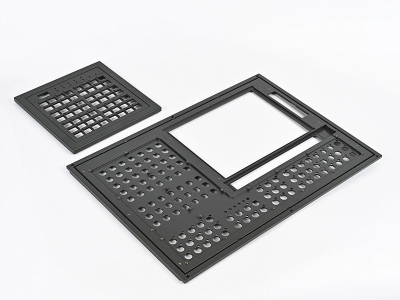
For OEM development teams, industrial designers, and product engineers, rapid prototyping is valuable only when the sample can answer real engineering questions. A prototype must do more than show shape. It often needs to validate assembly fit, thread engagement, sealing faces, mechanical load paths, thermal contact, surface finish feasibility, and dimensional compatibility with mating components. That is why many buyers turn to prototyping services based on CNC machining when they need parts made from real metals or engineering plastics instead of display-only concept models.
Compared with simplified mockups, rapid CNC prototyping is better suited to functional parts because it uses production-relevant materials, supports tighter tolerance control, and allows critical surfaces to be machined directly. This makes it highly effective for aluminum housings, stainless steel fixtures, titanium structural samples, copper electrical components, brass fittings, and engineering plastic parts for insulation, wear testing, or lightweight assembly validation. For buyers who already have CAD files, target materials, and testing goals, rapid CNC prototyping is often the most direct path from design to physically testable parts.
What Is Rapid CNC Prototyping?
Rapid CNC prototyping is the process of manufacturing prototype parts directly from digital design files using CNC-controlled cutting operations, usually without any dedicated mold or forming tool. The goal is to produce functional prototype components quickly while preserving realistic material behavior, dimensional accuracy, and surface quality. In practical product development, this means the prototype can be used not just for visual review, but also for assembly verification, structural evaluation, thread testing, sealing checks, limited thermal assessment, and pre-production engineering review.
This is why rapid CNC prototyping is especially valuable for applications where real material performance matters. If a part is intended to be made from aluminum, stainless steel, titanium, copper, brass, PEEK, POM, or another engineering material in later production, a CNC-machined prototype can reflect that material logic far better than a generic mockup. It can also reproduce critical planes, bores, slots, mating faces, and threaded features with much higher realism. For many buyers, this makes rapid prototyping through CNC machining one of the most reliable methods for reducing design risk before low-volume or full production decisions are made.
When Should You Choose CNC Prototyping Instead of 3D Printing?
CNC prototyping and 3D printing are both useful, but they solve different engineering problems. If the main requirement is fast appearance validation, early ergonomic review, or highly complex internal channels that do not yet need production-grade machining accuracy, 3D printing may be more economical. But when the prototype must represent actual material strength, true machined surfaces, realistic tolerances, threaded interfaces, or metal functional behavior, CNC prototyping is usually the stronger option.
For functional prototype programs, the most important question is not which process is newer or cheaper in general, but which process gives test results closest to the intended final product. If the part will later depend on tight flatness, accurate bores, machined sealing faces, bearing fits, threaded holes, or metallic mechanical performance, CNC machining usually provides more useful prototype data. This comparison is also closely related to 3D Printing.
Requirement | CNC Prototyping | 3D Printing |
|---|---|---|
Real material performance | More suitable | Limited by available print materials |
High-precision mating surfaces | More suitable | Usually requires post-machining |
Complex internal cavity structures | More limited | Often has an advantage |
Metal functional testing | More suitable | Depends heavily on print route and alloy availability |
Fast appearance verification | Usable | Often more economical |
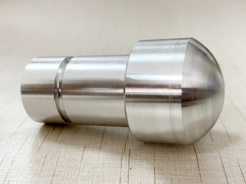
Materials Commonly Used for Rapid CNC Prototypes
Material selection in rapid CNC prototyping should follow the real purpose of the sample. The best prototype material is not always the cheapest or easiest to machine. It is the material that allows the engineering team to verify the most important product risks. In some cases, the prototype should use the exact intended production grade. In other cases, it may use a close substitute for early-stage design validation before the final material is locked.
Aluminum Prototypes
Aluminum prototypes are widely used for lightweight housings, brackets, covers, fixtures, robotic parts, heat-transfer structures, and consumer hardware. They are especially effective when buyers need fast machining, good dimensional stability, and practical cosmetic finishing options. Aluminum can support realistic functional testing for many structural and thermal applications while also keeping lead time relatively short.
For many rapid CNC prototype projects, aluminum is the preferred first-step metal because it balances machinability, strength-to-weight ratio, and surface treatment compatibility. Common routes often involve alloys under Aluminum.
Stainless Steel Prototypes
Stainless steel prototypes are used when corrosion resistance, higher structural rigidity, better wear resistance, or more realistic service-environment validation is needed. These prototypes are common for fluid-handling parts, medical-related hardware, industrial brackets, mechanical interfaces, and assembly components that must reflect the final product’s real corrosion or cleaning requirements.
Compared with aluminum, stainless steel prototypes generally require slower machining and stronger process control, but they provide more representative results when the production part will work in wet, chemical, or mechanically demanding environments. Buyers exploring this route often begin with Stainless Steel options matched to the target application.
Titanium Prototypes
Titanium prototypes are most suitable when the development program requires a high strength-to-weight ratio, corrosion resistance, or advanced material validation for aerospace, medical, or high-performance industrial components. These parts are typically not chosen for low cost, but for engineering realism. If the final part depends on titanium’s low density and high strength characteristics, using a different prototype metal can produce misleading test results.
Titanium prototype projects also demand more careful machining control, especially around heat concentration, thin-wall distortion, and finishing requirements. Projects in this category usually align with Titanium machining capability.
Superalloy Prototypes
Superalloy prototypes are used for the most demanding high-temperature, corrosion-resistant, and mechanically stressed applications. These are common in aerospace, power generation, oil and gas, and other sectors where material choice directly affects operational safety and lifecycle durability. Superalloy prototyping is typically requested only when performance realism matters enough to justify the higher machining difficulty and cost.
Because these materials are difficult to cut and expensive to waste, DFM review is especially important at the prototype stage. When the application requires this class of material, buyers often review Superalloy machining routes early in the RFQ process.
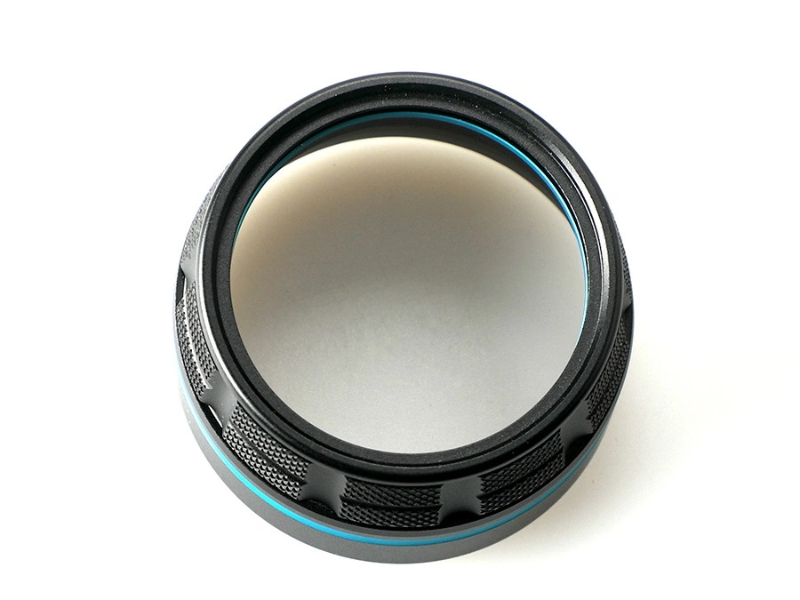
Plastic Prototypes
Plastic CNC prototypes are often selected for lightweight functional parts, insulating components, low-friction assemblies, medical or automation parts, and housing elements where engineering plastics offer the right balance of stiffness, wear behavior, and chemical resistance. They are highly valuable when the final product must be tested in real thermoplastic or high-performance polymer form rather than substituted with a metal display model.
Plastic prototypes are also useful when buyers need functional geometry quickly but still want machined surfaces, accurate bores, and more realistic fit than standard printed mockups can provide. Common selections are available within Plastic machining programs.
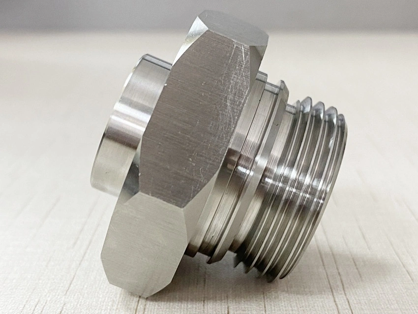
Copper and Brass Prototypes
Copper and brass prototypes are often used for electrical and mechanical test parts. Copper is typically selected when real conductivity or thermal performance must be validated, while brass is often preferred for machined fittings, connectors, precision threaded parts, and prototype components that need good machinability together with moderate conductive performance. These materials are especially useful in electrical, connector, heat-transfer, and fluid-system development.
For buyers comparing these options, Copper and Brass machining routes each support different prototype objectives.
What Information Is Needed to Quote CNC Prototype Parts?
A good prototype quote depends on more than just a 3D model. If buyers want accurate lead time, correct process selection, and realistic technical feedback, the RFQ package should clearly describe the part’s functional intent, not only its geometry. The supplier needs enough information to understand which dimensions matter, which surfaces must be machined precisely, whether the part is for appearance review or real testing, and whether future low-volume production is likely.
Required RFQ Information | Why It Matters | Typical Impact on Quote |
|---|---|---|
3D CAD file | Defines geometry, machining access, and process scope | Primary basis for manufacturability review |
2D drawing with tolerances | Identifies critical dimensions, datums, and inspection needs | Strong impact on cost and process route |
Material grade | Determines machining difficulty and functional realism | Affects tool selection, cycle time, and price |
Quantity | Changes setup logic and per-part pricing | Determines prototype vs small-batch approach |
Surface finish | Clarifies whether the part is for function, appearance, or both | May add secondary processing cost |
Inspection requirements | Defines how quality must be verified | Affects reporting, lead time, and QA effort |
Delivery expectation | Helps prioritize route planning and scheduling | Impacts capacity and urgency assessment |
How Neway Supports Prototype-to-Production Development
At Neway, rapid CNC prototype projects are not treated as isolated samples. They are evaluated as part of a broader product development path. That means the engineering review considers not only how to machine the first part quickly, but also how the part may evolve into repeatable manufacturing later. This is especially useful for buyers who are moving from functional validation toward pilot supply or early market release.
Support across that path can include CNC machining prototyping for fast-turn functional samples, precision machining for tolerance-sensitive interfaces, multi-axis machining for complex geometry and reduced setup transfer, and low-volume manufacturing for bridge production after the design is validated. Combined with surface finishing and inspection planning, this prototype-to-production route helps reduce the gap between early engineering parts and later stable supply.
Request a Quote for Rapid CNC Prototype Parts
If your project requires functional metal or plastic prototype parts with real material performance, accurate assembly features, and fast engineering turnaround, rapid CNC prototyping is often the most effective route. It is especially suitable for buyers who already have CAD files, target materials, and clear test objectives, and who need parts that can move beyond concept review into real functional validation.
To speed up evaluation and quoting, provide your 3D file, 2D tolerances if available, material grade, quantity, finish requirement, and delivery target. If the project may continue into pilot batches or repeat supply, mentioning that early also helps define a more scalable process route. For projects focused on functional development and future manufacturability, Neway’s prototyping services can support a more efficient path from sample validation to production planning.
FAQ
What is the best process for custom prototype parts: CNC machining, 3D printing, or rapid molding?
What files are needed to get a quote for rapid CNC prototyping?
Can prototype parts be made with the same material and tolerances as production parts?
How do I reduce the cost of rapid prototyping without affecting functional testing?