Prototype Manufacturing Services: Choosing CNC Machining, 3D Printing, or Rapid Molding Service
Prototype Manufacturing Services: Choosing CNC Machining, 3D Printing, or Rapid Molding for Your Project
Choose CNC machining when a prototype must reproduce a specified material condition, machined datum relationship, thread, fit, or sealing surface. Choose 3D printing when geometry learning, internal access, or iteration speed matters more than production-equivalent material behavior. Choose rapid molding when the test depends on molded resin, gate location, shrinkage, knit lines, ejection, or repeated plastic parts. None of these routes is universally best. The correct choice is the process that can reproduce the condition being tested, expose the relevant failure, and deliver evidence against a written acceptance rule. Process names are only a starting point. CNC evidence depends on stock form, cutting sequence, workholding, deburring, finish, and inspection state. Additive evidence depends on process, feedstock, orientation, supports, thermal history, and post-processing. Molding evidence depends on resin state, cavity, gate, packing, cooling, and ejection. Buyers need those conditions before a process comparison becomes technically meaningful.
Before comparing price or turnaround, define the decision that the sample must support: packaging approval, assembly fit, functional load, fluid sealing, thermal behavior, appearance, or a bridge-production release. Record the production material and route, quantity, critical features, final finish, inspection state, and differences that would invalidate the result. This test-first brief lets suppliers review prototype manufacturing services against the same scope instead of quoting three processes that answer different questions. It also prevents an early geometry pass from being treated as proof of material performance or future production capability. Define who owns each decision, what evidence that person must receive, and whether a failure causes redesign, another specimen, or a process change. If several questions remain open, divide them among controlled specimens rather than forcing one part to serve incompatible purposes. The useful outcome is not merely a finished prototype; it is a traceable answer that allows the program to release, hold, or revise the next stage.
Why Process Selection Must Follow the Validation Question
A prototype is useful only within the boundary of the conditions it represents. A printed housing can confirm envelope clearance while giving weak evidence about a machined alloy thread. A CNC-machined plastic sample can prove a datum and assembly stack while omitting molded shrinkage, fiber orientation, gate vestige, or ejection marks. A rapid-molded part can reveal resin and cavity behavior while leaving future production-tool cooling or multi-cavity variation unresolved. Buyers should therefore separate fit, function, material response, appearance, and process readiness into distinct acceptance decisions rather than allowing one successful sample to release every question. The boundary should be written before testing. State the represented material and manufacturing state, known deviations, sample quantity, measurement method, and conclusions that remain excluded. This prevents a visually impressive specimen from gaining authority that its route cannot support. It also makes disagreement actionable: engineering can request a production-representative condition, quality can define acceptance evidence, and sourcing can compare the cost of resolving the actual uncertainty.
The comparison should use equal test conditions. Each quote needs the same controlled revision, material requirement, quantity, finish, critical-characteristic list, test environment, inspection evidence, and delivery event. Where routes cannot match, the supplier should state the difference and the revalidation it creates. Lead time begins at a defined release event, not at an informal file upload. Cost includes the evidence required for acceptance, not just fabrication. A process that starts quickly but cannot produce valid test evidence is slower and more expensive than a route that resolves the engineering decision in one controlled cycle. Quantity changes the comparison as well. One appearance model, several destructive-test specimens, and a repeated molded pilot create different setup, tooling, inspection, and variation needs. Buyers should specify first-part approval, balance release, destructive units, spares, lot splits, and delivery events. A low unit price based on a different quantity or inspection scope is not an equal comparison.
Buyer decision | Condition the prototype must reproduce | Failure if the condition is omitted |
|---|---|---|
Release an assembly interface | Datums, mating parts, fit, threads, finish allowance, and final inspection state | A false clash or false clearance passes into the next revision |
Approve a functional load test | Grade, condition, product form, load direction, geometry, and test fixture | The result describes a surrogate material or setup rather than the intended part |
Validate a sealing feature | Datum relationship, roundness, texture, coating, compression, and fluid conditions | Leakage risk remains hidden behind nominal dimensions |
Review complex packaging geometry | Envelope, internal access, support-removal limits, and representative mating components | A visually complete shape cannot be assembled or cleaned as intended |
Assess a molded plastic design | Resin, gate, draft, wall transitions, shrinkage, cooling, texture, and ejection route | Warpage, sink, knit-line, or cosmetic behavior appears only after tooling commitment |
Authorize the next supply stage | Accepted evidence, open deviations, change authority, repeat quantity, and transfer plan | An unresolved prototype assumption becomes an uncontrolled production requirement |
Use CNC Machining for Material, Datum, and Interface Evidence
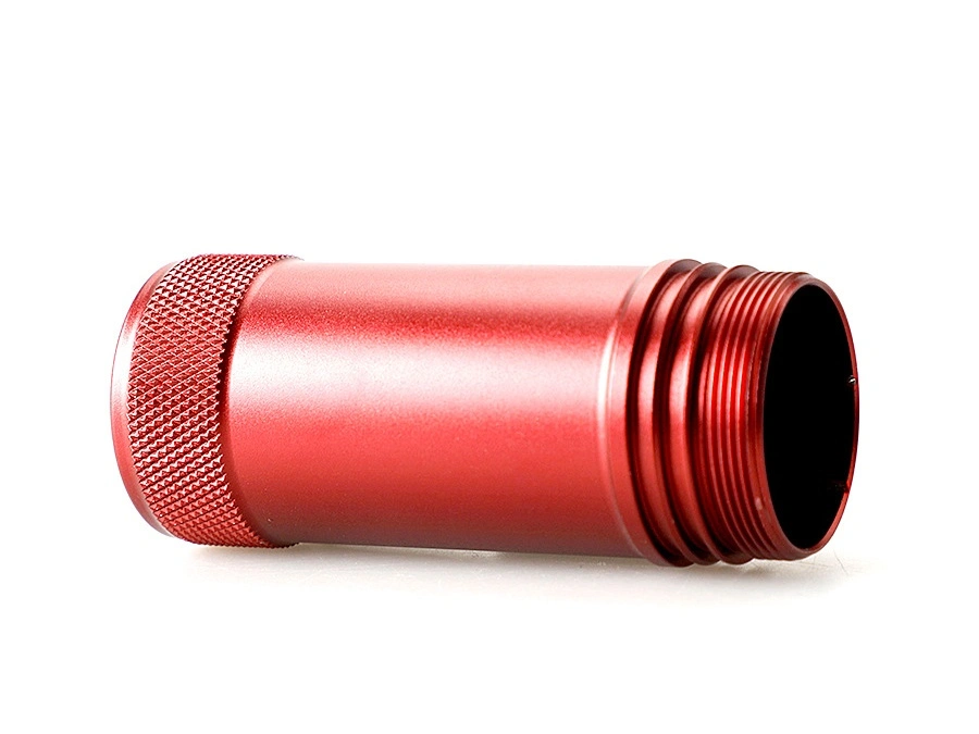
CNC machining is the stronger route when the decision depends on a wrought, cast, or engineering-plastic stock condition and on features created by cutting. Bores, sealing faces, bearing seats, threaded interfaces, precision datums, and post-machining finishes can be evaluated in a production-relevant material when the specified grade, temper or heat treatment, product form, and final surface state are available. Cutting also exposes workholding load, tool access, burr formation, heat, tool wear, and residual-stress release. Those effects matter because a thin wall can move after unclamping, a bore can drift as a tool wears, and coating can alter a fit that passed before finishing. Setup planning is therefore part of the evidence. The drawing should establish functional datums rather than rely on convenient stock faces, and the inspection plan should measure the part in the state used for acceptance. Deep pockets, long tools, interrupted cuts, slender features, and multi-axis access can change deflection, heat, and measurement strategy. If these mechanisms control the test result, machining sequence and final-state verification belong in the quoted scope.
The limits must be explicit. A part machined from plate does not automatically represent a future casting, forging, molded blank, or differently heat-treated stock. A machine setting, controller resolution, or measuring-device resolution does not establish finished-part conformance. For CNC machining prototyping, the RFQ should identify material grade and condition, stock form, datum scheme, critical features, edge requirements, finish, inspection after unclamping and post-processing, mating parts, and acceptance method. Ask the supplier to identify setup changes, inaccessible features, measurement limits, and any condition that must be revalidated when the prototype transfers to another material form, fixture, supplier, or production route. Also distinguish a functional prototype from a capability study. One accepted part can show that the tested specimen meets the defined requirement; it cannot establish a stable distribution across future lots. Repeated production needs change control, sampling, measurement-system suitability, material traceability, and time-ordered evidence. Keep these later decisions open unless the prototype program explicitly includes them.
Use 3D Printing for Geometry Learning and Controlled Iteration
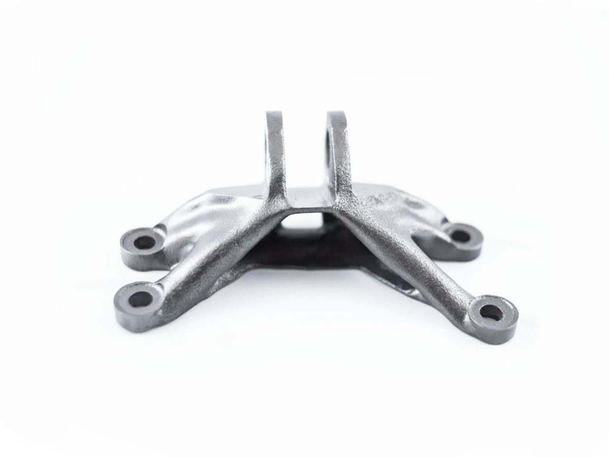
3D printing is effective when the open question is geometric: overall form, packaging space, internal passages, lightweight structures, user interaction, or rapid comparison of CAD revisions. The relevant route is not simply "3D printing." The additive process, feedstock, build orientation, layer strategy, supports, thermal history, post-processing, cleanup, and inspection access determine what the part can prove. ISO/ASTM 52900 terminology can identify additive-process categories, but a category name alone does not establish dimensional, mechanical, surface, or environmental equivalence for a specific prototype. The test plan should identify which orientation and post-processing state are accepted. A channel may exist in CAD yet retain powder or resin after manufacture. A thin wall may print but distort during support removal or thermal treatment. A mating bore may need machining after printing, which creates a hybrid datum and inspection route. These details belong in the process review because they change both evidence and delivery.
Printed parts can show direction-dependent response, support scars, porosity, trapped material, distortion, stair-stepped surfaces, or feature closure. These conditions may be acceptable for an envelope study and unacceptable for pressure, fatigue, sealing, wear, or a controlled fit. When using 3D printing services, define whether the result is visual, dimensional, assembly, flow, thermal, or mechanical. State build orientation, required post-processing, critical-feature method, inspection access, and invalidating differences from the intended product. A hybrid printed-and-machined specimen can be appropriate when additive geometry is needed but a datum or interface requires a controlled machined condition. Buyers should not transfer a pass from one additive process, machine, feedstock lot, orientation, or post-processing route without reviewing the changed condition. When speed is the reason for selection, define the earliest acceptable evidence event. A fast build followed by uncertain cleanup, outsourced heat treatment, or inaccessible inspection may not provide the earliest defensible result.
Use Rapid Molding for Resin, Cavity, and Repetition Evidence
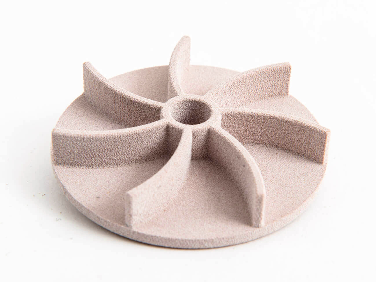
Rapid molding is appropriate when the test depends on behavior created by molding rather than on plastic chemistry alone. Filling, packing, cooling, shrinkage, knit lines, sink, warpage, gate vestige, draft, texture, and ejection can influence assembly, sealing, appearance, and dimensional stability. The intended resin grade, moisture or conditioning state, colorant, regrind rule, gate position, cavity design, process window, and final test state should match the decision. A molded sample can therefore answer questions that a machined or printed plastic surrogate cannot, especially when repeated parts are needed to observe cavity or lot behavior. Wall transitions, bosses, ribs, inserts, and flow length should be reviewed as a system. Changing a gate can relocate a knit line; changing packing can affect sink and dimensions; changing conditioning can alter a hygroscopic resin after molding. Inspection timing and environment must therefore be part of the acceptance plan rather than an informal afterthought.
Rapid tooling remains a controlled approximation, not automatic proof of the production process. Tool material, cavity count, cooling, venting, surface treatment, cycle, automation, and measurement plan may change during transfer. Buyers using rapid molding services should define whether the pilot releases assembly, appearance, sealing, aging, or use testing; record every difference from the planned production mold; and identify tests that repeat after a tool, cavity, resin, or process change. Tooling should be approved only after the frozen design, quantity, gate and cosmetic rules, dimensional acceptance, and nonconformance authority are clear. Sample quantity should reflect the intended evidence. A few parts can support an assembly check, while destructive testing or a review of cavity-to-cavity behavior requires a planned set. Buyers should identify hold points for tool adjustment, first-off review, process changes, and balance release so that speed does not override controlled learning.
Choose the Route by the Earliest Defensible Test Result
Compare processes by the first accepted result they can produce, not by headline fabrication speed. Start with the failure that would block the next decision, then identify the material, geometry, manufacturing state, quantity, and measurement needed to reveal it. If one specimen cannot represent every condition, divide the program into controlled samples. A form model, a functional CNC specimen, and a molded pilot can each answer a different question without pretending that one convenient route proves all three. Cost should be normalized to the same evidence package: setup or tooling, material, fabrication, post-processing, inspection, documentation, destructive units, rework response, and revalidation. The cheapest fabrication line can become the most expensive program when it omits the test condition that later forces another round. Record the selected route, rejected alternatives, key assumptions, and the event that closes each remaining risk.
Required evidence | Process route and release condition |
|---|---|
Machined alloy fit, thread, datum, or sealing surface | CNC machining, after material state, setup, final finish, and inspection method are approved |
Fast envelope, ergonomic, or internal-passage learning | 3D printing, after process, orientation, supports, cleanup, and geometric acceptance are defined |
Molded resin, gate, shrinkage, or ejection behavior | Rapid molding, after resin, cavity, gate, conditioning, and test state are released |
Different geometry and interface questions in one program | A controlled hybrid sequence with separate acceptance decisions for each specimen |
Repeated functional parts before full production | CNC machining or rapid molding, selected from the intended route and variation risk |
Prototype followed by a repeatable supply stage | Prototyping plus low-volume manufacturing, with transfer differences and revalidation triggers documented |
Move From Prototype Evidence to a Controlled Low-Volume Release
A prototype pass releases only the conclusions covered by its recorded conditions. Before low-volume manufacture, freeze the CAD and drawing revision, material grade and condition, intended stock or molding route, critical characteristics, datums, finish, inspection method, test environment, accepted deviations, and authority for change. Separate design validation from process validation. One conforming part can demonstrate a specified function, but it does not prove stable capability across setups, cavities, operators, material lots, outside processes, or time. The transfer plan should identify first-part evidence, balance-release approval, sampling, traceability, nonconformance disposition, packaging, and every test that repeats after a process change. Review the prototype bill of process beside the proposed low-volume route. A new fixture, larger stock allowance, alternate cutter access, different print orientation, production resin, another finish supplier, or revised cavity can affect validated features. Mark each difference as accepted, requiring evidence, or prohibited until engineering approval.
Consider a hypothetical pump-cover program, not a Neway customer case. A printed cover may confirm envelope and hose routing; a CNC-machined cover in the specified alloy can test the datum-controlled sealing face and threaded ports; a later molded or cast route may introduce different shrinkage, porosity, residual stress, or surface conditions. The buyer should release each specimen only for its stated question and repeat affected tests after the route changes. A later move toward mass production requires production tooling, workholding, measurement-system review, control planning, and time-ordered evidence rather than reliance on the prototype result alone. The scenario also shows why a hybrid program is not wasteful duplication. Each specimen removes a different uncertainty. Waste occurs when an expensive specimen is asked to prove a condition it does not reproduce, or when a route change silently invalidates evidence already used for release.
Prepare a Process-Neutral RFQ and Evidence Plan
A useful RFQ allows each route to be assessed against the same decision. Provide controlled 3D CAD and a 2D drawing where requirements need definition. State the revision, material grade and condition, expected production route, quantity, delivery split, critical features, datums, threads, surface texture, finish, and cosmetic zones. Include mating information, use environment, test input and output, acceptance limits, inspection records, and destructive-test quantities. State which document governs a conflict, who may approve substitutions, and which changes trigger a new quote or revalidation. Ask suppliers to return assumptions, exclusions, proposed deviations, inspection scope, start and finish events, and unresolved holds. For each critical characteristic, connect the drawing requirement to the test or measurement, the state in which it is checked, and the authority that can accept a deviation. Without that connection, competing quotes can appear equivalent while pricing different levels of engineering risk.
Use a technical review through prototype manufacturing services to compare whether CNC machining, 3D printing, rapid molding, or a staged combination can produce the required evidence. The final selection should identify what the sample will prove, what it will not prove, how acceptance will be measured, and what must happen before the next supply stage. If two quotations rely on different materials, finishes, inspection deliverables, or test boundaries, normalize those differences before comparing price or lead time. Release manufacture only when the quoted process and the test plan answer the same engineering question. Preserve the selected assumptions with the purchase release and prototype report. When design, material, route, supplier, finish, quantity, or inspection changes, review the affected evidence before carrying the old result forward. This discipline turns process selection into a controlled engineering decision instead of a one-time preference.
FAQ
What is the best process for custom prototype parts: CNC machining, 3D printing, or rapid molding?
What files are needed to get a quote for rapid CNC prototyping?
Can prototype parts be made with the same material and tolerances as production parts?
How do I reduce the cost of rapid prototyping without affecting functional testing?