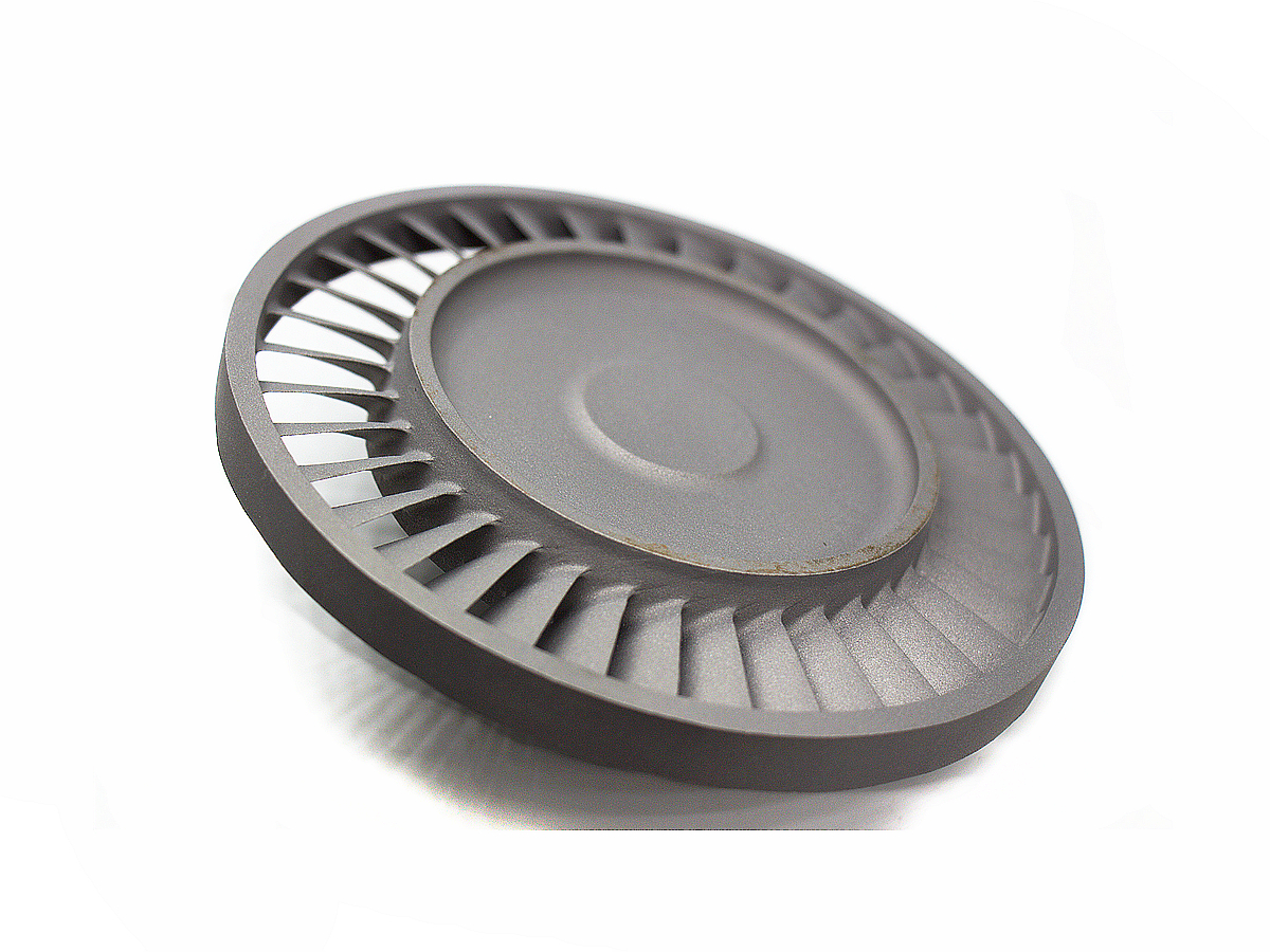
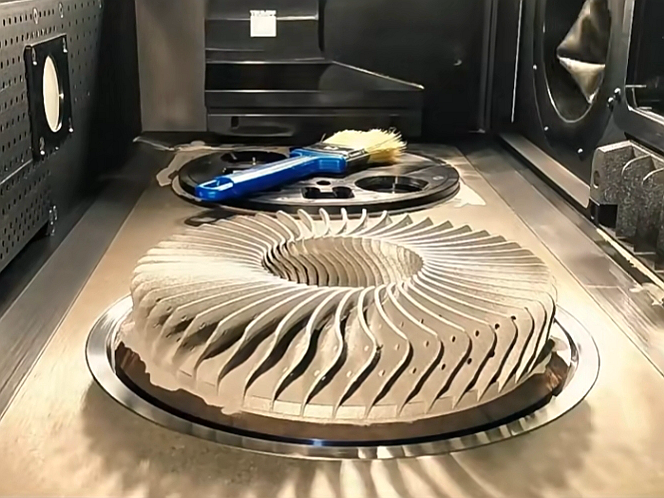
Inconel 3D Printing Service: Direct Metal Laser Sintering (DMLS)
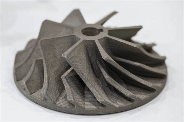
Introduction: When Superalloys Meet Additive Manufacturing
Inconel DMLS is suited to complex nickel-alloy parts when internal channels, part consolidation, low-volume demand, or high billet waste justify additive building and post-processing. It is not the default for every Inconel component: accessible prismatic geometry, high annual volume, or tight finished interfaces may favor forging, casting, or CNC machining. The buyer must compare the complete route rather than print price alone. DMLS earns its place when it creates a geometry or production path that conventional processes cannot deliver economically, while leaving machinable stock and verifiable access for critical features. A useful RFQ should identify the CAD and drawing revision, exact Inconel grade and condition, quantity, datums, surface finish, post-processing sequence, inspection method, and certification package. Those inputs show whether DMLS reduces total manufacturing risk or merely transfers cost to heat treatment, machining, cleaning, and inspection.
What Is Inconel and Why Is It Difficult to Machine?
Inconel is a family of nickel-chromium-based superalloys selected for oxidation resistance, corrosion resistance, creep strength, and strength retention at elevated temperature. In additive and CNC manufacturing discussions, Inconel 718 and Inconel 625 are common reference grades, but they are not interchangeable. Inconel 718 is precipitation-hardenable and needs the specified thermal route when age-hardened strength is required. Inconel 625 is solid-solution-strengthened and is often selected for corrosion resistance and weldability. ASTM F3055-14a (2021) covers full-melt powder bed fusion components in UNS N07718, while ASTM F3056-14 (2021) covers UNS N06625. These product specifications define requirements for their stated alloys and processes; they do not approve a supplier or guarantee an arbitrary geometry. Powder condition, oxygen exposure, heat treatment, build orientation, and final inspection still determine whether a printed part meets its drawing. The RFQ must therefore identify the exact alloy designation, required material condition, applicable specification revision, coupon orientation, and acceptance tests rather than relying on the trade name alone.
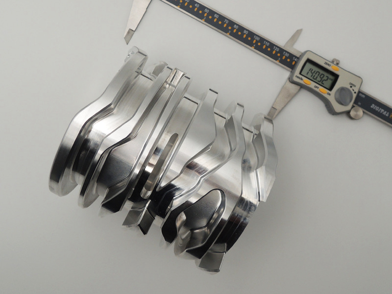
The same properties that make Inconel useful in hot and corrosive environments also make it difficult for conventional Superalloy CNC Machining Service. Nickel alloys work harden quickly, conduct heat poorly, and place high load on cutting edges. Tool notching, built-up heat, burr formation, and residual-stress movement can appear when the tool path, coolant, fixture, or roughing sequence is not controlled. Deep pockets, thin walls, interrupted cuts, and small internal passages increase the difficulty because the tool must remove heat and chips from a restricted zone. CNC machining is still essential for many Inconel parts, especially for datums, threads, sealing faces, and close-tolerance interfaces. DMLS changes the blank-making route; it does not remove the need for engineering review, heat treatment, machining allowance, deburring, and final measurement. A common hybrid decision is to print the difficult internal geometry and machine the features that control assembly, sealing, or bearing fit.
Direct Metal Laser Sintering (DMLS) Technology Explained
DMLS is a metal laser powder bed fusion process that builds a near-net-shape part from 3D CAD data. A laser selectively melts thin layers of Inconel powder in an inert chamber, and the build platform lowers after each layer. The method is valuable when the design needs internal flow paths, lightweight lattice regions, integrated brackets, curved manifolds, or geometry that would require several assemblies if made by machining. The process should be judged as a controlled manufacturing route, not as a shortcut that automatically produces finished parts directly from powder. The output condition depends on the build file, powder lot, machine state, thermal history, and downstream processing.
A practical DMLS workflow starts with DfAM review, build orientation, support design, powder and parameter selection, and build-plate layout. During printing, layer thickness, laser energy, scan strategy, recoating stability, oxygen level, and thermal history influence density, residual stress, roughness, and distortion risk. Build orientation affects support scars, surface roughness, mechanical test direction, powder evacuation, and later tool access. A tall dense build may create more residual stress than a short open geometry, while an enclosed channel may print well but fail inspection if powder cannot be removed. After printing, the part usually remains attached to the plate and needs controlled cooling, depowdering, wire EDM separation, support removal, dimensional review, and heat treatment. The buyer should treat the printed shape as an intermediate condition unless the drawing specifically accepts an as-built surface, as-built dimensions, and as-built material condition. Useful review questions include where the datum structure begins, which faces need machining stock, whether internal powder can escape, and whether the selected inspection method can actually reach the critical feature.
Five Key Advantages of Choosing Inconel DMLS
Design Freedom for Internal Features: DMLS can produce conformal cooling channels, enclosed passages, lattice structures, thin ribs, and organic transitions that are difficult or impossible to cut from solid stock. The advantage is strongest when those features improve heat transfer, reduce pressure loss, reduce weight, or eliminate brazed and welded joints. The design still needs powder escape paths, support access, minimum wall review, and inspection planning. A good DfAM review will also decide which surfaces remain printed and which surfaces need machining stock for tolerance, sealing, or assembly. If a channel is straight, accessible, and easy to drill, DMLS may not be justified; if the channel curves around a thermal load or merges several passages, additive manufacturing becomes more valuable.
Functional Integration and Lightweighting: Multiple machined, welded, or bolted components can sometimes be redesigned as one printed part. This can remove fasteners, reduce leak paths, reduce assembly labor, and improve stiffness-to-weight ratio. The benefit depends on whether integrated features can be printed, cleaned, heat treated, machined, and inspected. A consolidated design that cannot be depowdered or verified is not a production-ready DMLS design. Buyers should ask how consolidation changes inspection access, repair options, and replacement cost before treating part reduction as an automatic benefit. One-piece construction can reduce assembly risk, but it can also make a damaged feature harder to replace.
Qualified Material Performance: Inconel DMLS parts can reach demanding mechanical targets when the powder, machine, process window, build orientation, heat treatment, and inspection route are qualified together. The correct comparison is not “printed versus forged” in general. The correct comparison is the specified grade, material condition, test direction, coupon plan, acceptance standard, and service load. Fatigue-sensitive parts need particular attention to surface roughness, internal porosity, HIP requirements, and machined notches. Buyers should define whether properties are needed on witness coupons, actual part coupons, or final machined features, because each method answers a different engineering question. Test orientation matters because build direction, support strategy, and heat treatment can change the measured result.
Significant Reduction in Material Waste and Higher Utilization: DMLS is a near-net-shape process, so it can reduce chip waste compared with subtractive routes such as CNC Milling Service from expensive billet. The saving is most relevant when the buy-to-fly ratio is high or the geometry removes large amounts of stock. Powder reuse must still be controlled by sieving, contamination limits, and powder-life rules, and finishing stock should be included for critical machined features. The most accurate cost comparison includes powder, build time, support removal, heat treatment, machining, scrap risk, inspection, and certification, not raw material utilization alone. DMLS may save material but still lose the total-cost comparison if every surface needs heavy machining.
Faster Prototyping and Time-to-Market: DMLS can shorten early design loops because tooling is not required and complex metal prototypes can be built directly from CAD. It is especially useful when a functional prototype needs internal channels, thin walls, or geometry that is costly for CNC Machining Prototyping. The schedule advantage can disappear if the prototype needs HIP, full heat treatment, precision machining, NDT, or a complete certification package, so those requirements should be stated before quoting. The best early prototype plan separates geometry validation, thermal-performance testing, mechanical testing, and production qualification instead of forcing every prototype to carry full production documentation. That separation helps buyers learn quickly without overbuying documentation for a design that may still change.
Key Post-Processing Steps for Inconel DMLS Parts
Inconel DMLS quality is decided after printing as much as during printing. Post-processing should be planned before the build, because support strategy, machining allowance, heat-treatment sequence, and inspection points affect one another. A drawing that only says “3D printed Inconel” leaves too many acceptance questions open. The process plan should state whether the part is accepted as-built, stress relieved, HIP processed, solution aged, machined after heat treatment, finished after machining, or inspected at several stages.
Support Removal and Surface Cleaning: Parts are commonly separated from the build plate by wire EDM, then supports are cut, ground, or finished away. Processes such as CNC Part Tumbling and Deburring may help remove light burrs and loose powder from accessible surfaces. Thin walls, sealing lands, and datum pads need protection because aggressive finishing can round edges, damage reference surfaces, or trap media inside channels. If internal passages are part of the function, the RFQ should define cleaning method, powder-removal evidence, and inspection access. Possible validation methods include borescope review, flow testing, weight comparison after depowdering, or sectioning on development samples when the feature is critical.
Critical Heat Treatment: For precipitation-hardened alloys such as Inconel 718, solution treatment and aging through a specified route such as Heat Treatment for CNC Machining can control strength, hardness, and residual stress. The thermal route should match the material specification, the build process, and the final drawing. Stress relief may be needed before support removal or finish machining so the part does not move after unclamping. HIP may be required for fatigue, pressure, or critical service parts, but it should be specified by acceptance need rather than added as a vague quality label. Records such as furnace charts, hardness checks, coupon results, or HIP cycle documents should be requested only when they are needed for acceptance.
Surface Finishing to Enhance Performance: Finishing should be selected by surface function, not appearance alone. Electropolishing for Precision Parts can reduce micro-burrs and smooth accessible flow surfaces, but it removes material and can change small edges or holes. For visible or manually handled surfaces, CNC Part Polishing Service may be useful, but functional surfaces still need roughness targets, masking instructions, and final dimensional checks. Finishing after machining should also be reviewed for burr direction, oxide condition, and whether the finish changes a critical fit. No-touch surfaces, sealing lands, internal passages, and marked datums should be called out clearly on the drawing.
Inconel DMLS vs. Traditional CNC Machining: How to Choose?
Choose DMLS when the part value comes from geometry that cannot be made efficiently by cutting, such as internal cooling, curved channels, topology-optimized ribs, integrated manifolds, or consolidated assemblies. Choose conventional machining when the geometry is accessible, the blank is available, the quantity is high, and the main requirement is tight tolerance, known surface finish, or low unit cost. Precision Machining Service also remains necessary after DMLS when bores, threads, datum faces, seal grooves, and bearing surfaces must meet final drawing requirements. A common failure mode is to print a complex near-net blank without leaving enough stock or access for the final datum strategy. Another is to accept an as-built surface in a fatigue-sensitive zone that should have been machined, polished, or shot-peened under a controlled specification.
A practical selection rule is to compare the complete route, not only the print or cut step. When the part has complex internal channels, integrated structures, or low-volume/prototype demand, DMLS may be the better starting blank. When the part is simple and the annual volume is high, traditional multi-axis machining services may be more economical and easier to qualify. A hybrid route through One Stop Service Service can combine DMLS near-net-shape building with 5-axis machining, EDM, heat treatment, and final inspection when the drawing needs both additive geometry and precision interfaces. Buyers should ask which features are printed, which are machined, which are inspected after heat treatment, and which surfaces control assembly. A clean decision package usually includes three options: fully machined, DMLS plus finish machining, and conventional blank plus secondary operations.
Industry Application Cases of Inconel DMLS Technology
Aerospace and Aviation: Consider a hypothetical Inconel 718 combustor manifold with curved cooling passages and two machined sealing faces. This planning example is not a Neway customer project. Additive value comes from integrating the passages; principal risks are trapped powder, build distortion, rough internal flow surfaces, and datum shift after stress relief. The process plan would provide powder-escape access, orient the part to protect the passages, add finish stock on sealing faces, stress relieve before plate separation, apply the specified thermal route, and machine final datums after thermal processing. Validation would combine documented depowdering, borescope or CT review with a stated detection limit, flow testing, dimensional inspection of the sealing interfaces, and coupon tests tied to build orientation and material condition. Production release should follow only after the development route demonstrates both passage function and final datum recovery. If either result fails, the buyer should revise channel access or compare the printed route with a machined and joined assembly.
Power Generation: Turbine, valve, burner, and heat-resistant hardware may benefit from DMLS when channels, transitions, or repair-related geometries are difficult to machine. Material choice must be separated from process choice. A drawing that calls for Hastelloy C-276 or another nickel alloy should be reviewed for corrosion environment, temperature, powder availability, post-processing route, and final inspection needs. In these parts, pressure boundary, oxidation exposure, and thermal cycling often matter more than visual surface appearance. Qualification may require dimensional inspection after thermal processing because roughing, heat treatment, and finishing can each shift the final datum relationship.
Medical Device: DMLS can support customized surgical guides, fixtures, porous structures, and orthopedic-related components when the material, cleaning route, surface condition, and regulatory requirements are defined. Patient-specific geometry is a strong additive use case, but medical applications require controlled documentation, biocompatibility review where applicable, cleaning validation, traceability, and inspection rather than a simple print-and-ship approach. Surface roughness, trapped powder, and finishing media should be reviewed early because they affect cleaning and acceptance. The buyer should separate prototype-fit evaluation from production release, since the documentation burden is different.
Neway’s Inconel DMLS Service Capabilities
For buyers evaluating Neway’s Inconel DMLS route, the useful question is how alloy selection, DfAM review, build planning, post-processing, precision interfaces, and inspection connect in one manufacturing plan. Material selection may involve high-temperature grades such as Inconel 738 or broader Inconel Alloy requirements. The process plan may also include support removal, slotting, hole finishing, or contour features through Electrical Discharge Machining (EDM) Service. Early Prototyping Service should validate geometry and material condition before scaling into Low Volume Manufacturing Service. The RFQ should identify which features are printed, which are machined, which surfaces are finished, and which reports are needed for acceptance. Useful attachments include STEP or native CAD, 2D drawings, critical-to-quality notes, expected operating temperature, pressure or fatigue conditions, and any required material or inspection standards. The supplier workflow should connect DfAM feedback, build release, thermal processing, secondary machining, surface finishing, and inspection into one revision-controlled route.
Conclusion: Embracing the Future of Manufacturing
Inconel DMLS is most valuable when a demanding nickel-alloy part needs complex geometry, thermal performance, part consolidation, or low-volume flexibility that conventional manufacturing cannot provide efficiently. It should be selected with its full process chain in mind: DfAM review, printing, heat treatment, support removal, CNC machining, finishing, inspection, and certification. A clear RFQ should define the grade, drawing condition, critical dimensions, finish, post-processing route, quality evidence, and production volume before the manufacturing route is chosen. If those details are missing, the first step is not printing; it is engineering clarification. That clarification protects cost, lead time, and acceptance before powder, machine time, and post-processing capacity are committed.
FAQs