CNC Prototyping Service: How to Validate Design Before Production
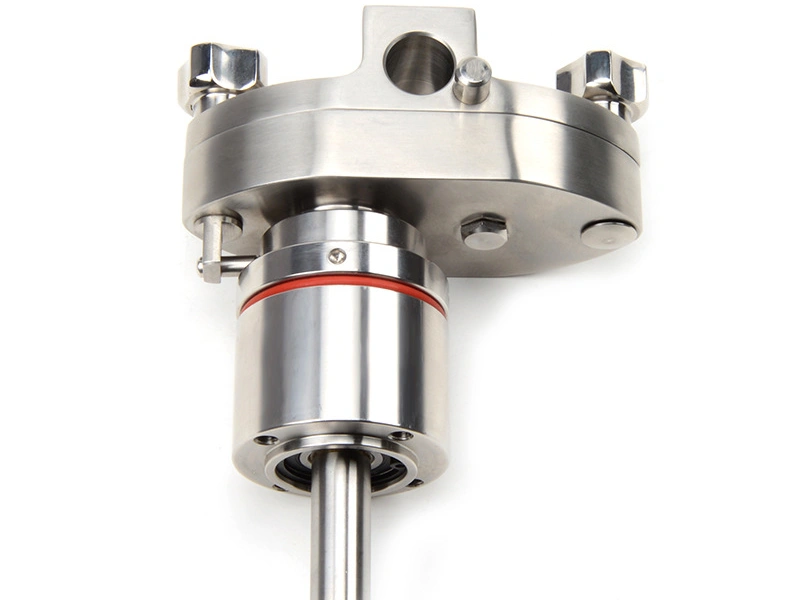
A CNC prototyping service validates a design before production by turning specific design assumptions into measurable evidence from a machined part. The prototype must represent the material condition, geometry, datums, surface state, and functional interfaces that matter to the decision. It cannot prove variables that its stock form, setup, finish, or test method does not represent. A useful program therefore starts with the question to be answered, identifies the critical characteristics and failure modes, and defines what result will approve a revision, trigger a design change, or require another representative build.
For a buyer, the central question is not whether a prototype looks finished. It is whether the proposed part and test plan can support the next engineering decision without creating false confidence. The RFQ should state the controlled drawing revision, exact material and condition, required finish state, mating parts, datum scheme, critical dimensions, functional tests, acceptance rules, and intended production route. A broader prototyping service can then be compared by the evidence it will deliver, not simply by unit price or machining speed. Results should be recorded against the defined question before the design is released or revised.
What Is a CNC Prototyping Service?
A CNC prototyping service produces existing development parts from controlled CAD data and drawings so a team can evaluate selected geometry, interfaces, material behavior, and manufacturing risks before production release. CNC milling, turning, drilling, and related subtractive operations can create measurable datums, bores, sealing features, threads, and mating surfaces in specified engineering stock. The service is most useful after the design authority can define a testable question but while the revision can still change. The output is not merely a part; it is a part, an inspection scope, a test boundary, and a disposition that connects observed evidence to a design decision.
CNC machining is appropriate when the question depends on features that a visual model cannot represent reliably. Examples include pin-to-hole location from a defined datum, thread engagement with production hardware, seal-groove geometry, bearing-seat alignment, or thin-wall movement after unclamping. Evidence remains limited by the prototype route. A part machined from plate may validate accessible geometry and assembly fit, yet it may not reproduce the grain flow, porosity, residual stress, draft, or wall distribution of a future casting or molding. The buyer should name both the question the prototype must answer and the production variables that remain outside the test.
Why CNC Prototyping Matters in Product Development
CNC prototyping matters because it allows a design team to replace an untested assumption with physical evidence while changes are still manageable. A machined part can reveal datum-transfer errors, inaccessible tool paths, weak edge conditions, interference at assembly, or distortion that was not evident in CAD. These findings are useful only when the team knows which revision was built, how the part was restrained and measured, and whether the tested material and finish represent the intended use. Without those controls, a dimensionally acceptable sample can still answer the wrong engineering question.
The prototype gate should match the development stage. Early work may only need envelope and assembly access. Engineering validation may require final material condition, defined critical-to-quality characteristics, mating hardware, and a controlled functional test. A pre-production decision may also require a representative fixture, finishing route, inspection method, and repeatable result across more than one part. Approval for one gate does not automatically approve the next. Before moving toward low-volume manufacturing, record which variables were demonstrated, which were screened only, and which still require a pilot build or production-route validation.
Development Goal | How CNC Prototyping Helps | Main Validation Benefit | Risk Reduced |
|---|---|---|---|
Confirm an assembly interface | Machine the locating holes, mating faces, and hardware features from the controlled revision | Inspect from the assembly datums, then build with the specified mating parts | Reject or revise the interface if alignment, clearance, or stack-up fails |
Evaluate functional behavior | Use a material and condition that represent the property being tested | Run a defined load, motion, sealing, or thermal test within the stated boundary | Avoid approving performance from a cosmetic or nonrepresentative sample |
Assess a finished interface | Control the machining allowance and apply the specified post-process when required | Inspect and assemble the feature in its final surface condition | Detect bore, thread, seal, or contact changes caused by finishing |
Expose manufacturing risk | Record setups, datum transfers, tool access, deburring needs, and thin-wall response | Link each observed risk to a drawing, fixture, or process action | Prevent a prototype workaround from becoming an uncontrolled production assumption |
Make the next-stage decision | Compile inspection, assembly, test, deviation, and revision evidence | Approve, revise, rebuild, or transfer only the demonstrated variables | Keep unresolved conditions visible before pilot or low-volume release |
CNC Prototype vs 3D Printing
Choose CNC prototyping when the decision depends on a specified stock material, cut interface, datum-related geometry, machined thread, bearing or seal surface, or a finish applied to a machined substrate. Choose 3D printing when the immediate question is primarily form, envelope, access, handling, or rapid geometry iteration and the printed process represents those variables adequately. Neither process is automatically more representative. The correct choice is the route whose material, geometry, and surface state are equivalent to the variable under test, with the remaining differences stated in the result.
A stock-machined prototype also has evidence limits. It may reproduce a final alloy designation and accurate interfaces while failing to reproduce a future casting's local material structure, residual stress, draft, or as-cast walls. A printed part may establish packaging clearance while offering no valid evidence for a machined thread or metal sealing face. When different questions exist, a staged plan can use printed parts for envelope decisions and CNC parts for selected functional interfaces. The buyer should ask the supplier to identify every material, process, and finishing difference that could change the intended conclusion.
Comparison Area | CNC Prototyping | 3D Printing | Best Use Case |
|---|---|---|---|
Material-dependent behavior | Strong evidence when grade, temper, stock form, and cut direction represent the tested property | Valid only when the print material, build orientation, and process represent the tested property | Select the route that preserves the property under test; document non-equivalent material conditions |
Datum and fit evidence | Suitable for machined datums and interfaces when setup and inspection follow the drawing scheme | Useful for envelope checks when process variation does not obscure the required clearance | Use CNC for fit-critical datum relationships; use printing for early packaging clearance |
Threads, seats, and seals | Can represent cut threads, bearing seats, and sealing features in the specified surface state | May require inserts or machining, which changes the evidence boundary | Use CNC when interface manufacture is part of the validation question |
Surface evidence | Represents a defined machined or post-processed surface, not every future production route | Represents process-specific layers, supports, curing, and post-processing | Compare the actual final-state requirement, not generic surface appearance |
Iteration speed | Timing depends on stock, setups, tool access, inspection, and outside finishing | Often efficient for rapid form changes when little post-processing is required | Use printing for fast form loops; reserve CNC for decisions needing machined evidence |
Result limitation | Does not automatically represent casting, forging, molding, or the final production fixture | Does not automatically represent isotropic properties, final stock, or machined interfaces | Approve only the variables represented by the chosen process and test |
Material Realism, Dimensional Accuracy, and Assembly Validation Advantages
Real Material Validation
Material realism means representing the property that drives the test, not merely matching a familiar alloy or polymer name. Aluminum 6061-T6 and 7075-T6, stainless steel 304 and 316, carbon steels, brass, POM, and nylon differ by grade, condition, stock form, direction, and moisture or thermal history. Those differences can affect stiffness, thread response, friction, corrosion testing, dimensional stability, and finish behavior. The RFQ should identify the exact specification and condition, plus the property the test relies on. If a production casting, forging, or molded part will replace machined stock, the validation report should state which material effects remain unrepresented.
Dimensional Accuracy Advantage
Dimensional accuracy is valuable when it is tied to function, datums, part state, and an appropriate measurement method. A blanket tolerance does not describe what a prototype can prove. A bore measured while a thin housing is restrained may change after unclamping; a coating can reduce internal clearance; and an inspection result from an interim setup may not represent final datum relationships. Define each critical feature by its functional requirement, applicable datum reference, free or restrained state, finish condition, and acceptance method. General dimensions can remain at a practical drawing tolerance while fit, seal, bearing, and locating features receive the evidence needed for the decision.
Assembly Validation Advantage
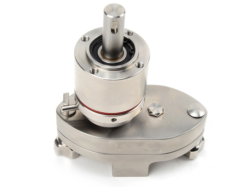
Assembly validation is strongest when the CNC prototype is inspected and tested with controlled mating parts, hardware, torque, orientation, and acceptance criteria. Consider an aluminum control housing with locating holes, a seal groove, and a thin internal cavity. The locating pattern may pass inspection from one setup, yet a datum transfer or wall movement after unclamping can shift the assembled position. Deburring can affect an internal edge, and anodizing can change final clearance at the bore or groove. The useful evidence is therefore the final-state inspection plus assembly and leak-test result, followed by a recorded decision to release, revise the datum scheme, adjust allowance, or rebuild.
Common CNC Prototype Validation Scenarios
Fit Check
A fit check should answer a defined interface question, such as whether a housing locates on two pins while clearing adjacent hardware in the final surface condition. Use the controlled mating parts and identify which component owns each datum and clearance. Record fastener size, insertion direction, torque or restraint when it affects alignment, and whether the prototype was inspected before or after finishing. A successful hand assembly alone does not identify the available margin or the source of interference. Pair the build result with measurements of the controlling interfaces and a disposition for any selective fitting or deviation.
Functional Testing
Functional testing evaluates a named response under controlled conditions rather than treating normal operation as proof of the complete design. The response may be leakage at a specified pressure, movement through a defined travel, thread retention under an approved torque, or thermal contact at a stated interface. Test fixtures, mating components, preload, environment, duration, and acceptance criteria belong in the plan. If prototype stock or machining differs from the production route, explain how that difference could affect the result. A pass supports only the tested configuration and revision; a failure should be traced to design, manufacture, assembly, or test before a change is authorized.
Surface Review
Surface review must distinguish appearance, texture, edge condition, and functional surface performance. A visual standard cannot substitute for a roughness requirement on a seal or sliding interface, while a roughness value alone does not define color, gloss, directional tool marks, or acceptable handling marks. Identify the surface location, condition, process stage, comparison method, and lighting or contact requirement that affects acceptance. Review machined edges after the planned deburring operation and inspect bores, threads, and grooves after coating when the finish changes dimensions. The result should state whether the surface is approved for function, appearance, both, or neither.
Validation Scenario | What the Team Checks | Why CNC Is Useful | Typical Part Type |
|---|---|---|---|
Datum-based fit check | Locating pattern, mating clearance, final-state dimensions, and controlled assembly result | Machined datums can connect inspection evidence to the actual interface | Housing: reject if datum transfer or unclamped wall movement consumes the fit margin |
Seal or motion test | Specified load, pressure, travel, mating parts, environment, and acceptance response | Functional faces, grooves, threads, and seats can be produced in a controlled state | Valve or mechanism: separate design failure from assembly or test-fixture error |
Finished-surface review | Location-specific appearance, texture, edge condition, and post-finish clearance | Machining and the planned secondary process can be reviewed as a sequence | Visible cover or contact part: approve cosmetic and functional criteria separately |
Production-transfer review | Material route, fixture, setup, tool access, deburring, finish, inspection, and open deviations | The prototype exposes route-specific risks that can be assigned before a pilot build | Complex component: transfer demonstrated variables and revalidate changed conditions |
Surface Quality and Tolerance Expectations for CNC Prototype Parts
Tolerance and surface expectations for CNC prototype parts must be specified by function, material condition, geometry, datum system, setup route, final finish, and measurement plan. There is no single defensible tolerance or roughness range for every prototype. A short rigid feature, a deep bore, and a thin wall respond differently to cutting and restraint. Surface roughness, waviness, lay, burr condition, and cosmetic appearance also describe different characteristics. The drawing or inspection plan should identify the controlled characteristic, its location, the applicable part state, and the method used to decide acceptance.
Prioritize evidence where an error would change the design decision: locating datums, seal faces and grooves, bearing or press fits, threaded interfaces, and wall conditions that influence assembly. Confirm whether a feature is measured free or restrained and whether acceptance applies before or after anodizing, plating, passivation, blasting, or another secondary process. Measurement resolution alone does not establish suitability; access, fixturing, uncertainty, sampling, and datum simulation must support the requirement. The supplier and buyer should resolve ambiguous datums, surface callouts, and acceptance rules before machining rather than interpreting them after a result fails.
How Fast Can CNC Prototypes Be Delivered?
CNC prototype delivery is controlled by the longest dependent path through design release, material confirmation, programming, workholding, machining, secondary processing, inspection, buyer review, and shipment. A simple-looking part can wait on unusual stock, an unresolved drawing, or outside finishing; a geometrically complex part can move predictably when authority and resources are settled. A credible schedule therefore lists dependencies and owners instead of promising one standard number of days. Request separate dates for drawing freeze, material availability, first-piece evidence, outside-process return, final inspection, and shipment when those events control the test program.
The RFQ can shorten avoidable delay by identifying the current revision, quantity, material and allowed substitutions, critical characteristics, finish state, inspection deliverables, test priority, and required arrival date. If only part of the quantity is needed for an early assembly check, state which configuration and evidence must accompany that shipment. Do not accelerate by silently removing final-state inspection or substituting material that changes the test conclusion. When a revision changes after work begins, reassess affected stock, programs, fixtures, outside processes, inspection plans, and dates before accepting the new schedule.
From CNC Prototype to Low-Volume Production
A CNC prototype can move into low-volume manufacturing without a complete process restart only when the approved evidence represents the proposed production route. Compare the controlled revision, material and stock form, machine and setup strategy, workholding, critical tools, deburring, finish supplier, inspection method, sampling, and accepted deviations. Any changed variable that can alter a critical result needs a documented review and, where necessary, a representative pilot or partial revalidation. Prototype approval by itself is not evidence of repeatable output across a production quantity.
Create a transfer decision for each critical characteristic. Mark it demonstrated when the prototype route and evidence remain applicable, conditionally transferable when a known change has a defined verification action, or open when the production route does not represent the prototype. Temporary fixtures, manual fitting, selected parts, concessions, and extra inspection must be visible because they can hide an unstable process. The low-volume release package should include the frozen authority, route changes, critical inspection and functional results, reaction plan, and triggers for renewed validation after material, fixture, tooling, finish, or design changes.
Conclusion
A CNC prototyping service validates design before production when the machined part and test plan represent the variables behind a specific release decision. CNC evidence is especially useful for datum-related geometry, machined interfaces, controlled material conditions, assembly fit, and final-state functional surfaces. It does not automatically validate a different stock form, manufacturing route, finish state, fixture, or repeatable production capability.
Before placing the RFQ, compare the dedicated CNC machining prototyping scope with the broader CNC machining services route and the intended low-volume manufacturing plan. Submit the controlled revision, exact material condition, critical datums and interfaces, final finish, inspection deliverables, mating parts, test conditions, and acceptance rules. Release the next stage only after each assumption is linked to evidence, an unresolved limitation, and a named approve, revise, rebuild, or revalidate decision.
FAQ
What Is a CNC Prototyping Service and When Should It Be Used in Product Development?
When Is CNC Prototyping Better Than 3D Printing for Functional Part Validation?
What Tolerances and Surface Quality Can CNC Prototype Parts Achieve?
How Fast Can a CNC Prototyping Service Deliver Parts for Engineering Testing?
Can CNC Prototype Parts Be Transitioned Directly into Low-Volume Production?