What Tolerances and Surface Quality Can CNC Prototype Parts Achieve?
What Tolerances and Surface Quality Can CNC Prototype Parts Achieve?
CNC prototype parts can achieve high dimensional accuracy and very good surface quality when the design, material, machining process, and inspection plan are matched correctly. In practical product development, prototype parts are not limited to rough evaluation models. They are often used for structural testing, functional validation, sealing checks, thread verification, and assembly confirmation, so the tolerance and finish level can be close to production requirements on the features that matter most.
For many prototype projects, general machined features are often controlled in a practical range such as ±0.01 mm to ±0.05 mm depending on geometry, material, and feature type, while selected critical surfaces or diameters may require tighter control through better workholding, refined toolpaths, or secondary finishing. Surface quality also varies by process stage. An as-machined finish can already be suitable for many engineering checks, but smoother and more specialized surfaces can be achieved through grinding or post-processing when the prototype must represent the final-use condition more closely.
1. Prototype Parts Can Still Achieve High Precision, Not Just Basic Shape Validation
One common misunderstanding is that prototypes only need approximate geometry. In reality, many CNC prototypes are built specifically to verify real mechanical fit, load path, motion, sealing, or hardware engagement. That means prototype parts often need accurate hole locations, thread quality, bore size, flatness, and datum relationships, not just a rough external outline.
This is why CNC prototyping is often chosen instead of simplified concept modeling when the team needs an engineering answer rather than a visual reference. A machined prototype can reproduce real pockets, slots, threads, faces, and interfaces with far better dimensional realism than a simplified mockup.
Prototype Objective | Typical Precision Need | Why It Matters |
|---|---|---|
Visual concept review | Lower | Main focus is form and packaging |
Assembly validation | Medium to high | Hole position, fit faces, and stack-up must be realistic |
Functional validation | High | Threads, bores, sealing surfaces, and motion features affect test results |
Pre-production engineering verification | High | Prototype may need to reflect final-use performance closely |
2. What Tolerance Levels Are Typically Practical for CNC Prototype Parts?
For CNC prototype parts, tolerance capability depends on the actual feature rather than a single universal number. General machined dimensions on stable geometry are often held in a practical range around ±0.01 mm to ±0.05 mm. Simpler block, plate, bracket, and turned features often stay closer to the tighter side of that range when the material is stable and the process is straightforward. More complex pockets, thin walls, long unsupported features, and difficult materials usually push the practical result toward the wider side of the range.
For critical prototype features such as locating bores, sealing diameters, precision slots, or datum-related hole patterns, suppliers may apply tighter control through reduced stock allowance, refined finishing strategy, in-process checks, or secondary refinement. The important point is that prototype accuracy can be very high, but it should be targeted where it creates engineering value rather than applied unnecessarily to every feature.
3. Surface Quality on Prototype Parts Can Also Be Very Good
Surface quality on CNC prototypes is often better than many buyers expect, especially compared with concept-only models. A well-machined prototype can deliver clean faces, controlled edges, stable bores, and visually acceptable external surfaces that are suitable for assembly review, handling tests, or product demonstration. This makes CNC prototypes valuable not only for measurement, but also for evaluating how the part feels, mounts, seals, or interacts with hardware.
However, surface quality is not only about appearance. It also affects function. A smoother bore may improve bearing fit, a flatter face may improve sealing, and a cleaner edge may improve assembly and safety. That is why prototype surface requirements should be linked to the specific engineering purpose of the part.
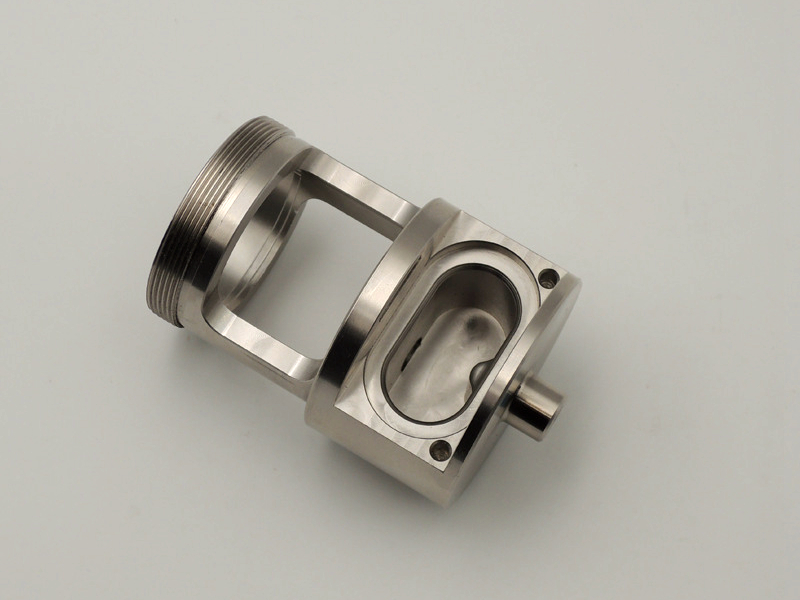
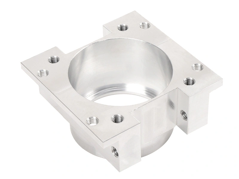
4. Why Complex Geometry Makes Tolerance and Surface Quality Harder to Control
Complex structure is one of the biggest factors affecting both tolerance capability and surface finish. Deep pockets, thin walls, long tool reach, narrow slots, multiple-sided setups, and fine-detail features all make the machining process less rigid and more sensitive to tool deflection, vibration, heat, and workholding variation. As complexity rises, the part may still be machinable, but controlling size and finish becomes more demanding.
For example, a simple flat plate with drilled holes is much easier to hold tightly than a thin-wall aluminum housing with deep cavities and multiple datum-related features. The second part needs more careful sequencing, lighter finishing passes, and stronger inspection discipline to achieve the same apparent precision level.
Geometry Type | Typical Precision Stability | Main Challenge |
|---|---|---|
Simple plate or bracket | Higher | Low setup complexity and strong rigidity |
Basic turned shaft | Higher | Good concentric process control on simple geometry |
Thin-wall housing | More difficult | Deflection, stress release, and heat response |
Deep pocket or multi-face complex part | More difficult | Tool reach, vibration, and multiple setup alignment |
5. Material Choice Also Changes the Result
Material has a major effect on prototype tolerance and surface quality. Softer and more machinable metals such as aluminum and brass often allow efficient cutting and good finish, but thin sections may still deform if support is limited. Stainless steel can deliver strong dimensional stability in service, but it creates more heat and can be more difficult to finish cleanly if the process is not well controlled. Harder steels may resist deformation better, yet tool wear and surface integrity become more important. Engineering plastics may machine well, but thermal expansion and local heat can influence stability on thin features.
This means the same nominal tolerance may be routine in one material and much more challenging in another. Prototype parts should therefore be evaluated as a combination of geometry, material, and process rather than by drawing number alone.
6. Machine Capability and Process Control Have a Direct Impact
The capability of the machine tool and the surrounding process plan strongly affect what a CNC prototype can achieve. Rigid machines, stable fixtures, controlled cutting tools, and a well-planned roughing-to-finishing sequence all improve the final result. Even a good material and a practical design can still produce poor tolerance stability if the setup is weak or the cutting strategy is too aggressive.
This is why prototype precision is not only about the machine’s advertised accuracy. It is also about workholding strategy, tool condition, datum transfer, inspection discipline, and whether the supplier understands how to cut the specific part without introducing unnecessary stress or distortion.
7. What Is the Difference Between As-Machined and Post-Processed Surface Quality?
An as-machined finish is the surface left directly by the final cutting operation. For many prototype uses, this is already good enough to validate fit, structural behavior, assembly interfaces, and many functional conditions. It reflects the real machining process and is often the best starting point when the team wants to understand the actual part condition before added finishing steps.
Post-processing changes that surface after machining. Depending on the application, this may involve finer surface refinement, visual enhancement, corrosion resistance improvement, or a more production-like appearance. For aluminum prototypes, anodizing may be used when the team wants to evaluate coated appearance or added corrosion protection. For stainless prototypes, electropolishing may be chosen when smoother functional or visual surfaces are needed. The key difference is that as-machined represents the direct machining result, while post-processing adds another layer of surface performance or appearance control.
Surface Condition | Main Use | Typical Value in Prototyping |
|---|---|---|
As-machined | Fit, function, machining realism, engineering validation | Shows the real machining result before extra treatment |
Ground or refined surface | Higher precision contact or finishing control | Useful for critical bores, diameters, or high-precision faces |
Post-processed surface | Appearance, corrosion resistance, or smoother final-use condition | Useful when prototype must reflect more of the final product state |
8. When Is Grinding Used on Prototype Parts?
CNC grinding is typically used on prototype parts when the feature needs better dimensional refinement or smoother contact quality than milling or turning alone can provide economically. This may apply to bearing surfaces, sealing diameters, guide surfaces, hardened contact areas, or parts where the prototype must validate a very controlled finish condition.
Grinding is usually not necessary on every prototype, but it becomes important when the team is validating a feature that depends directly on roundness, contact behavior, or fine surface quality. In those cases, the prototype is no longer just a geometric test piece. It is functioning as a near-final engineering component.
9. How Should Buyers Judge the Right Prototype Precision Level?
Buyers should define prototype precision based on the purpose of the test rather than requesting maximum tightness everywhere. If the prototype is mainly for general form review, moderate tolerance and standard as-machined finish may be enough. If it is for assembly validation, the mating features and mounting datums should be controlled more tightly. If it is for functional testing, bores, threads, sealing faces, and critical contact areas may need much higher accuracy or better surface refinement than the rest of the part.
This selective approach keeps prototype cost practical while still making the test meaningful. It also prevents the project from overpaying for precision on non-critical features that add little engineering value.
10. Summary
In summary, CNC prototype parts can achieve high accuracy and strong surface quality when the design, material, machine capability, and process plan are aligned correctly. Prototype parts are fully capable of supporting real engineering validation, and selected critical features can often be controlled to a very high level when needed. However, the final result always depends on geometry complexity, material behavior, workholding stability, and the precision strategy chosen for the part.
An as-machined finish is often sufficient for many prototype goals, while grinding and surface post-processing such as anodizing or electropolishing can be added when the prototype must reflect more demanding functional or final-use conditions. The best prototype quality level is therefore the one that matches the real validation objective, not simply the tightest possible number on every feature.