Standard Machine Finish: Surface Expectations, Measurement, and Cost Tradeoffs
Standard Machine Finish: Surface Expectations, Measurement, and Cost Tradeoffs
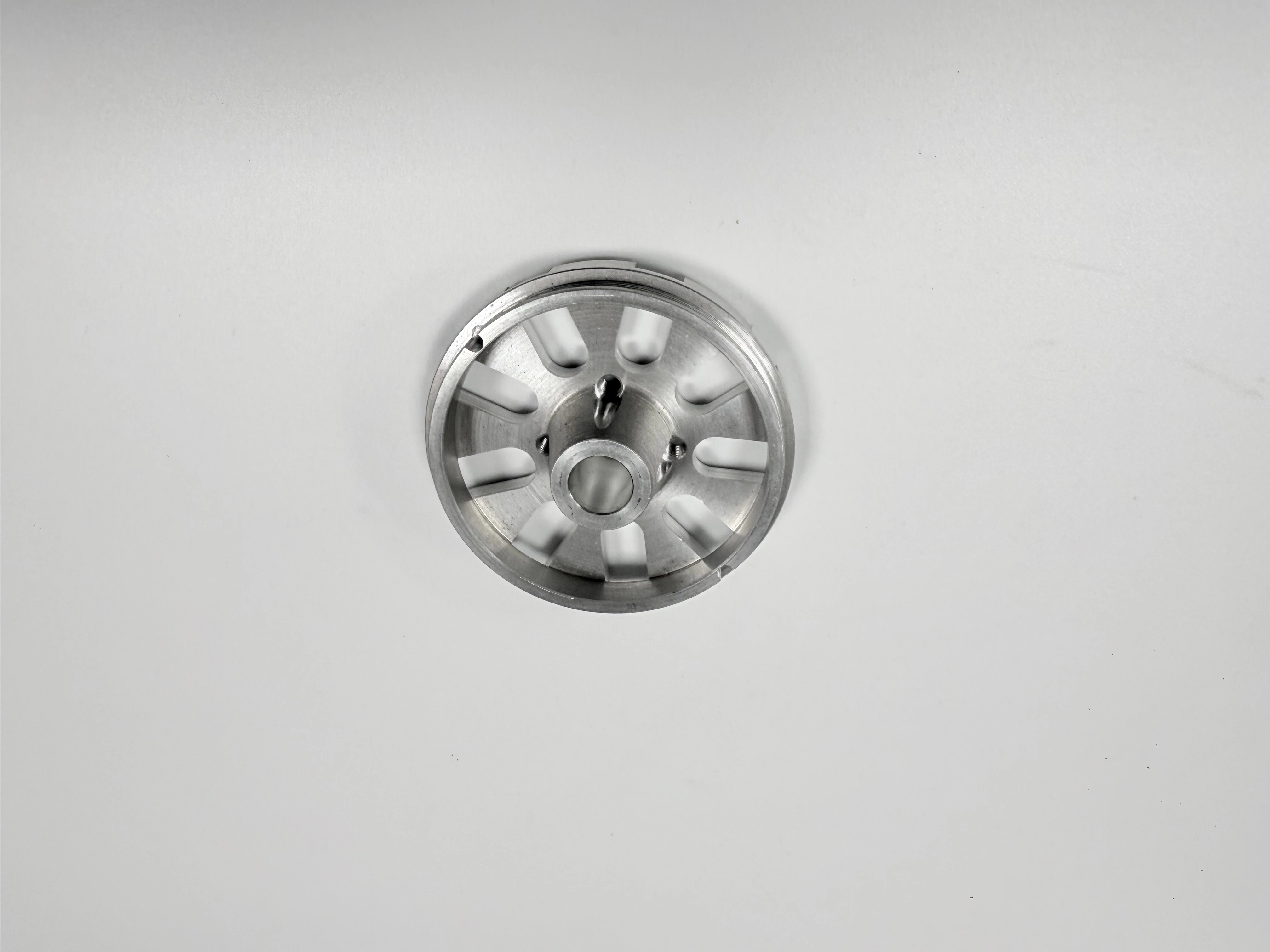
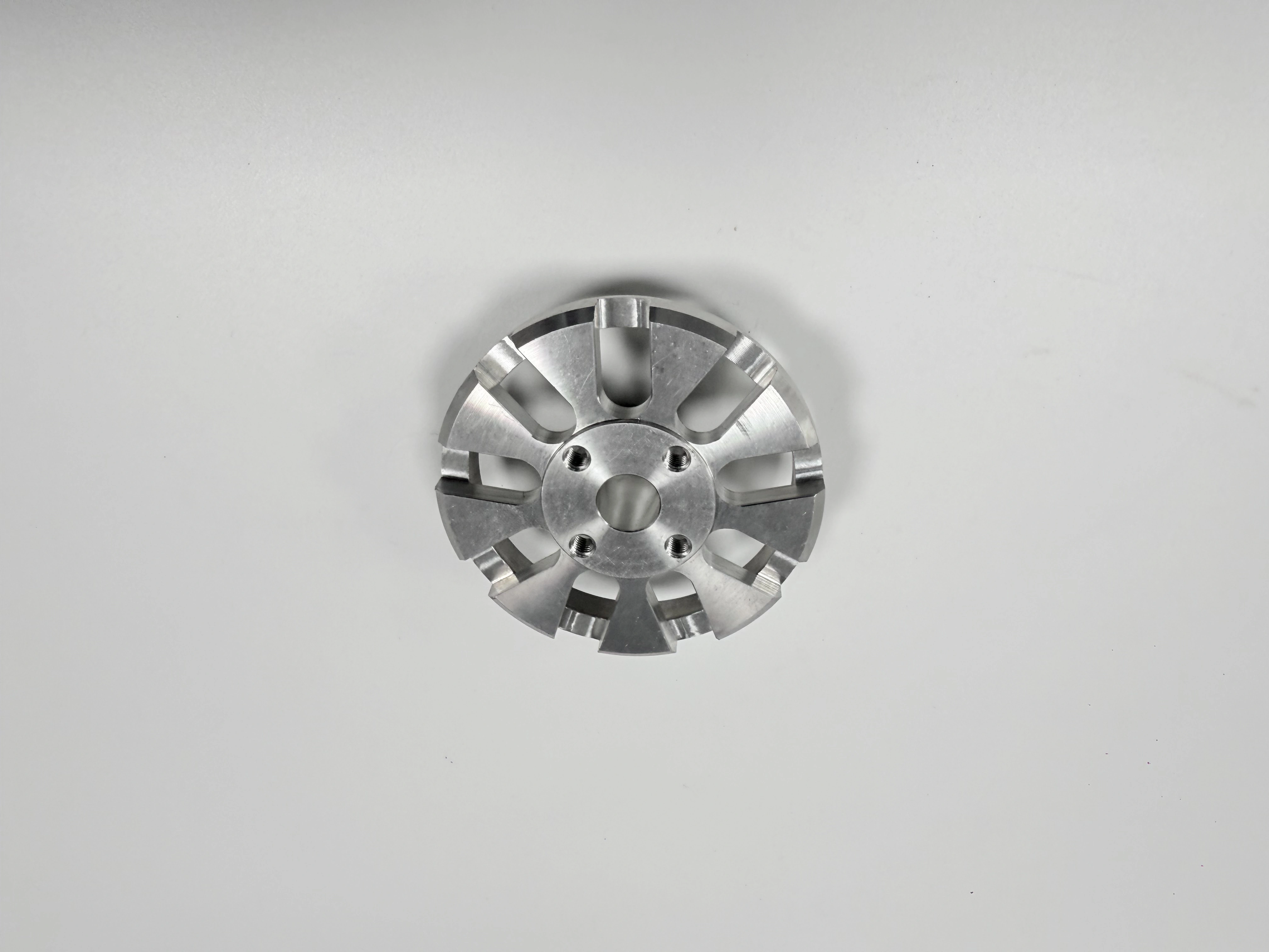
Standard machine finish is an acceptance boundary, not a universal roughness guarantee. Buyers should define the functional surface, visible texture, burr and edge state, measurement method, material and process condition, and any later coating before comparing a machined-part quote. The pictured round face part shows a central opening, radial grooves, and an outer rim from two views. Those images support geometry and visible texture only; they cannot prove roughness values, material, tolerance, or service performance. A surface-finish planning review helps connect appearance to measurable requirements.
Define the Finish Before Quoting
Write the finish requirement in terms of function and evidence. A sealing face may need a measured texture and direction, a locating face may need burr control and flatness, and a cosmetic face may need a visual reference. “Standard machine finish” should not be used to hide an unspecified roughness, edge break, tool-mark direction, or cleaning state. Identify the surface, requirement, method, sampling, and delivered condition.
Use a surface register that names each face, groove, opening, rim, or edge and states why it matters. A part can have a smooth central face and a rough groove that still performs correctly if the groove is nonfunctional, while a lightly marked sealing land may fail. The register prevents a single global finish label from masking different acceptance decisions. It also tells a supplier where additional passes or measurements are justified.
Define how the finish requirement interacts with geometry. Removing stock to improve texture can change a shoulder, opening, or runout relationship. A coating can cover texture but add thickness. A cleaning step can remove oil that had hidden a burr. State the order of operations and the characteristic that must be rechecked after each state change.
Separate as-machined, deburred, cleaned, coated, and assembled states. Each state can change texture, dimensions, contamination, or appearance. Record which state is accepted and which measurements repeat after an outside process. A quality inspection reference can structure the report fields, but the drawing and acceptance plan control the part.
Record the acceptance owner and the point at which the finish decision is made. This prevents a supplier from closing a surface question during machining while the buyer evaluates a coated or assembled state.
Keep this boundary beside the inspection result and the packing record.
That link between surface, state, and evidence is what makes a finish repeatable.
Use the Round-Part Views as a Texture Prompt
The paired images show one circular machined part with a central opening, radial grooves, and an outer rim from different angles. They confirm the same physical product and different views. They do not reveal roughness numbers, alloy, hardness, tolerance, coating, spindle path, or function. Use the views to ask where tool marks, burrs, and inspection access may matter; use controlled records for every engineering conclusion.
Separate Functional and Cosmetic Surfaces
Classify each surface as sealing, sliding, locating, clamping, thermal, cosmetic, or nonfunctional. A polished appearance may still hide a wrong shoulder or runout, while a visible tool path may be acceptable on a nonfunctional face. State the direction, area, and condition of a functional surface. If appearance is the only requirement, define a reference sample, lighting, viewing distance, and permitted marks.
On a round face part, the central opening, groove flanks, radial channels, and outer rim may serve different purposes. Do not apply one finish expectation to every surface. A turning reference can frame face and groove operations, but it cannot establish the functional finish without the drawing and mating context.
Specify Roughness Measurement
When a numeric roughness requirement matters, state the parameter, direction, cutoff, filter, sampling length, instrument, and acceptance basis. A reading on a flat face may not represent a groove, bore, or curved rim. Record whether the surface is measured dry, oiled, coated, or cleaned. Do not convert a visual match in the images into a numeric guarantee.
Check instrument suitability and calibration. A result near a limit should trigger repeat readings and review of stylus direction, support, temperature, and contamination. Preserve raw traces or values and identify the unit. Rounding a borderline result can conceal variation. A roughness value also does not prove flatness, hardness, or fatigue performance.
Understand Tool-Path Texture
Tool geometry, feed, speed, step-over, depth of cut, tool wear, coolant, support, and material condition influence visible texture and measured roughness. State which variables are controlled and which are allowed to vary. A standard finish may come from a roughing operation, a finishing pass, a face mill, a turning tool, or a blended method. The operation name alone does not define the delivered surface.
Consider direction as well as magnitude. A directional tool path may be acceptable on a cosmetic face but can affect sealing, sliding, optical reflection, or chip retention on a functional face. State the measurement direction and any orientation restriction in the drawing or process note. If a surface is rotational, identify whether the stylus or scan follows or crosses the lay. A numeric value without direction can be difficult to interpret.
Review transitions between operations. A groove bottom may be cut with one tool and its rim with another, leaving a blended band or burr at the boundary. A reversal can create a witness line that is acceptable visually but not on a seal. Mark transition zones in the inspection plan and state whether they are functional. Do not call an entire face uniform when only one region was measured.
For radial grooves, consider tool entry and exit, burr direction, groove bottom access, and the way a probe or stylus crosses the texture. A milling reference can help compare face and groove strategies, while a CNC process reference can organize variables. Neither proves a specific result for the pictured part.
Control Tool Wear and Change Points
Tool wear can increase roughness, burrs, dimensional drift, and heat. Define a tool identifier, life limit or inspection trigger, offset policy, and reaction to a texture change. If a tool is replaced during a small lot, mark the affected units and repeat sensitive measurements. A stable first piece under one tool state does not release units made after an undocumented change.
Preserve tool, program, coolant, and setup records with the lot. A low roughness result from a fresh tool may not represent the worn state used later. If the buyer wants a standard finish without a numeric requirement, the supplier should still state the visual or process boundary and how it is checked.
Control Burrs and Edge Breaks
Deburring is part of finish acceptance when a burr can cut, interfere, trap contamination, or alter a locating surface. Define edge break, radius, burr direction, accessible edges, and the method. Manual work can remove material unevenly from a groove or opening. An edge that looks smooth may still be too large for a mating feature; a measured edge break may be acceptable even if texture remains visible.
Inspect edges before and after cleaning, coating, and assembly when those steps affect the decision. Record visual references and dimensional or functional checks. A deburring reference can frame process options, but actual acceptance remains tied to the controlled requirement.
Protect Grooves and Recesses
Grooves and recesses may retain chips, resist a stylus, or receive uneven deburring. State width, depth, corner radius, bottom condition, cleaning, and inspection access where functional. If a groove carries a seal or snap ring, include the mating condition. A visual view from above cannot prove the bottom or sidewall state. Use a section, gauge, or alternate method with a defined boundary.
Account for Material and Thermal State
Material designation, hardness, temper, stock condition, heat treatment, residual stress, and temperature affect tool wear, texture, burrs, and dimensional stability. Specify the required condition and certificate. Do not infer alloy or hardness from the image. If a substitute is proposed, identify which finish and geometry conclusions transfer and which require a new trial.
Define measurement temperature, stabilization, cleaning, and delivered state. A warm part or oil film can report a different roughness or fit than a stabilized clean part. If coating or plating follows machining, record specification, processor, batch, masking, before-and-after dimensions, and repeat surface checks. A material reference can support the RFQ but cannot certify this part.
Separate Coating From As-Machined Finish
A coating can cover tool marks, change texture, fill a groove, or alter a fit. State whether the standard finish applies before or after coating and which surfaces are masked. Record coating batch, thickness method, adhesion or appearance requirement when relevant, and delivered-state inspection. Do not call a coated surface “as machined” without a clear boundary.
Inspect Texture With Context
Build the inspection plan around the function at risk. Measure roughness where it controls sealing or sliding, flatness where a face locates, runout where a circular surface rotates, and burr or edge where assembly can be damaged. Use a suitable instrument and state support, direction, section, temperature, cleaning, and unit. One roughness reading cannot prove every surface on the part.
For the round face part, measure central opening, face runout, groove condition, outer rim, and selected texture locations separately. A CMM inspection reference can frame geometry, while a roughness trace or comparison sample supports surface evidence. Keep the methods distinct and state inaccessible areas.
Use a reference sample only when its material, process state, lighting, and viewing condition are controlled. A visual comparator can support appearance, but it cannot prove a numeric roughness or hidden groove condition. Record who compared the surface, under what light, and what features were reviewed. If different operators disagree, define a measured method or an approved reference rather than averaging opinions.
Check the instrument footprint and access. A stylus may not reach the bottom of a narrow groove, and a probe may bridge a radius. An optical method can be sensitive to reflectivity or oil. Record the accessible region and any excluded area. If an alternate method is used, explain how it relates to the requirement and retain the limitation in the release record.
Choose Sampling From the Surface Risk
Every-unit inspection may be justified for a small lot when one burr or rough groove can prevent assembly. Sampling can be appropriate for lower-risk cosmetic surfaces after a stable state is shown. A tool replacement, material lot, setup reversal, coolant change, or outside-process batch creates a new state that needs its own first piece or sample. Link values to unit or sub-lot identity.
If a surface fails, preserve the original result and identify the reaction: containment, controlled deburring, tool change, expanded inspection, replacement, deviation, or new trial. Rework can alter a groove or edge. Record the original and new value, approver, and affected range. Do not overwrite a failed reading.
Evaluate Finish Cost Without Hiding Scope
Separate programming, tooling, finishing passes, deburring, inspection, cleaning, coating, packaging, and engineering changes. A numeric roughness requirement may add measurement time or a finishing operation. A visual standard may reduce measurement but require a reference sample and consistent lighting. A low price can hide an omitted check or an undefined delivered state.
Ask suppliers to state quantity breaks and the conditions behind them. A higher quantity may use a dedicated tool, a different fixture, a reduced sample, or an outside processor. Keep those assumptions visible. Do not treat a unit discount as proof that a standard finish is stable across every batch.
Compare the cost of prevention with the cost of detection. A controlled finishing pass may reduce roughness variation, while a broader inspection plan may only discover it after machining. A reference sample can reduce instrument time but requires agreement and training. Show the line that changes when the quantity or risk changes. The decision is not always the lowest finishing charge; it is the lowest defensible total for the required surface state.
Write the Finish RFQ
Provide drawing and model revisions, functional surfaces, roughness or visual requirements, edge and burr criteria, material and stock, operation boundary, inspection method, sample, outside processing, packaging, records, and change authority. Ask for the proposed tool and process assumptions, first-piece format, reaction to a failed surface, and delivered-state check. A production planning reference can frame milestones, but the finish definition must remain part-specific.
State what the images show and do not show. The round face views support grooves, opening, rim, and visible texture. They do not prove roughness values, material, tolerance, coating, or performance. This boundary keeps a supplier quote tied to evidence rather than appearance.
Screen Suppliers for Surface Evidence
Compare whether each supplier can explain tool state, finish operation, deburring, measurement direction, instrument, sample, material trace, outside-process handoff, and reaction rules. A machine list or phrase such as “standard finish included” is not evidence. Prefer a response that identifies assumptions, owners, limits, and the record delivered with the lot.
Ask suppliers how they maintain surface identity when parts move between machining, washing, coating, and packing. A supplier may measure an accessible face and assume the groove follows it, or may mix units after a tool change. Request a state map and the unit range for each record. This evidence is more useful than a general claim about polished or smooth results.
Protect Finish Through Handoff
Define cleaning, separators, corrosion protection, labels, and receiving inspection. A textured face can collect chips, and an unprotected rim can be scratched in transit. Link packaging and receiving records to unit identity and the finish state accepted. A packaging reference may help organize questions, but it does not replace the receiving criteria.
Release the Standard Finish With Boundaries
Release when functional surfaces, visual or numeric finish requirements, burr and edge state, material, process, inspection, outside processing, packaging, and approvals agree. Hold when “standard” is undefined, a roughness reading lacks direction or state, a groove is inaccessible, a tool change is untracked, or the delivered surface differs from the accepted condition. State the missing evidence and owner.
Standard machine finish is useful when it tells the supplier and buyer exactly what is accepted and how it is checked. The paired images support only visible geometry and texture. Let the drawing, material record, tool and setup state, surface measurements, and receiving check determine whether to accept, revise, or add a finishing operation.
Keep the final statement tied to the inspected face, state, sample, and method so a later order can be compared without expanding the original claim.
FAQ
How Should Standard Machine Finish Be Defined for Functional Surfaces?
Which Roughness Evidence Is Useful for a Machined Round Face?
How Should Deburring and Edge Breaks Be Specified in a Finish RFQ?
How Can Buyers Compare Machine-Finish Quotes and Inspection Scope?
What Records Support Repeat Orders With the Same Machine Finish?