Medición 3D por escaneo para piezas mecanizadas CNC de alta precisión
Más allá de la medición tradicional: cómo el escaneado 3D redefine la inspección de calidad de piezas CNC
En la fabricación de precisión, el control de calidad es siempre la clave para garantizar el rendimiento del producto. Como ingenieros de medición en Neway, hemos sido testigos de la evolución revolucionaria de la metrología en la última década. Aunque las máquinas de medición por coordenadas (CMM) tradicionales son fiables en cuanto a precisión, su enfoque de medición por contacto y en puntos únicos resulta cada vez más insuficiente frente a las complejas piezas de geometría libre actuales. La tecnología de escaneado 3D, con su alta eficiencia y capacidad de adquisición de datos de campo completo, está redefiniendo los estándares de calidad para la inspección de piezas mecanizadas por CNC.
En la manufactura moderna, a medida que las geometrías de los productos se vuelven más complejas, los requisitos para el mecanizado de precisión han pasado de una simple exactitud dimensional a la precisión global de forma y superficie. El escaneado 3D puede capturar en cuestión de minutos una enorme nube de puntos de la superficie de la pieza, lo que permite una inspección de tamaño completo al 100%. Este enfoque no solo mejora la eficiencia de la inspección en varios órdenes de magnitud, sino que también identifica desviaciones localizadas que los métodos tradicionales pueden pasar por alto, proporcionando una perspectiva de control de calidad excepcionalmente completa.
El núcleo de la tecnología de escaneado 3D: explicación del láser y la luz estructurada
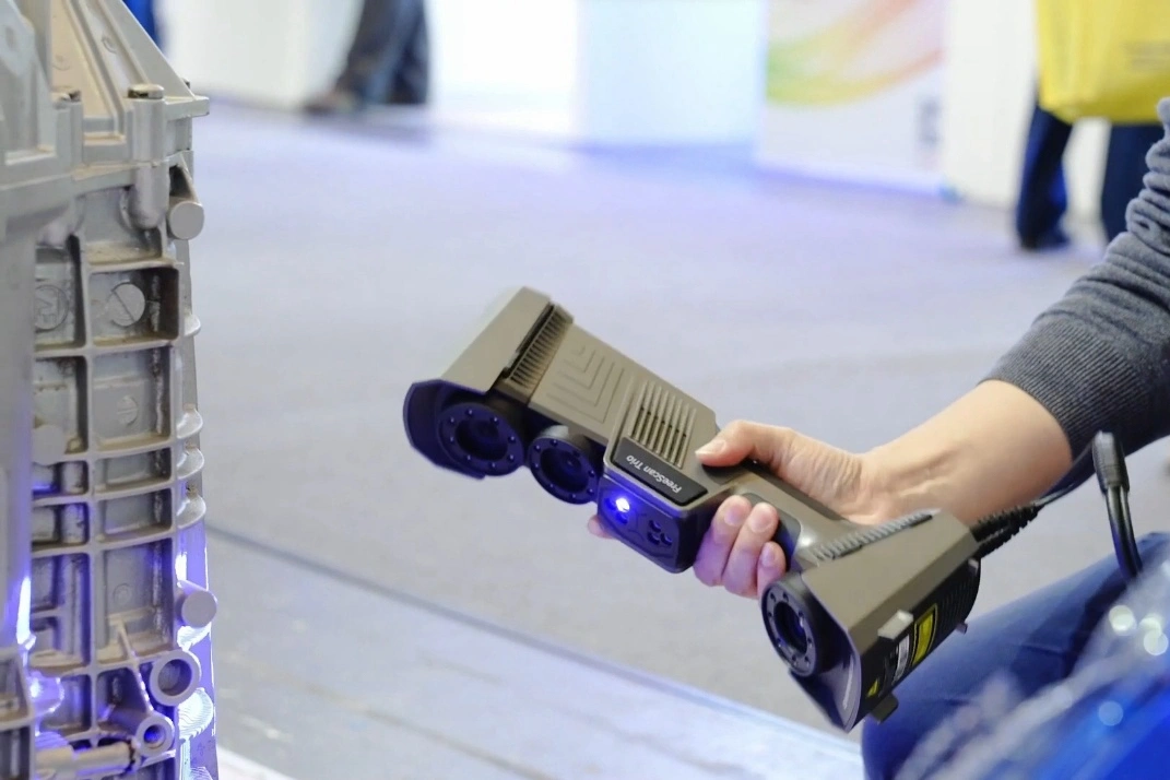
Escaneado láser: adquisición de nubes de puntos de alta precisión
La tecnología de escaneado 3D por láser se basa en la triangulación láser. El escáner proyecta una línea o un punto láser sobre la superficie de la pieza, y una cámara captura la luz reflejada. Calculando el desplazamiento de la mancha de luz en el sensor de la cámara, se determinan las coordenadas tridimensionales de la superficie. Este método ofrece una precisión muy elevada, llegando a niveles micrométricos, y es especialmente adecuado para piezas con abundantes detalles superficiales y características complejas. Nuestros escáneres láser manuales están equipados con marcadores de posicionamiento, lo que permite la alineación automática de datos desde múltiples ángulos y garantiza una cobertura y una integridad completas al medir componentes de gran tamaño.
Escaneado por luz estructurada: medición de superficie de campo completo y alta velocidad
El escaneado por luz estructurada utiliza un proyector para proyectar sobre la superficie de la pieza una secuencia de patrones de franjas codificados. Una cámara captura los patrones deformados por la geometría superficial, y mediante análisis de fase combinado con triangulación se reconstruye la forma 3D. Este método sin contacto es extremadamente rápido: un solo escaneado puede capturar millones de puntos de datos, lo que lo hace especialmente adecuado para grandes superficies curvas y piezas blandas o fácilmente deformables. En nuestras operaciones, el escaneado por luz estructurada se ha convertido en el método preferido para la inspección de primera pieza de componentes de geometría libre compleja producidos mediante mecanizado de ejes múltiples.
Escenarios de aplicación y comparación de precisión entre diferentes tecnologías de escaneado
Seleccionar la tecnología de escaneado adecuada es crucial para una medición precisa. El escaneado láser es más apropiado para agujeros profundos, superficies muy inclinadas y zonas con sombras ópticas pronunciadas, mientras que el escaneado por luz estructurada sobresale en superficies extensas y texturas finas. Nuestro laboratorio está equipado con ambos tipos de sistemas, lo que nos permite elegir la solución óptima en función del material, el estado superficial y los requisitos de tolerancia, garantizando así que nuestros clientes reciban los resultados de medición más precisos.
Cuatro aplicaciones clave del escaneado 3D en la fabricación CNC de alta precisión
Inspección de primera pieza (FAI) y generación de informes de dimensiones completas
El escaneado 3D ofrece ventajas extraordinarias en la inspección de primeras piezas. Comparando los datos de escaneado con el modelo CAD original en toda la superficie, podemos generar rápidamente mapas de colores intuitivos que muestran las desviaciones dimensionales en cada ubicación. Este método no solo reduce de forma significativa el tiempo de inspección, sino que, lo que es más importante, descubre desviaciones localizadas que los métodos tradicionales pueden pasar por alto, proporcionando un respaldo de datos completo para la optimización del proceso durante la fase de prototipado.
Medición precisa de superficies complejas y formas de geometría libre
Para piezas como álabes de turbina, impulsores y moldes de inyección con superficies complejas, la metrología tradicional tiene dificultades para evaluar por completo la calidad del mecanizado. El escaneado 3D captura con gran fidelidad sus perfiles superficiales reales, y posteriormente se emplea un análisis dedicado de desviaciones de superficie para verificar si la geometría fabricada se ajusta a la intención de diseño. En la industria aeroespacial en particular, este enfoque se ha vuelto indispensable para garantizar el rendimiento aerodinámico.
Análisis de fallos y diagnóstico de problemas de ensamblaje
Cuando las piezas presentan problemas de interferencia en el montaje o fallos funcionales, el escaneado 3D revela rápidamente la causa raíz. Escaneando las piezas problemáticas y sus componentes asociados, podemos crear un modelo digital de ensamblaje extremadamente preciso y analizar holguras e interferencias en un entorno virtual para identificar problemas de diseño o de fabricación. Este método ofrece una alta eficiencia de diagnóstico y evita pruebas de montaje repetitivas que podrían dañar las piezas.
Ingeniería inversa y optimización del diseño sin modelos CAD existentes
En proyectos que parten de muestras físicas, el escaneado 3D es la tecnología central de la ingeniería inversa. Los escaneos de alta precisión capturan toda la geometría 3D de la superficie de la pieza. Tras el procesamiento de la nube de puntos y la reconstrucción de superficies, podemos generar con rapidez modelos CAD adecuados para su reproducción o modificación. Esto es especialmente valioso para piezas de repuesto, componentes antiguos y actualizaciones de diseño, ya que proporciona una base geométrica sólida para la optimización.
Flujo de trabajo de escaneado 3D de Neway: desde la captura de datos hasta el análisis
Paso uno: preparación de la pieza y estrategia de escaneado
Antes de la medición, nuestros ingenieros revisan minuciosamente la función de la pieza, las características críticas y los requisitos de tolerancia. En función del tamaño, la geometría y el material, definimos la estrategia de escaneado óptima. Para superficies altamente reflectantes, como las de las piezas de aleación de aluminio, aplicamos un recubrimiento temporal mate. Para zonas oscuras, como los componentes de PEEK, ajustamos los parámetros de escaneado para garantizar la integridad de los datos.
Paso dos: adquisición de datos multiángulo y registro de nubes de puntos
En la práctica, realizamos escaneos desde múltiples ángulos para asegurar la cobertura completa de todas las superficies. Durante el escaneado, el sistema proporciona retroalimentación en tiempo real sobre las zonas ya cubiertas y las aún no capturadas, guiando al operador para rellenar las regiones faltantes. Para piezas de gran tamaño, utilizamos dianas de posicionamiento para garantizar la alineación precisa de los conjuntos de datos procedentes de diferentes vistas, manteniendo los errores globales de registro dentro de los 0,01 mm.
Paso tres: procesamiento de la nube de puntos y reconstrucción del modelo 3D
Tras capturar la nube de puntos bruta, la procesamos con software profesional, incluyendo reducción de ruido, depuración de datos y optimización. La nube de puntos refinada se convierte después en un modelo de malla 3D mediante triangulación. Este modelo preserva con precisión todas las características geométricas de la pieza y sirve como base para las evaluaciones posteriores.
Paso cuatro: comparación con CAD y análisis de mapas de color de desviaciones
El paso final y más crítico es la comparación precisa entre los datos de escaneado y el modelo de diseño. Tras una alineación de mejor ajuste, el software genera detallados mapas de colores de desviación que muestran las variaciones dimensionales en toda la superficie. También realizamos análisis GD&T para evaluar tolerancias de posición, de perfil y otras características geométricas de las zonas críticas, y podemos emitir informes de inspección de primeras piezas conformes con normas como AS9102.
El valor de los datos precisos: interpretación de informes de escaneado 3D y análisis de desviaciones
Los informes de escaneado 3D son una herramienta clave de comunicación entre nosotros y nuestros clientes. Los mapas de colores de desviación utilizan un código de colores para mostrar de forma intuitiva las diferencias entre la pieza real y el modelo CAD. Normalmente, el color verde indica zonas dentro de tolerancia, mientras que del amarillo al rojo representan desviaciones positivas, y el azul indica desviaciones negativas. Esta visualización permite a los clientes comprender rápidamente el estado global de calidad de sus piezas.
En el sector de dispositivos médicos, prestamos especial atención a la precisión de las superficies funcionales. Por ejemplo, la conformidad de las superficies articulares en implantes de articulaciones influye directamente en la vida útil del producto y en la comodidad del paciente. Mediante el análisis de escaneado 3D nos aseguramos de que cada implante de aleación de titanio coincida con precisión con la geometría superficial prevista.
En el caso de componentes complejos, como las carcasas de turbocompresores en la industria automotriz, utilizamos datos de escaneado 3D para evaluar la continuidad de los conductos de flujo internos y confirmar un rendimiento aerodinámico óptimo. Al mismo tiempo, examinamos con detenimiento la exactitud dimensional en las interfaces de montaje para evitar dificultades de ensamblaje o fallos de estanqueidad causados por desviaciones.
Casos de estudio en profundidad: retos reales de fabricación resueltos con escaneado 3D
Caso 1: verificación de la precisión del perfil de álabes de motor aeroespacial
Un cliente del sector aeroespacial nos encargó la inspección de un lote de álabes de turbina de alta presión fabricados en Inconel 718. El escaneado 3D reveló desviaciones sistemáticas de contorno en zonas específicas del perfil del álabe, con una desviación máxima de 0,08 mm. Un análisis posterior demostró que el problema se debía al desgaste de la herramienta durante el proceso de mecanizado. Con base en nuestro informe, el cliente ajustó los parámetros de corte y la gestión de la vida útil de las herramientas, evitando así un posible incidente de calidad a gran escala.
Caso 2: análisis de interferencias de ensamblaje en carcasas de turbina de turbocompresores
Un fabricante de automóviles informó de problemas de interferencia durante el montaje de carcasas de turbina de acero inoxidable con los componentes de la turbina. Mediante escaneado 3D obtuvimos modelos precisos de las piezas reales y realizamos simulaciones digitales de ensamblaje. El análisis mostró un error de planitud de 0,2 mm en la superficie de apoyo de la brida. Siguiendo nuestras recomendaciones, el cliente optimizó la estrategia de sujeción en el mecanizado de ejes múltiples, solucionando por completo el problema de interferencia.
Caso 3: evaluación de la conformidad superficial de implantes articulares médicos
Durante el desarrollo de un proyecto de prótesis de rodilla, utilizamos escaneado 3D para evaluar la conformidad de distintas superficies articulares de prototipos. Los resultados del escaneado indicaron que las holguras en ciertas zonas superaban los límites permitidos, lo que podía provocar un desgaste anómalo. A partir de estas conclusiones, el equipo de diseño perfeccionó la geometría de las superficies articulares, logrando una mejora significativa en el rendimiento clínico.
Ventajas clave de elegir a Neway para medición mediante escaneado 3D
En Neway, integramos el escaneado 3D de forma profunda en todo el proceso de fabricación, creando una ventaja competitiva única. Nuestros sistemas de escaneado se calibran periódicamente para garantizar precisión y trazabilidad. Aún más importante, nuestros ingenieros de medición no solo dominan las tecnologías de escaneado, sino que también conocen a fondo los procesos de fabricación, lo que les permite interpretar los datos desde una perspectiva de ingeniería y ofrecer recomendaciones de optimización prácticas.
En proyectos de producción de bajo volumen, el escaneado 3D permite una validación rápida de primeras piezas y plazos de entrega más cortos. En producción en masa, establecemos bases de datos de muestreo basadas en escaneos y realizamos análisis estadísticos de procesos para activar alertas tempranas de calidad. Nuestra filosofía de servicio integral (one-stop) garantiza un flujo de trabajo en bucle cerrado desde el escaneado y la inspección hasta la mejora del proceso.
También prestamos especial atención al impacto de los tratamientos superficiales en los resultados dimensionales. Por ejemplo, en piezas sometidas a granallado o arenado, evaluamos cómo la rugosidad superficial afecta a la precisión del escaneado; en componentes anodizados, tenemos en cuenta el espesor del recubrimiento en la evaluación dimensional. Este enfoque integral garantiza que nuestros resultados de medición reflejen con precisión la condición real de funcionamiento de la pieza.
Preguntas frecuentes (FAQ)
¿Cuál es la precisión máxima alcanzable en las mediciones por escaneado 3D?
¿Existen superficies específicas, como superficies oscuras o reflectantes, que puedan escanearse?
¿Es adecuado el escaneado 3D para piezas con estructuras internas complejas?
¿Cuánto tiempo suele transcurrir desde el escaneado hasta la recepción del informe de inspección?
¿Pueden utilizarse directamente los datos de escaneado 3D para generar programas de mecanizado CNC?
