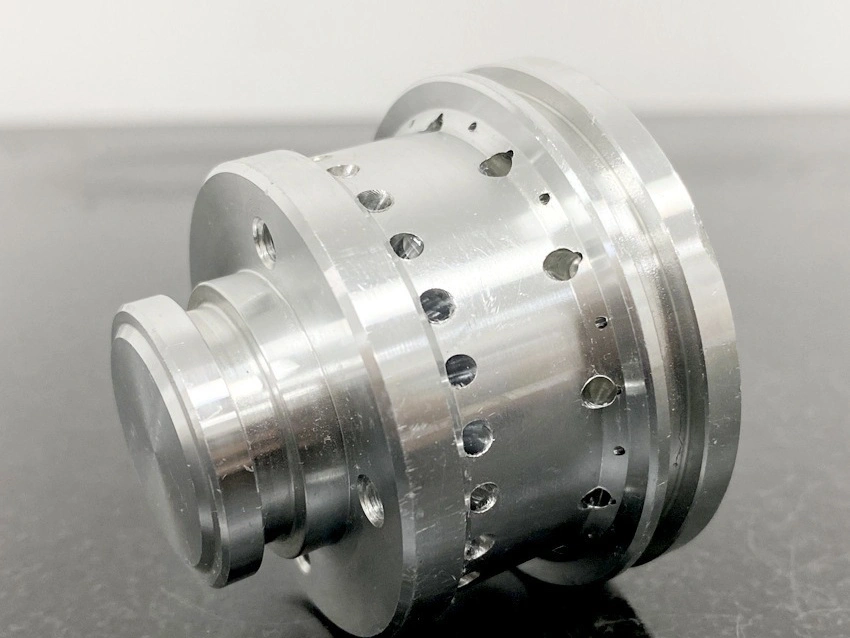
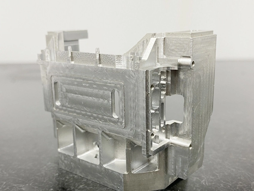
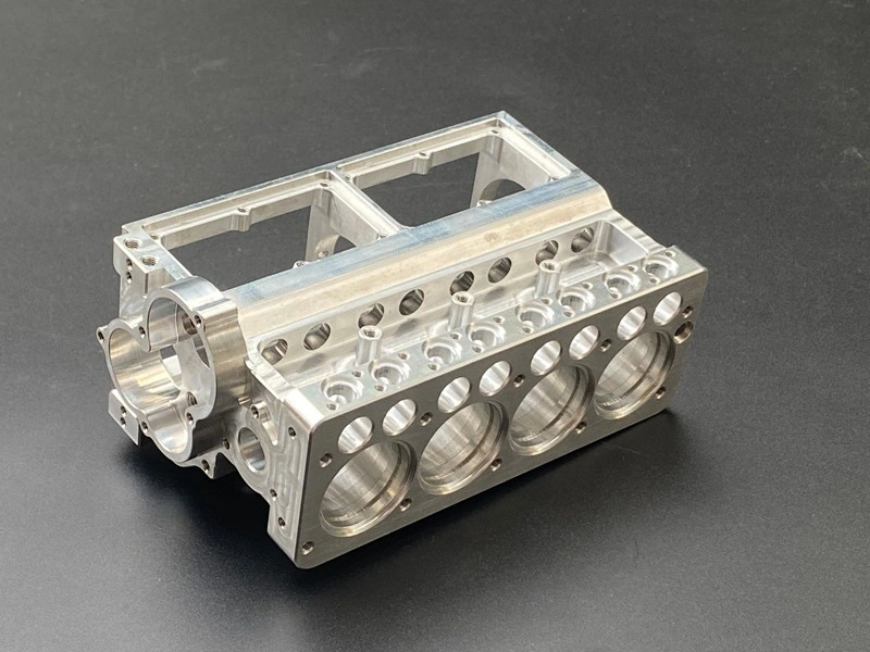
Precision Machining for Complex Custom Parts with Datum, GD&T, and Inspection Requirements
Precision Machining for Complex Custom Parts with Datum, GD&T, and Inspection Requirements
For many custom machined parts, the real challenge is not producing one difficult dimension. It is keeping multiple datums, multiple machined faces, and multiple geometric requirements aligned in a way that still supports final assembly. A part may appear acceptable if each local size checks out, but if the datum structure is misunderstood or the GD&T logic is not followed through the full process route, the part can still fail during assembly, sealing, rotation, or functional verification. That is why buyers sourcing precision machining for custom parts are often looking for more than machining capacity. They need a supplier that can read the drawing the way the design engineer intended it.
This is especially important for aerospace, medical, robotics, automation, energy, and fixture-related parts where location, orientation, and feature relationships matter more than isolated nominal dimensions. In these projects, precision machining is closely tied to datum control, process sequencing, fixture strategy, and inspection planning. The supplier must understand not just what the part looks like, but how the part is meant to function inside an assembly.
Why Datum Control Matters in Precision Machining
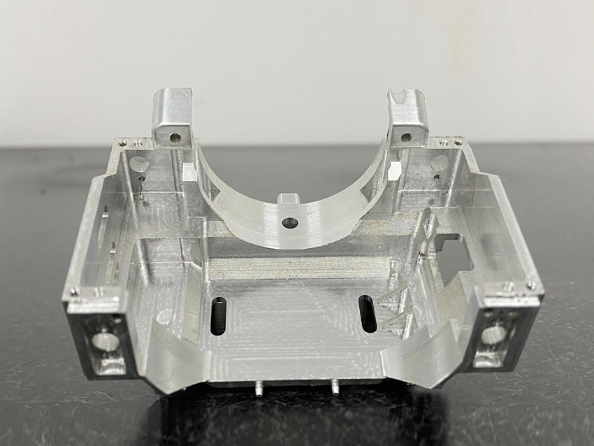
Datums matter because they define how the part is located during machining and how it is evaluated during inspection. In precision machining, the datum system is not only a drawing convention. It directly influences setup order, fixture design, machining sequence, and measurement strategy. If the manufacturing datum does not match the inspection datum, or if both differ from the real assembly reference, a part may pass local measurements and still fail in application.
This problem becomes more serious on custom parts with multiple machined sides, locating holes, sealing faces, or stacked feature relationships. In those cases, the datum structure determines whether the final part will position correctly in the assembly. For high-value parts, datum planning should begin before the first setup and remain consistent through machining and inspection. That is one reason many teams combine datum-sensitive parts with broader CNC Machining planning only after the 2D drawing and GD&T scheme are fully understood.
How GD&T Affects Precision Machining Strategy
GD&T changes machining strategy because it defines how features must relate to one another, not just how large or small they are. A part with position tolerance, perpendicularity, flatness, or profile requirements may need a completely different sequence than a part with standard size tolerances only. In these projects, machining cannot be planned feature by feature in isolation. The route must protect the reference structure that the GD&T scheme depends on.
GD&T Requirement | Manufacturing Impact | Typical Inspection Method |
|---|---|---|
Position tolerance | Requires stable datum setup and consistent feature location strategy | CMM |
Flatness | Requires controlled finishing pass and distortion awareness | Surface plate / CMM |
Parallelism | Requires consistent datum reference across multiple surfaces | CMM |
Perpendicularity | Requires accurate fixture alignment and controlled tool approach | CMM |
Concentricity | Requires controlled turning or boring relative to the true axis reference | CMM / roundness inspection |
Circularity | Requires stable rotational geometry and fine process control | Roundness inspection |
Profile tolerance | Requires controlled toolpath, surface stability, and datum consistency | CMM scanning |
For more complex surfaces or multi-face geometry, these requirements often benefit from multi-axis machining because reducing setup transfer can help protect feature relationships defined by GD&T.
Precision Machining Challenges for Complex Custom Parts
Complex custom parts introduce more risk because several sources of variation can affect the same datum structure. Multi-face machining often requires multiple setups, and each setup adds the possibility of reference transfer error. Thin-wall sections may deform during machining or release stress after stock removal. Deep cavities, narrow slots, and long holes can increase tool deflection and reduce local accuracy. Heat treatment may shift geometry, and internal material stress can affect flatness or orientation after rough machining.
These risks become even more important when the part must later be repeated in small batches or production quantities. A part can sometimes be made once with careful manual adjustment, but a real precision machining supplier must be able to plan a route that keeps the same datum logic and feature relationships stable across repeated orders. That is the difference between machining a complex part and industrializing it correctly.
How to Plan the Machining Process for Datum-Controlled Parts
For datum-controlled parts, machining should begin with drawing review rather than with toolpath generation. The first step is to study the 2D drawing and identify how the design uses primary, secondary, and tertiary datums. From there, the machining sequence should be built so those references are established in a stable order and preserved through later operations. In many projects, this requires dedicated soft jaws, custom fixtures, or a multi-stage setup plan rather than a general-purpose workholding approach.
A typical route may include review of the drawing and GD&T scheme, identification of datums, definition of the machining sequence, fixture planning, rough machining with controlled stock allowance, stress relief or heat treatment if needed, finish machining of critical features, and final inspection of size and GD&T requirements. For development-stage parts, CNC Machining Prototyping can also be valuable when the buyer wants to verify datum logic and assembly function before a repeat production route is fully locked.
Process Step | Purpose |
|---|---|
Review 2D drawing and GD&T | Understand the real functional geometry before machining |
Identify primary, secondary, and tertiary datums | Establish the true machining and inspection reference structure |
Define machining sequence | Protect feature relationships through each operation |
Design fixtures or soft jaws | Stabilize the part and preserve datum logic |
Rough machining with controlled allowance | Remove stock without sacrificing final feature stability |
Stress relief or heat treatment if needed | Manage distortion before final precision cuts |
Finish machining critical features | Hold the final dimensions and GD&T relationships |
Inspect critical dimensions and GD&T | Verify function, not just local size |
Why Inspection Planning Should Start Before Machining
Inspection should not be treated as a final administrative step added after machining is complete. For complex precision parts, the inspection method influences how the part should be machined in the first place. If a customer requires a CMM report, FAI, material certificate, or feature-specific geometry verification, those needs should be confirmed at quoting stage so the manufacturing route can support them. Otherwise, the supplier may machine the part successfully but still lack the proper reference logic or measurement path to verify it correctly.
This is especially important for datum-controlled parts because the inspection datum and manufacturing datum should either match or be intentionally related. If they do not, a part can pass size checks but fail assembly or system-level function. That is why many buyers working on critical custom parts review inspection expectations together with quality control in CNC machining before releasing the order.
What Information Should Buyers Provide for Custom Precision Machining?
A good RFQ for custom precision machining should give the supplier enough information to understand the part’s true engineering intent, not only its shape. That means the RFQ package should include both model data and the feature-specific requirements that define how the part will be made and inspected.
RFQ Information | Why It Is Needed |
|---|---|
3D CAD files: STEP, X_T, IGS | Define geometry and machining access |
2D drawings with tolerances | Define critical dimensions and GD&T logic |
Material specification | Affects machining, fixturing, heat treatment, and inspection |
Surface finish requirements | Clarify functional and cosmetic surface expectations |
Heat treatment requirements | Influence process order and distortion control |
Critical dimensions | Help prioritize the process around function-critical features |
Quantity | Affects fixture planning and repeatability strategy |
Inspection report requirements | Define whether CMM, FAI, or other reporting is required |
Application or assembly environment | Helps confirm which requirements cannot be reduced |
Choosing a Precision Machining Supplier for GD&T Parts
A suitable supplier for GD&T-controlled parts should be able to do more than machine to nominal size. They should understand engineering drawings, plan the route around the datum system, design stable fixturing, support CMM-based inspection, and manage materials or heat treatment in a way that protects final geometry. They should also be able to explain how repeatability will be maintained across low-volume and production orders, not just how the first sample will be made.
For buyers sourcing custom parts with positional, profile, flatness, perpendicularity, and datum-related requirements, Neway can support that process through Precision Machining with engineering review tied to drawing intent and inspection planning. In these projects, the strongest supplier is usually the one that understands why the part is difficult, not just how to cut it.
FAQ
What tolerances can precision machining achieve for custom metal parts?
What information is needed to quote precision machined parts?
How does GD&T affect precision machining cost and inspection?
What inspection reports are recommended for precision machined components?
How do you choose a precision machining supplier for low-volume and production parts?