
English
How does GD&T affect precision machining cost and inspection?
Table of Contents
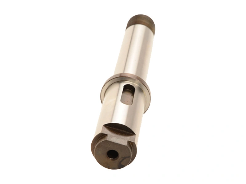
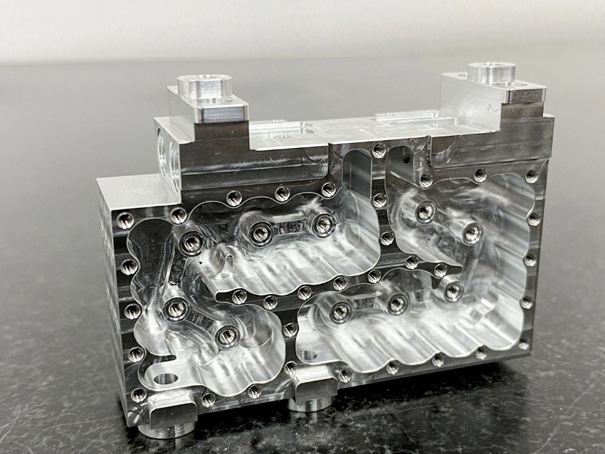
<h2 id="how-does-gd-and-t-affect-precision-machining-cost-and-inspection?">How Does GD&T Affect Precision Machining Cost and Inspection?</h2><p>GD&T changes precision machining cost through the functional relationships it controls, not symbol count. Position, flatness, perpendicularity, axis, and profile controls can require a defined datum frame, extra setups, controlled clamping, finish passes, and reachable measurement. Cost depends on material condition, geometry, tolerance zone, access, production stage, and required evidence.</p><p>GD&T is a manufacturing and acceptance contract, not only a drawing language. A feature control frame defines how a surface, hole, or axis relates to datums and how it must be verified. If a drawing invokes ASME Y14.5, identify its applicable revision; the standard does not guarantee a finished-part tolerance. GD&T therefore affects sequence, datum selection, fixture design, inspection, and acceptance for <a target="_blank" href="https://www.newaymachining.com/services/precision-machining">precision machining services</a>.</p><div data-type="row" class="row"><div class="col-12 col-md-6" data-type="col"><p><a href="https://www.newaymachining.com/services/precision-machining"><img src="https://www.newaymachining.com/storage/attachments/2026/05/11/gd-and-t-precision-machining-gd-and-t-machining-cost.webp" width="800" height="600" loading="lazy"></a></p></div><div class="col-12 col-md-6" data-type="col"><p><a href="https://www.newaymachining.com/services/precision-machining"><img src="https://www.newaymachining.com/storage/attachments/2026/05/11/how-does-gd-and-t-affect-precision-machining-cost-and-inspection.webp" width="800" height="600" loading="lazy"></a></p></div></div><h3 id="1.-how-gd-and-t-requirements-affect-machining-cost">1. How GD&T Requirements Affect Machining Cost</h3><div class="i-typography-table-responsive"><table><tbody><tr><th colspan="1" rowspan="1"><p>GD&T Requirement</p></th><th colspan="1" rowspan="1"><p>Machining Impact</p></th><th colspan="1" rowspan="1"><p>Cost / Inspection Impact</p></th></tr><tr><td colspan="1" rowspan="1"><p>Position tolerance</p></td><td colspan="1" rowspan="1"><p>Needs a stable datum setup, hole-location strategy, and control of pattern orientation</p></td><td colspan="1" rowspan="1"><p>Quote the required datum simulator, probing, and report scope rather than assuming every hole needs a full CMM study</p></td></tr><tr><td colspan="1" rowspan="1"><p>Flatness</p></td><td colspan="1" rowspan="1"><p>Requires a finishing sequence and clamping method that do not distort a broad functional face</p></td><td colspan="1" rowspan="1"><p>May add stress-relief, re-fixturing, surface-plate checks, or a defined sampling plan</p></td></tr><tr><td colspan="1" rowspan="1"><p>Parallelism</p></td><td colspan="1" rowspan="1"><p>Requires fixture alignment and machining from the specified datum surfaces, not only a convenient outside edge</p></td><td colspan="1" rowspan="1"><p>Needs datum-based measurement and an agreed reference frame in the inspection report</p></td></tr><tr><td colspan="1" rowspan="1"><p>Perpendicularity</p></td><td colspan="1" rowspan="1"><p>Requires controlled setup across related faces or axes and stable tool access at the finishing step</p></td><td colspan="1" rowspan="1"><p>Inspection cost depends on feature access, datum simulation, and whether a report or only a recorded result is required</p></td></tr><tr><td colspan="1" rowspan="1"><p>Axis or concentricity relation</p></td><td colspan="1" rowspan="1"><p>May require turning, boring, grinding, or one controlled axis through several operations</p></td><td colspan="1" rowspan="1"><p>Choose bore, shaft, runout, or CMM checks according to the drawing characteristic and assembly function</p></td></tr><tr><td colspan="1" rowspan="1"><p>Profile tolerance</p></td><td colspan="1" rowspan="1"><p>Requires an accurate toolpath, datum control, cutter condition, and consistent material-removal sequence</p></td><td colspan="1" rowspan="1"><p>May require CMM scanning or optical inspection when the profile is functional and the surface is difficult to reach</p></td></tr></tbody></table></div><h3 id="2.-datums-control-both-machining-and-inspection">2. Datums Control Both Machining and Inspection</h3><p>Datums control cost because they define the part origin for the fixture, machine coordinates, and inspection setup. Primary, secondary, and tertiary features constrain degrees of freedom; a datum simulator represents the mating condition. Identify whether each datum is a plane, bore, slot, or functional interface before choosing stock, locating points, and setup order.</p><p>If machining and inspection datums differ, a part can measure correctly in one setup yet fail during assembly. A thin mounting plate with locating holes and a sealing face may move after unclamping or heat treatment. The quote should state the controlled state, datum sequence, re-location method, and whether final checking occurs after stress relief. Buyers should identify functional relationships and surfaces that may use general tolerances.</p><h3 id="3.-complex-gd-and-t-parts-may-need-multi-axis-machining">3. Complex GD&T Parts May Need Multi-Axis Machining</h3><p>Several datum-related faces, angled features, compound surfaces, or multi-side hole patterns can make repeated three-axis setups the main process risk. <a target="_blank" href="https://www.newaymachining.com/services/multi-axis-machining">multi-axis machining</a> can reduce re-location error when the tool, part, and datum frame are verified in one controlled sequence, but it is not automatically cheaper or more accurate for every part.</p><p>For milled planes, hole groups, pockets, and profiles, <a target="_blank" href="https://www.newaymachining.com/services/cnc-milling">CNC milling services</a> should be selected after reviewing access, tool length, workholding, finish, and inspection evidence. The request for quotation (RFQ) should identify shared datum features and separate checks so a process label does not replace a functional tolerance decision.</p><h3 id="4.-cmm-inspection-is-often-required-for-gd-and-t-parts">4. CMM Inspection Is Often Required for GD&T Parts</h3><p>For GD&T-controlled parts, caliper readings cannot establish many relationships between features. Position, profile, perpendicularity, parallelism, and datum-based axes may require a coordinate measuring machine (CMM), height gauge, bore gauge, surface plate, optical system, or functional gauge. The method depends on characteristic type, tolerance zone, datum access, surface condition, and permitted measurement uncertainty.</p><p>Agree the inspection method before quotation. A CMM program, datum simulator, full-dimensional report, first article inspection (FAI), and repeat sampling each add effort. A report can show measured values without proving that the datum setup matches assembly, so the RFQ should specify reference frame, inspection state, records, and treatment of out-of-tolerance results before release.</p><h3 id="5.-turning-features-require-axis-and-concentricity-control">5. Turning Features Require Axis and Concentricity Control</h3><p>For shafts, pins, sleeves, bushings, and round components, GD&T may govern an axis, circular runout, cylindricity, perpendicular shoulder, or bearing surface. In these cases, <a target="_blank" href="https://www.newaymachining.com/services/cnc-turning">CNC turning services</a> can control related features in one setup, while boring or grinding may follow heat treatment or serve a different functional surface.</p><p>For combined milled and turned features, define which datum is established first and how the part is re-located. A diameter inspected before later milling may not prove the final axis relationship. Buyers should state the assembly datum, material and heat-treatment state, runout or location characteristic, and final inspection sequence so the quote includes the verification work.</p><h3 id="6.-how-buyers-can-reduce-unnecessary-gd-and-t-cost">6. How Buyers Can Reduce Unnecessary GD&T Cost</h3><p>Buyers can reduce unnecessary cost by applying strict GD&T to features controlling fit, sealing, location, motion, or load transfer. Bearing seats, sealing faces, locating holes, precision bores, mating surfaces, and motion-control features may need relationship controls. Clearance areas, non-functional profiles, and cosmetic surfaces can often use a stated general tolerance when the drawing explains the functional boundary.</p><div class="i-typography-table-responsive"><table><tbody><tr><th colspan="1" rowspan="1"><p>Cost-Control Action</p></th><th colspan="1" rowspan="1"><p>Engineering Benefit</p></th></tr><tr><td colspan="1" rowspan="1"><p>Define GD&T only on function-critical features</p></td><td colspan="1" rowspan="1"><p>Reduces machining and inspection burden while keeping fit and sealing decisions explicit</p></td></tr><tr><td colspan="1" rowspan="1"><p>Avoid full-drawing tight tolerance</p></td><td colspan="1" rowspan="1"><p>Prevents a broad tolerance demand from forcing unnecessary finishing, setups, and reports</p></td></tr><tr><td colspan="1" rowspan="1"><p>Clearly define datum A, B, and C</p></td><td colspan="1" rowspan="1"><p>Improves fixture planning, coordinate alignment, and inspection consistency</p></td></tr><tr><td colspan="1" rowspan="1"><p>Specify which features need CMM or FAI records</p></td><td colspan="1" rowspan="1"><p>Controls documentation effort and separates critical evidence from routine in-process checks</p></td></tr><tr><td colspan="1" rowspan="1"><p>Use general tolerance for non-critical dimensions</p></td><td colspan="1" rowspan="1"><p>Improves manufacturability when the drawing states the material, process, and functional limits</p></td></tr></tbody></table></div><h3 id="7.-practical-engineering-recommendation">7. Practical Engineering Recommendation</h3><p>Review GD&T before requesting a firm quote because it determines datum scheme, setup count, process sequence, inspection access, and required records. Provide the controlled 2D drawing, three-dimensional computer-aided design (CAD) model, material grade and condition, heat-treatment or coating state, datum scheme, critical features, quantity by stage, and report requirements. Ask the supplier to list assumptions and identify features that cannot be verified in the stated final condition.</p><p>For a thin mounting plate with locating holes and a sealing face, decide whether position and flatness are checked after stress relief and unclamping, which datum simulator represents assembly, and what evidence releases the lot. A quotation is comparable only when drawing interpretation, machining route, inspection method, deviation approval, and change control are explicit.</p>
<h2 id="how-does-gd-and-t-affect-precision-machining-cost-and-inspection?">How Does GD&T Affect Precision Machining Cost and Inspection?</h2><p>GD&T changes precision machining cost through the functional relationships it controls, not symbol count. Position, flatness, perpendicularity, axis, and profile controls can require a defined datum frame, extra setups, controlled clamping, finish passes, and reachable measurement. Cost depends on material condition, geometry, tolerance zone, access, production stage, and required evidence.</p><p>GD&T is a manufacturing and acceptance contract, not only a drawing language. A feature control frame defines how a surface, hole, or axis relates to datums and how it must be verified. If a drawing invokes ASME Y14.5, identify its applicable revision; the standard does not guarantee a finished-part tolerance. GD&T therefore affects sequence, datum selection, fixture design, inspection, and acceptance for <a target="_blank" href="https://www.newaymachining.com/services/precision-machining">precision machining services</a>.</p><div data-type="row" class="row"><div class="col-12 col-md-6" data-type="col"><p><a href="https://www.newaymachining.com/services/precision-machining"><img src="https://www.newaymachining.com/storage/attachments/2026/05/11/gd-and-t-precision-machining-gd-and-t-machining-cost.webp" width="800" height="600" loading="lazy"></a></p></div><div class="col-12 col-md-6" data-type="col"><p><a href="https://www.newaymachining.com/services/precision-machining"><img src="https://www.newaymachining.com/storage/attachments/2026/05/11/how-does-gd-and-t-affect-precision-machining-cost-and-inspection.webp" width="800" height="600" loading="lazy"></a></p></div></div><h3 id="1.-how-gd-and-t-requirements-affect-machining-cost">1. How GD&T Requirements Affect Machining Cost</h3><div class="i-typography-table-responsive"><table><tbody><tr><th colspan="1" rowspan="1"><p>GD&T Requirement</p></th><th colspan="1" rowspan="1"><p>Machining Impact</p></th><th colspan="1" rowspan="1"><p>Cost / Inspection Impact</p></th></tr><tr><td colspan="1" rowspan="1"><p>Position tolerance</p></td><td colspan="1" rowspan="1"><p>Needs a stable datum setup, hole-location strategy, and control of pattern orientation</p></td><td colspan="1" rowspan="1"><p>Quote the required datum simulator, probing, and report scope rather than assuming every hole needs a full CMM study</p></td></tr><tr><td colspan="1" rowspan="1"><p>Flatness</p></td><td colspan="1" rowspan="1"><p>Requires a finishing sequence and clamping method that do not distort a broad functional face</p></td><td colspan="1" rowspan="1"><p>May add stress-relief, re-fixturing, surface-plate checks, or a defined sampling plan</p></td></tr><tr><td colspan="1" rowspan="1"><p>Parallelism</p></td><td colspan="1" rowspan="1"><p>Requires fixture alignment and machining from the specified datum surfaces, not only a convenient outside edge</p></td><td colspan="1" rowspan="1"><p>Needs datum-based measurement and an agreed reference frame in the inspection report</p></td></tr><tr><td colspan="1" rowspan="1"><p>Perpendicularity</p></td><td colspan="1" rowspan="1"><p>Requires controlled setup across related faces or axes and stable tool access at the finishing step</p></td><td colspan="1" rowspan="1"><p>Inspection cost depends on feature access, datum simulation, and whether a report or only a recorded result is required</p></td></tr><tr><td colspan="1" rowspan="1"><p>Axis or concentricity relation</p></td><td colspan="1" rowspan="1"><p>May require turning, boring, grinding, or one controlled axis through several operations</p></td><td colspan="1" rowspan="1"><p>Choose bore, shaft, runout, or CMM checks according to the drawing characteristic and assembly function</p></td></tr><tr><td colspan="1" rowspan="1"><p>Profile tolerance</p></td><td colspan="1" rowspan="1"><p>Requires an accurate toolpath, datum control, cutter condition, and consistent material-removal sequence</p></td><td colspan="1" rowspan="1"><p>May require CMM scanning or optical inspection when the profile is functional and the surface is difficult to reach</p></td></tr></tbody></table></div><h3 id="2.-datums-control-both-machining-and-inspection">2. Datums Control Both Machining and Inspection</h3><p>Datums control cost because they define the part origin for the fixture, machine coordinates, and inspection setup. Primary, secondary, and tertiary features constrain degrees of freedom; a datum simulator represents the mating condition. Identify whether each datum is a plane, bore, slot, or functional interface before choosing stock, locating points, and setup order.</p><p>If machining and inspection datums differ, a part can measure correctly in one setup yet fail during assembly. A thin mounting plate with locating holes and a sealing face may move after unclamping or heat treatment. The quote should state the controlled state, datum sequence, re-location method, and whether final checking occurs after stress relief. Buyers should identify functional relationships and surfaces that may use general tolerances.</p><h3 id="3.-complex-gd-and-t-parts-may-need-multi-axis-machining">3. Complex GD&T Parts May Need Multi-Axis Machining</h3><p>Several datum-related faces, angled features, compound surfaces, or multi-side hole patterns can make repeated three-axis setups the main process risk. <a target="_blank" href="https://www.newaymachining.com/services/multi-axis-machining">multi-axis machining</a> can reduce re-location error when the tool, part, and datum frame are verified in one controlled sequence, but it is not automatically cheaper or more accurate for every part.</p><p>For milled planes, hole groups, pockets, and profiles, <a target="_blank" href="https://www.newaymachining.com/services/cnc-milling">CNC milling services</a> should be selected after reviewing access, tool length, workholding, finish, and inspection evidence. The request for quotation (RFQ) should identify shared datum features and separate checks so a process label does not replace a functional tolerance decision.</p><h3 id="4.-cmm-inspection-is-often-required-for-gd-and-t-parts">4. CMM Inspection Is Often Required for GD&T Parts</h3><p>For GD&T-controlled parts, caliper readings cannot establish many relationships between features. Position, profile, perpendicularity, parallelism, and datum-based axes may require a coordinate measuring machine (CMM), height gauge, bore gauge, surface plate, optical system, or functional gauge. The method depends on characteristic type, tolerance zone, datum access, surface condition, and permitted measurement uncertainty.</p><p>Agree the inspection method before quotation. A CMM program, datum simulator, full-dimensional report, first article inspection (FAI), and repeat sampling each add effort. A report can show measured values without proving that the datum setup matches assembly, so the RFQ should specify reference frame, inspection state, records, and treatment of out-of-tolerance results before release.</p><h3 id="5.-turning-features-require-axis-and-concentricity-control">5. Turning Features Require Axis and Concentricity Control</h3><p>For shafts, pins, sleeves, bushings, and round components, GD&T may govern an axis, circular runout, cylindricity, perpendicular shoulder, or bearing surface. In these cases, <a target="_blank" href="https://www.newaymachining.com/services/cnc-turning">CNC turning services</a> can control related features in one setup, while boring or grinding may follow heat treatment or serve a different functional surface.</p><p>For combined milled and turned features, define which datum is established first and how the part is re-located. A diameter inspected before later milling may not prove the final axis relationship. Buyers should state the assembly datum, material and heat-treatment state, runout or location characteristic, and final inspection sequence so the quote includes the verification work.</p><h3 id="6.-how-buyers-can-reduce-unnecessary-gd-and-t-cost">6. How Buyers Can Reduce Unnecessary GD&T Cost</h3><p>Buyers can reduce unnecessary cost by applying strict GD&T to features controlling fit, sealing, location, motion, or load transfer. Bearing seats, sealing faces, locating holes, precision bores, mating surfaces, and motion-control features may need relationship controls. Clearance areas, non-functional profiles, and cosmetic surfaces can often use a stated general tolerance when the drawing explains the functional boundary.</p><div class="i-typography-table-responsive"><table><tbody><tr><th colspan="1" rowspan="1"><p>Cost-Control Action</p></th><th colspan="1" rowspan="1"><p>Engineering Benefit</p></th></tr><tr><td colspan="1" rowspan="1"><p>Define GD&T only on function-critical features</p></td><td colspan="1" rowspan="1"><p>Reduces machining and inspection burden while keeping fit and sealing decisions explicit</p></td></tr><tr><td colspan="1" rowspan="1"><p>Avoid full-drawing tight tolerance</p></td><td colspan="1" rowspan="1"><p>Prevents a broad tolerance demand from forcing unnecessary finishing, setups, and reports</p></td></tr><tr><td colspan="1" rowspan="1"><p>Clearly define datum A, B, and C</p></td><td colspan="1" rowspan="1"><p>Improves fixture planning, coordinate alignment, and inspection consistency</p></td></tr><tr><td colspan="1" rowspan="1"><p>Specify which features need CMM or FAI records</p></td><td colspan="1" rowspan="1"><p>Controls documentation effort and separates critical evidence from routine in-process checks</p></td></tr><tr><td colspan="1" rowspan="1"><p>Use general tolerance for non-critical dimensions</p></td><td colspan="1" rowspan="1"><p>Improves manufacturability when the drawing states the material, process, and functional limits</p></td></tr></tbody></table></div><h3 id="7.-practical-engineering-recommendation">7. Practical Engineering Recommendation</h3><p>Review GD&T before requesting a firm quote because it determines datum scheme, setup count, process sequence, inspection access, and required records. Provide the controlled 2D drawing, three-dimensional computer-aided design (CAD) model, material grade and condition, heat-treatment or coating state, datum scheme, critical features, quantity by stage, and report requirements. Ask the supplier to list assumptions and identify features that cannot be verified in the stated final condition.</p><p>For a thin mounting plate with locating holes and a sealing face, decide whether position and flatness are checked after stress relief and unclamping, which datum simulator represents assembly, and what evidence releases the lot. A quotation is comparable only when drawing interpretation, machining route, inspection method, deviation approval, and change control are explicit.</p>
Related Blogs

Subscribe for expert design and manufacturing tips delivered to your inbox.
Share this Post:

Neway Precision Works Ltd.
No.3 Lefushan Industry West Road
Fenggang, Dongguan, China
ZIP 523000
Solutions
Copyright © 2026 Machining Precision Works Ltd.All Rights Reserved.