
English
What tolerances can precision machining achieve for custom metal parts?
Table of Contents
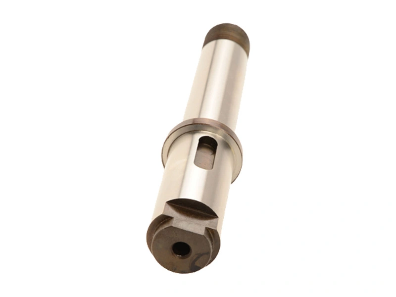
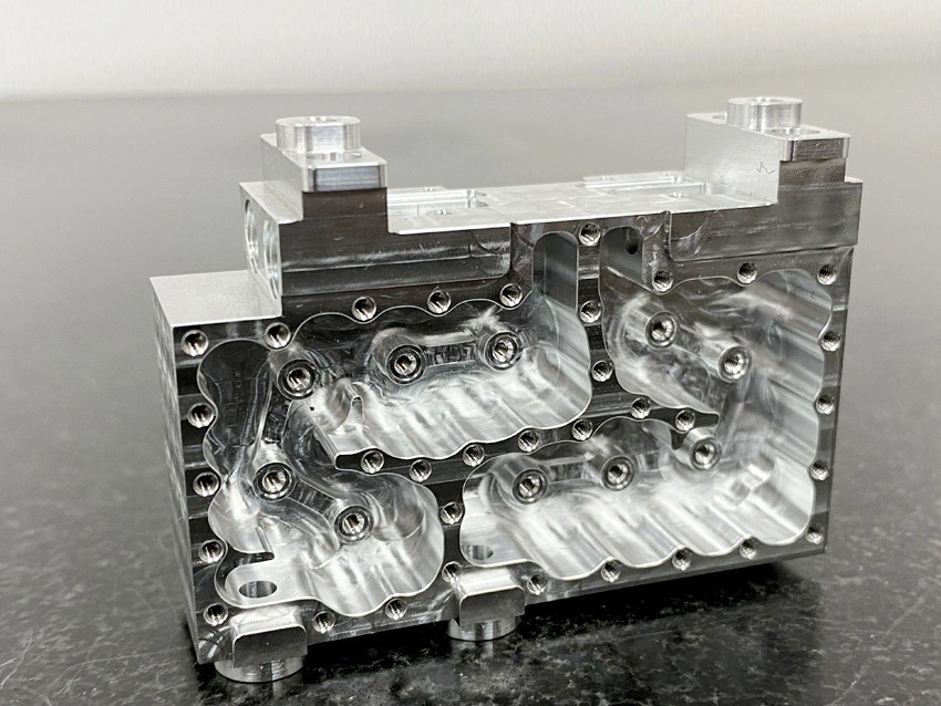
<h2 id="what-tolerances-can-precision-machining-achieve-for-custom-metal-parts?">What Tolerances Can Precision Machining Achieve for Custom Metal Parts?</h2><p><a target="_blank" href="https://www.newaymachining.com/services/precision-machining">Precision machining services</a> can achieve a required tolerance only when the tolerance is assigned to a defined feature, material state, datum scheme, process route, and measurement method. There is no defensible single tolerance number for every custom metal part. A short bore, a long thin-wall housing, a heat-treated tool-steel insert, and a sealing face can require different controls even when their nominal dimensions are similar. Buyers should identify the functional feature, allowable variation, mating condition, and final inspection state before asking a supplier to assess feasibility.</p><p>General tolerances can be useful for noncritical dimensions when the drawing invokes an applicable standard such as ISO 2768 and states its class and scope. Critical dimensions need their own size and geometric controls on the controlled drawing. The drawing must also show the datums that establish the functional relationship. Machine positioning, repeatability, or coordinate-measuring-machine resolution does not by itself prove a finished-part tolerance. Clamping movement, tool wear, thermal condition, heat treatment, burr removal, surface finishing, and measurement access can change the result between setup and final acceptance.</p><div data-type="row" class="row"><div class="col-12 col-md-6" data-type="col"><p><a href="https://www.newaymachining.com/services/precision-machining"><img src="https://www.newaymachining.com/storage/attachments/2026/05/11/precision-machining-tolerances-tight-tolerance-machining.webp" width="800" height="600" loading="lazy"></a></p></div><div class="col-12 col-md-6" data-type="col"><p><a href="https://www.newaymachining.com/services/precision-machining"><img src="https://www.newaymachining.com/storage/attachments/2026/05/11/what-tolerances-can-precision-machining-achieve-for-custom-metal-parts.webp" width="800" height="600" loading="lazy"></a></p></div></div><h3 id="1.-typical-factors-that-affect-precision-machining-tolerances">1. Typical Factors That Affect Precision Machining Tolerances</h3><div class="i-typography-table-responsive"><table><tbody><tr><th colspan="1" rowspan="1"><p>Factor</p></th><th colspan="1" rowspan="1"><p>Impact on Tolerance Control</p></th></tr><tr><td colspan="1" rowspan="1"><p>Material</p></td><td colspan="1" rowspan="1"><p>Alloy, product form, residual stress, and heat-treatment state affect cutting response and movement. Confirm the specified material condition before fixing the final process route.</p></td></tr><tr><td colspan="1" rowspan="1"><p>Part size</p></td><td colspan="1" rowspan="1"><p>Long spans and large sections are more sensitive to thermal change, fixture transfer, and measurement support. Define the measurement environment and datum support for the critical feature.</p></td></tr><tr><td colspan="1" rowspan="1"><p>Feature type</p></td><td colspan="1" rowspan="1"><p>Bores, bearing seats, sealing faces, and datum surfaces need feature-specific size, form, location, and surface requirements rather than an unqualified part-wide claim.</p></td></tr><tr><td colspan="1" rowspan="1"><p>Wall thickness</p></td><td colspan="1" rowspan="1"><p>Thin walls can move during clamping, roughing, finishing, or release. The process should check the part after unclamping when final geometry depends on free-state stability.</p></td></tr><tr><td colspan="1" rowspan="1"><p>Heat treatment</p></td><td colspan="1" rowspan="1"><p>Heat treatment can change size, form, and datum relationships. State whether final machining and inspection occur before or after the specified thermal cycle.</p></td></tr><tr><td colspan="1" rowspan="1"><p>Inspection method</p></td><td colspan="1" rowspan="1"><p>CMM, bore gauges, height gauges, roughness testers, and custom gauges answer different questions. Select a method with access and uncertainty appropriate to the acceptance feature.</p></td></tr></tbody></table></div><h3 id="2.-which-features-should-have-critical-tolerances?">2. Which Features Should Have Critical Tolerances?</h3><p>Critical tolerances belong on features that directly control fit, sealing, motion, alignment, load transfer, or an assembly datum. Bearing seats, precision bores, locating holes, shaft journals, sealing faces, mating planes, and sliding interfaces are common examples. The functional requirement should determine whether the drawing needs a size limit, a geometric tolerance, a surface requirement, or a combination. A bore diameter alone does not define the relationship of that bore to a mounting face, and a flatness callout alone does not define how the face locates the assembly.</p><p>Applying tight tolerances to every dimension is not a conservative substitute for functional analysis. It can add special setups, finishing operations, inspection effort, and rejection risk while obscuring the few features that truly govern performance. A practical drawing marks the critical interfaces, establishes datums from stable functional surfaces, and allows general tolerances elsewhere. For example, a non-supplier-specific housing may need a controlled bearing bore and a sealing face after heat treatment, while its external cosmetic profile can remain less restrictive. The buyer should confirm the mating component, operating load, sealing medium, and assembly method before finalizing that allocation.</p><h3 id="3.-process-selection-affects-tolerance-capability">3. Process Selection Affects Tolerance Capability</h3><p>Process selection affects the tolerance result because each route creates and preserves datums differently. <a target="_blank" href="https://www.newaymachining.com/services/cnc-machining">CNC machining services</a> can produce many controlled features when tool access, fixture rigidity, stock condition, and inspection access are suitable. A part with several critical faces or angled features may use <a target="_blank" href="https://www.newaymachining.com/services/multi-axis-machining">multi-axis machining</a> to reduce datum transfer between setups, but reduced repositioning does not remove the need to verify the final datum relationship.</p><p>Roughing, stress relief or heat treatment, semi-finishing, final finishing, deburring, coating, and inspection must be placed in the route according to the controlled feature. A supplier should not quote a final tolerance before knowing whether later grinding, polishing, plating, heat treatment, or assembly changes the inspected state. For prototype development, <a target="_blank" href="https://www.newaymachining.com/services/cnc-machining-prototyping">CNC machining prototyping</a> can test the tolerance strategy, fixture access, and measurement method before a repeated production route is released. The useful output is evidence about a defined feature and condition, not a blanket capability claim for unrelated parts.</p><h3 id="4.-2d-drawings-are-required-for-accurate-tolerance-review">4. 2D Drawings Are Required for Accurate Tolerance Review</h3><p>A three-dimensional CAD model defines nominal shape, but it does not necessarily define size limits, datum precedence, geometric tolerance zones, surface texture, material condition, inspection state, or acceptance rules. A controlled two-dimensional drawing is therefore required for a meaningful tolerance review. The drawing should identify the revision, units, critical dimensions, datums, geometric requirements, material grade, heat-treatment condition, and surfaces whose finish affects function.</p><p>GD&T must be interpreted with the referenced datum structure and the intended functional relationship. The supplier and buyer should resolve unclear callouts before machining starts, especially when a bore, face, or pattern is measured after an operation that can move the part. Inspection reports should state the measurement method and datum setup used for the result. A dimensional report from a different condition can be accurate as a record yet fail to prove the required final condition.</p><h3 id="5.-what-buyers-should-provide-for-tolerance-evaluation">5. What Buyers Should Provide for Tolerance Evaluation</h3><div class="i-typography-table-responsive"><table><tbody><tr><th colspan="1" rowspan="1"><p>Required Information</p></th><th colspan="1" rowspan="1"><p>Why It Is Needed</p></th></tr><tr><td colspan="1" rowspan="1"><p>2D drawing with tolerances</p></td><td colspan="1" rowspan="1"><p>Defines critical size and GD&T requirements, datum precedence, revision, and the final state used for acceptance.</p></td></tr><tr><td colspan="1" rowspan="1"><p>3D CAD file</p></td><td colspan="1" rowspan="1"><p>Shows feature access, wall transitions, fixture clearance, and the route constraints that the drawing alone may not reveal.</p></td></tr><tr><td colspan="1" rowspan="1"><p>Critical dimensions</p></td><td colspan="1" rowspan="1"><p>Identifies the features tied to fit, sealing, motion, or location so process and inspection effort can be focused where it matters.</p></td></tr><tr><td colspan="1" rowspan="1"><p>Material grade</p></td><td colspan="1" rowspan="1"><p>Material grade, product form, and supplied condition affect machining response, stress release, final finishing, and the validity of any prior measurement.</p></td></tr><tr><td colspan="1" rowspan="1"><p>Surface finish</p></td><td colspan="1" rowspan="1"><p>Surface texture can affect sealing, friction, wear, appearance, coating allowance, and the selected inspection method; define the functional surface explicitly.</p></td></tr><tr><td colspan="1" rowspan="1"><p>Heat treatment</p></td><td colspan="1" rowspan="1"><p>Heat-treatment specification and sequence show whether distortion, scale removal, hardness, or final finishing must be considered before acceptance.</p></td></tr><tr><td colspan="1" rowspan="1"><p>Inspection report requirements</p></td><td colspan="1" rowspan="1"><p>Specify feature, datum, method, sampling, record format, and acceptance condition rather than requesting a generic report with no functional traceability.</p></td></tr><tr><td colspan="1" rowspan="1"><p>Quantity</p></td><td colspan="1" rowspan="1"><p>Prototype, low-volume, and repeated production quantities can require different fixture validation, first-article evidence, and change-control decisions.</p></td></tr></tbody></table></div><h3 id="6.-practical-engineering-recommendation">6. Practical Engineering Recommendation</h3><p>Evaluate precision-machining tolerance feature by feature and accept it only in the material, thermal, surface, and datum condition stated by the drawing. A useful engineering review connects the functional interface to a controllable machining sequence and an accessible measurement. If a tolerance cannot be inspected from the specified datums after the final operation, the risk is not solved by tightening the number. The drawing, process plan, and inspection plan need a consistent definition of the final part state.</p><p>For an RFQ, provide the controlled 3D model, 2D drawing, mating-feature purpose, material and heat-treatment condition, critical datums, GD&T, surface requirements, quantity, and required inspection evidence. Ask the supplier to identify process assumptions, finishing steps, measurement access, and any feature that needs a change before release. Approve changes to datum selection, material condition, heat-treatment sequence, finishing allowance, inspection method, or sampling plan before they affect production. This gives buyers a reviewable basis for deciding whether a proposed route can protect the required custom-part tolerances.</p>
<h2 id="what-tolerances-can-precision-machining-achieve-for-custom-metal-parts?">What Tolerances Can Precision Machining Achieve for Custom Metal Parts?</h2><p><a target="_blank" href="https://www.newaymachining.com/services/precision-machining">Precision machining services</a> can achieve a required tolerance only when the tolerance is assigned to a defined feature, material state, datum scheme, process route, and measurement method. There is no defensible single tolerance number for every custom metal part. A short bore, a long thin-wall housing, a heat-treated tool-steel insert, and a sealing face can require different controls even when their nominal dimensions are similar. Buyers should identify the functional feature, allowable variation, mating condition, and final inspection state before asking a supplier to assess feasibility.</p><p>General tolerances can be useful for noncritical dimensions when the drawing invokes an applicable standard such as ISO 2768 and states its class and scope. Critical dimensions need their own size and geometric controls on the controlled drawing. The drawing must also show the datums that establish the functional relationship. Machine positioning, repeatability, or coordinate-measuring-machine resolution does not by itself prove a finished-part tolerance. Clamping movement, tool wear, thermal condition, heat treatment, burr removal, surface finishing, and measurement access can change the result between setup and final acceptance.</p><div data-type="row" class="row"><div class="col-12 col-md-6" data-type="col"><p><a href="https://www.newaymachining.com/services/precision-machining"><img src="https://www.newaymachining.com/storage/attachments/2026/05/11/precision-machining-tolerances-tight-tolerance-machining.webp" width="800" height="600" loading="lazy"></a></p></div><div class="col-12 col-md-6" data-type="col"><p><a href="https://www.newaymachining.com/services/precision-machining"><img src="https://www.newaymachining.com/storage/attachments/2026/05/11/what-tolerances-can-precision-machining-achieve-for-custom-metal-parts.webp" width="800" height="600" loading="lazy"></a></p></div></div><h3 id="1.-typical-factors-that-affect-precision-machining-tolerances">1. Typical Factors That Affect Precision Machining Tolerances</h3><div class="i-typography-table-responsive"><table><tbody><tr><th colspan="1" rowspan="1"><p>Factor</p></th><th colspan="1" rowspan="1"><p>Impact on Tolerance Control</p></th></tr><tr><td colspan="1" rowspan="1"><p>Material</p></td><td colspan="1" rowspan="1"><p>Alloy, product form, residual stress, and heat-treatment state affect cutting response and movement. Confirm the specified material condition before fixing the final process route.</p></td></tr><tr><td colspan="1" rowspan="1"><p>Part size</p></td><td colspan="1" rowspan="1"><p>Long spans and large sections are more sensitive to thermal change, fixture transfer, and measurement support. Define the measurement environment and datum support for the critical feature.</p></td></tr><tr><td colspan="1" rowspan="1"><p>Feature type</p></td><td colspan="1" rowspan="1"><p>Bores, bearing seats, sealing faces, and datum surfaces need feature-specific size, form, location, and surface requirements rather than an unqualified part-wide claim.</p></td></tr><tr><td colspan="1" rowspan="1"><p>Wall thickness</p></td><td colspan="1" rowspan="1"><p>Thin walls can move during clamping, roughing, finishing, or release. The process should check the part after unclamping when final geometry depends on free-state stability.</p></td></tr><tr><td colspan="1" rowspan="1"><p>Heat treatment</p></td><td colspan="1" rowspan="1"><p>Heat treatment can change size, form, and datum relationships. State whether final machining and inspection occur before or after the specified thermal cycle.</p></td></tr><tr><td colspan="1" rowspan="1"><p>Inspection method</p></td><td colspan="1" rowspan="1"><p>CMM, bore gauges, height gauges, roughness testers, and custom gauges answer different questions. Select a method with access and uncertainty appropriate to the acceptance feature.</p></td></tr></tbody></table></div><h3 id="2.-which-features-should-have-critical-tolerances?">2. Which Features Should Have Critical Tolerances?</h3><p>Critical tolerances belong on features that directly control fit, sealing, motion, alignment, load transfer, or an assembly datum. Bearing seats, precision bores, locating holes, shaft journals, sealing faces, mating planes, and sliding interfaces are common examples. The functional requirement should determine whether the drawing needs a size limit, a geometric tolerance, a surface requirement, or a combination. A bore diameter alone does not define the relationship of that bore to a mounting face, and a flatness callout alone does not define how the face locates the assembly.</p><p>Applying tight tolerances to every dimension is not a conservative substitute for functional analysis. It can add special setups, finishing operations, inspection effort, and rejection risk while obscuring the few features that truly govern performance. A practical drawing marks the critical interfaces, establishes datums from stable functional surfaces, and allows general tolerances elsewhere. For example, a non-supplier-specific housing may need a controlled bearing bore and a sealing face after heat treatment, while its external cosmetic profile can remain less restrictive. The buyer should confirm the mating component, operating load, sealing medium, and assembly method before finalizing that allocation.</p><h3 id="3.-process-selection-affects-tolerance-capability">3. Process Selection Affects Tolerance Capability</h3><p>Process selection affects the tolerance result because each route creates and preserves datums differently. <a target="_blank" href="https://www.newaymachining.com/services/cnc-machining">CNC machining services</a> can produce many controlled features when tool access, fixture rigidity, stock condition, and inspection access are suitable. A part with several critical faces or angled features may use <a target="_blank" href="https://www.newaymachining.com/services/multi-axis-machining">multi-axis machining</a> to reduce datum transfer between setups, but reduced repositioning does not remove the need to verify the final datum relationship.</p><p>Roughing, stress relief or heat treatment, semi-finishing, final finishing, deburring, coating, and inspection must be placed in the route according to the controlled feature. A supplier should not quote a final tolerance before knowing whether later grinding, polishing, plating, heat treatment, or assembly changes the inspected state. For prototype development, <a target="_blank" href="https://www.newaymachining.com/services/cnc-machining-prototyping">CNC machining prototyping</a> can test the tolerance strategy, fixture access, and measurement method before a repeated production route is released. The useful output is evidence about a defined feature and condition, not a blanket capability claim for unrelated parts.</p><h3 id="4.-2d-drawings-are-required-for-accurate-tolerance-review">4. 2D Drawings Are Required for Accurate Tolerance Review</h3><p>A three-dimensional CAD model defines nominal shape, but it does not necessarily define size limits, datum precedence, geometric tolerance zones, surface texture, material condition, inspection state, or acceptance rules. A controlled two-dimensional drawing is therefore required for a meaningful tolerance review. The drawing should identify the revision, units, critical dimensions, datums, geometric requirements, material grade, heat-treatment condition, and surfaces whose finish affects function.</p><p>GD&T must be interpreted with the referenced datum structure and the intended functional relationship. The supplier and buyer should resolve unclear callouts before machining starts, especially when a bore, face, or pattern is measured after an operation that can move the part. Inspection reports should state the measurement method and datum setup used for the result. A dimensional report from a different condition can be accurate as a record yet fail to prove the required final condition.</p><h3 id="5.-what-buyers-should-provide-for-tolerance-evaluation">5. What Buyers Should Provide for Tolerance Evaluation</h3><div class="i-typography-table-responsive"><table><tbody><tr><th colspan="1" rowspan="1"><p>Required Information</p></th><th colspan="1" rowspan="1"><p>Why It Is Needed</p></th></tr><tr><td colspan="1" rowspan="1"><p>2D drawing with tolerances</p></td><td colspan="1" rowspan="1"><p>Defines critical size and GD&T requirements, datum precedence, revision, and the final state used for acceptance.</p></td></tr><tr><td colspan="1" rowspan="1"><p>3D CAD file</p></td><td colspan="1" rowspan="1"><p>Shows feature access, wall transitions, fixture clearance, and the route constraints that the drawing alone may not reveal.</p></td></tr><tr><td colspan="1" rowspan="1"><p>Critical dimensions</p></td><td colspan="1" rowspan="1"><p>Identifies the features tied to fit, sealing, motion, or location so process and inspection effort can be focused where it matters.</p></td></tr><tr><td colspan="1" rowspan="1"><p>Material grade</p></td><td colspan="1" rowspan="1"><p>Material grade, product form, and supplied condition affect machining response, stress release, final finishing, and the validity of any prior measurement.</p></td></tr><tr><td colspan="1" rowspan="1"><p>Surface finish</p></td><td colspan="1" rowspan="1"><p>Surface texture can affect sealing, friction, wear, appearance, coating allowance, and the selected inspection method; define the functional surface explicitly.</p></td></tr><tr><td colspan="1" rowspan="1"><p>Heat treatment</p></td><td colspan="1" rowspan="1"><p>Heat-treatment specification and sequence show whether distortion, scale removal, hardness, or final finishing must be considered before acceptance.</p></td></tr><tr><td colspan="1" rowspan="1"><p>Inspection report requirements</p></td><td colspan="1" rowspan="1"><p>Specify feature, datum, method, sampling, record format, and acceptance condition rather than requesting a generic report with no functional traceability.</p></td></tr><tr><td colspan="1" rowspan="1"><p>Quantity</p></td><td colspan="1" rowspan="1"><p>Prototype, low-volume, and repeated production quantities can require different fixture validation, first-article evidence, and change-control decisions.</p></td></tr></tbody></table></div><h3 id="6.-practical-engineering-recommendation">6. Practical Engineering Recommendation</h3><p>Evaluate precision-machining tolerance feature by feature and accept it only in the material, thermal, surface, and datum condition stated by the drawing. A useful engineering review connects the functional interface to a controllable machining sequence and an accessible measurement. If a tolerance cannot be inspected from the specified datums after the final operation, the risk is not solved by tightening the number. The drawing, process plan, and inspection plan need a consistent definition of the final part state.</p><p>For an RFQ, provide the controlled 3D model, 2D drawing, mating-feature purpose, material and heat-treatment condition, critical datums, GD&T, surface requirements, quantity, and required inspection evidence. Ask the supplier to identify process assumptions, finishing steps, measurement access, and any feature that needs a change before release. Approve changes to datum selection, material condition, heat-treatment sequence, finishing allowance, inspection method, or sampling plan before they affect production. This gives buyers a reviewable basis for deciding whether a proposed route can protect the required custom-part tolerances.</p>
Related Blogs

Subscribe for expert design and manufacturing tips delivered to your inbox.
Share this Post:

Neway Precision Works Ltd.
No.3 Lefushan Industry West Road
Fenggang, Dongguan, China
ZIP 523000
Solutions
Copyright © 2026 Machining Precision Works Ltd.All Rights Reserved.