Large-Part Jig Boring: Setup Stability, Access, and Inspection Planning
Large-Part Jig Boring: Setup Stability, Access, and Inspection Planning
Large-part jig boring services should be planned around support stability, datum transfer, tool access, thermal state, and inspection evidence rather than machine size alone. A long flat plate with a hole pattern can be held securely and still lose positional accuracy when it sags, warms, or shifts during a setup change. Buyers should define the functional hole relationships, the support condition, the sequence of orientations, and the records needed to release the part. A jig boring route review helps organize these decisions without promising an unconditional capability.
Define the Large-Part Function
Begin with the relationship the holes must perform. A pattern may locate a frame, carry fasteners, guide a moving member, establish a hinge axis, or provide a clearance interface. State mating hardware, load, movement, temperature, and assembly sequence where they influence acceptance. Separate hole diameter, position, perpendicularity, depth, counterbore, edge condition, and surface requirements. A single diameter result cannot prove the pattern or its relationship to the functional datum.
Identify which faces and hole axes remain functional after coating, cleaning, assembly, or welding. A large plate can be flat in the machine and move after unclamping. If the delivered state is free, assembled, or bolted to a frame, define that state in the inspection plan. Use the drawing and model to establish the decision; do not infer dimensions, material, or application from the images.
Use the Plate Views as a Geometry Prompt
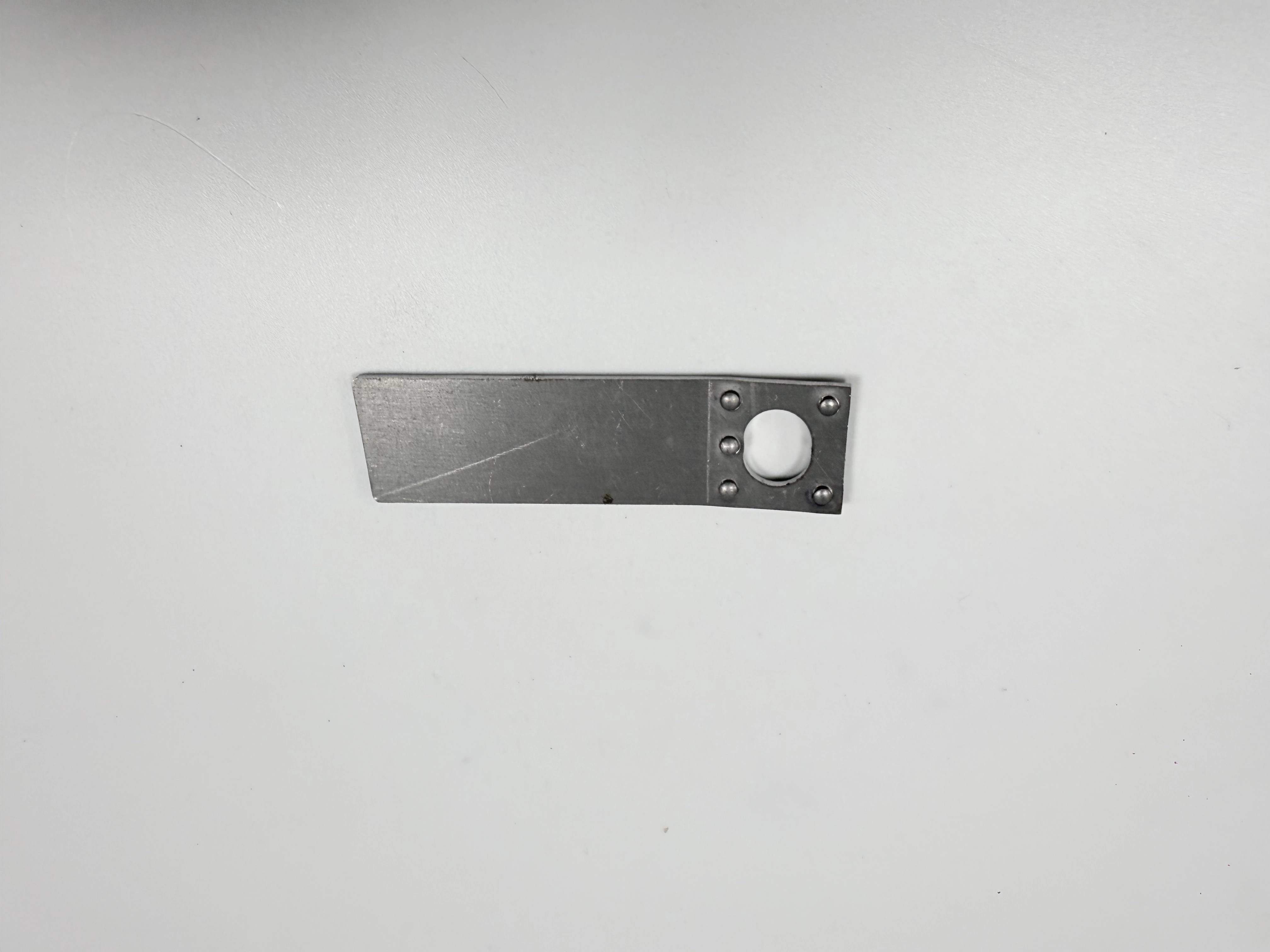
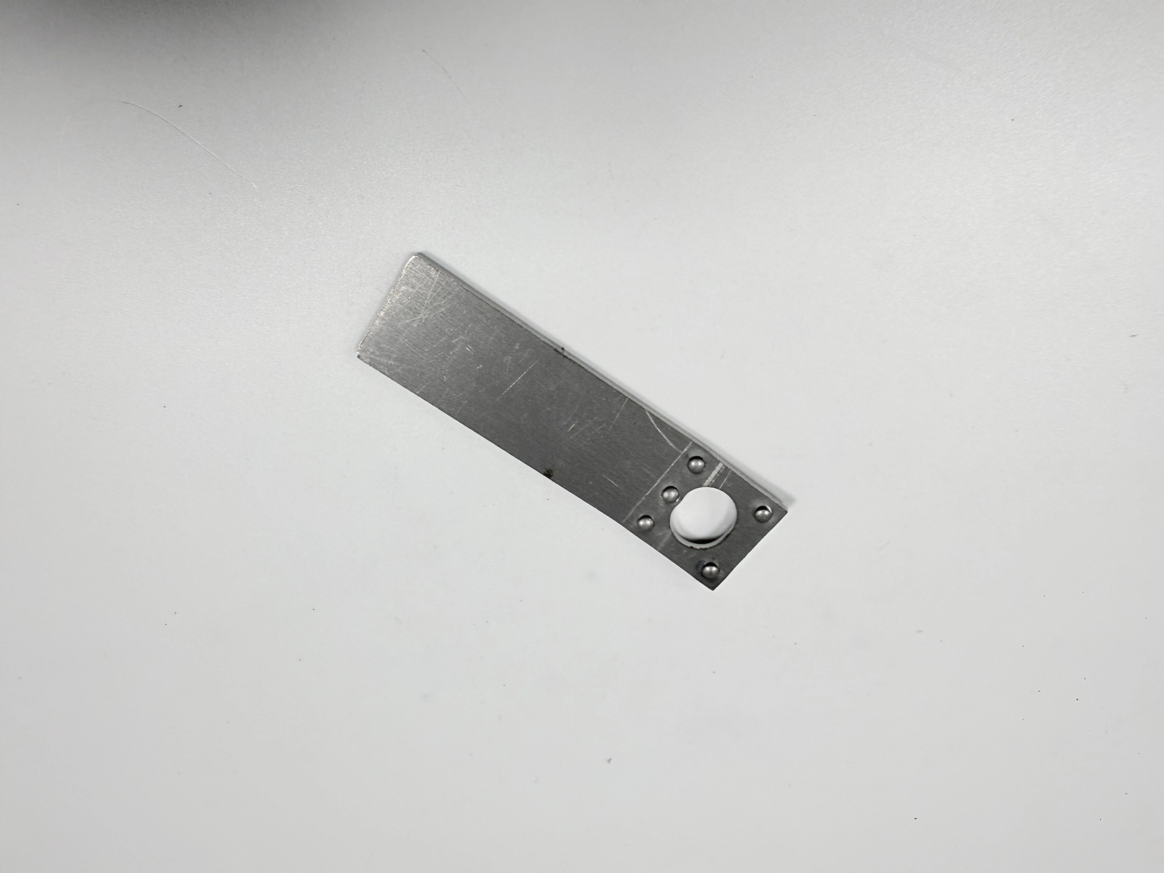
The paired views show one long flat plate with a large rectangular body, an end hole, and a cluster of smaller circular features near the same end. The views confirm the same physical product and different angles. They do not reveal size, material, thickness, hole tolerance, load, or production status. Use the visible shape to ask about sag, support spacing, hole access, and end-pattern registration; use controlled records for all engineering claims.
Plan Support Before the Part Is Loaded
Large-part stability begins with the support map. Record contact points, support height, compliant pads, clamps, vacuum or magnetic methods where applicable, and the datum sequence. Support should limit sag and movement without forcing the part into an artificial shape that disappears after release. A support drawing or fixture planning reference can structure the review, but the actual part stiffness, mass distribution, and surface condition control the result.
Measure the plate in its loading state before cutting. Record flatness, twist, local damage, burrs, and contact conditions. If the part is thin, long, or asymmetric, compare restrained and free behavior where the function requires it. Do not use a nominal support grid from another size or material as proof for this component. Link the pre-load result to unit identity and drawing revision.
Define Support Reactions
State what happens if a support point is high, low, dirty, worn, or inaccessible. A reaction may require cleaning, shim adjustment, a new support qualification, expanded inspection, or an approved alternate setup. Preserve the original measurement and support condition. If a clamp is moved, record the affected features and repeat the checks sensitive to bending or twist. Stability is a controlled state, not a visual impression.
Build a Jig Datum That Survives Reorientation
Name primary, secondary, and tertiary datums, contact order, clamp direction, orientation marks, and witness features. A convenient edge or fixture stop may be repeatable while still being unrelated to the functional hole pattern. If an auxiliary surface is used to gain access, document the transformation to the drawing frame and the tolerance consumed. If the datum scheme is unclear, obtain an approved interpretation before programming.
Large plates often require flipping or rotating. Define which features preserve the frame and which are re-established after the move. A milling route reference can frame the faces and pockets that precede boring, while a CNC machining reference can frame the broader route. Neither replaces a transfer check on the actual setup.
Verify Datum Transfer on the Actual Plate
Run a transfer check after a flip, fixture change, locator replacement, machine move, or program revision. Use a representative plate and witness features tied to the hole pattern. Record setup revision, contact sequence, sample identity, temperature, and result. A calibration artifact can show instrument readiness, but it cannot demonstrate how a long plate seats or bends. Hold the affected range if the transfer cannot be reconciled.
Manage Hole Access and Tool Reach
Map the path from holder to every hole, counterbore, shoulder, and relief. Include approach, retract, clearance, chip evacuation, coolant delivery, and probe access. A hole near a clamp or edge may require a different orientation than a central hole. State whether the tool enters through a free face, a slot, or an interrupted surface. Machine travel and spindle power do not prove that a long tool will remain aligned.
Choose tool projection, holder support, cutting method, and pass sequence for the actual reach and material state. Record the signals that indicate deflection, chatter, or tool wear. A turning reference may help frame a cylindrical predecessor, but jig boring scope remains controlled by the hole pattern and datum. Do not claim a universal deep-hole capability from a machine specification.
React to Access and Deflection Signals
Stop or contain the affected unit when the holder approaches a clamp, chips remain in a blind feature, chatter appears, or a hole drifts from the first-piece result. Preserve tool, holder, support, and program records. Review projection, entry stock, fixture stiffness, coolant, and alignment. Rework requires an approved stock and geometry review; another pass can consume margin without restoring the hole relationship.
Control Thermal and Material State
Large parts can develop temperature gradients from cutting, coolant, handling, or the surrounding machine. State stabilization time, room and part temperature, coolant condition, and measurement timing. If the plate is heat-treated, welded, coated, or stress-relieved, record the transition and repeat the checks that can move hole location or flatness. A material certificate supports identity within scope; it does not prove the behavior of this geometry.
Cleaning and coating can change seating or dimensions. Define whether the hole pattern is accepted as-bored, washed, coated, or assembled. If an outside process follows boring, record processor, specification, batch, masking, and before-and-after checks. A metal finishing reference can frame the state transition, but it does not replace final measurement.
Write a Thermal Reaction Rule
Set a reaction for unexpected drift, discoloration, coolant loss, roughness change, or movement after unclamping. Hold the affected units, bound the process range, and decide whether expanded inspection, rework, replacement, or deviation is authorized. Keep original and post-process values together. Do not average a warm measurement with a stabilized measurement or replace a failed result with a later reading.
Separate Hole Size, Location, and Form Evidence
Measure diameter with a defined gauge and depth or section plan. Measure position, perpendicularity, and pattern relationships in the drawing datum frame. Measure flatness, twist, and local form under the stated support condition. A pin fit can indicate clearance under one state; it does not prove axis location, perpendicularity, or full depth. A CMM report depends on alignment, probe access, temperature, and restraint. State those fields for every result.
For an end hole cluster, identify whether the pattern is controlled from the long edge, an end face, or a derived center. Record angular orientation, edge distance, counterbore depth, and any shared axis. If a probe cannot reach the bottom or an edge is obstructed, document the unmeasured region and alternate evidence. Keep raw data linked to unit and revision.
Use an Inspection Evidence Table
| Characteristic | Method and state | Boundary |
|---|---|---|
| Hole diameter | Defined depth, gauge, temperature | Not position or pattern proof |
| Hole position | Datum frame, probe or CMM alignment | Not fit or material proof |
| Flatness and twist | Support, restraint, section and instrument | Not hole-axis proof |
| Functional fit | Specified hardware, load and assembly state | Not all geometry proof |
The table keeps evidence bounded. A quality inspection reference can assign ownership, while the drawing controls acceptance. If a functional frame is assembled, record hardware identity, fastener state, load, and temperature so the result is reproducible.
Control the Machining Sequence
Sequence roughing, datum creation, drilling, boring, deburring, cleaning, and inspection so each operation leaves a known state for the next. A large plate may require roughing on both sides before a stable finish setup. Define when hole patterns are created, when support changes, and when first-piece evidence is reviewed. A grinding reference can frame a later flatness operation, but its state must be separate from hole-location acceptance.
Use measurable triggers for tool change, fixture adjustment, support replacement, material change, coolant change, and program revision. Record the affected range and recheck. Do not rely on a machine reset or nominal repeatability to prove that the pattern remained stable. A process trend is a prompt for investigation, not a release result unless the plan defines it.
Control Outside Processes and Delivered State
Heat treatment, coating, cleaning, welding, assembly, and packaging can alter a large plate's flatness, hole condition, or seating. State processor, specification, batch, masking, before-and-after dimensions, certificates, and reinspection. Distinguish as-machined from coated or assembled records. If the delivered part is bolted to a frame, define the frame, fasteners, torque, support, and acceptance method.
A certificate supports the processor claim within scope; it does not replace final geometry or functional evidence. If the part returns with new marks, residue, or a changed support condition, hold release until identity and affected CTQs are reconciled. Preserve the original pre-process measurements to show what changed.
Write a Large-Part Jig Boring RFQ
Attach controlled drawing and model revisions, material and condition, plate dimensions, hole function, datum scheme, support limits, entry stock, tool access, hole depths, counterbores, CTQs, inspection state, sampling, records, outside processing, packaging, and milestones. Ask suppliers to state support map, clamp sequence, orientation transfers, tool projection, chip control, thermal stabilization, inaccessible regions, and reaction triggers.
Separate programming, fixture, support, tooling, first-piece, inspection, rework review, outside processing, packaging, and freight costs. Ask how the supplier will verify the end pattern after a flip and how the affected range is bounded after a support or tool change. Request a redacted setup and inspection format with unit identity and revision. A quote that lists only a hole tolerance and cycle time is not comparable.
Screen the Supplier on Stability Evidence
Compare whether each candidate explains large-part support, datum transfer, access, deflection, thermal state, hole-pattern inspection, outside-process handoff, and change control. A machine table, work-envelope number, or generic “jig boring accuracy” phrase is not proof for this plate.
Ask for an anonymized stability study, setup record, or first-piece format tied to similar length, support, and hole-pattern risk. Prefer responses that state limitations, owners, sample basis, and restart rules. If a supplier cannot show how the plate is supported and how the end pattern is measured after reorientation, keep that gap open before selecting on price.
Release the Large Part With Explicit Boundaries
Release when revision, material state, support, datum transfer, tool access, hole size and position, flatness, functional checks, outside-process records, packaging, and deviations agree. Hold when a measurement belongs to another support state, a hole region is inaccessible, a flip is unverified, or the unit cannot be traced to the setup.
Large-part jig boring succeeds when stability and evidence are planned together. The paired plate views are geometry prompts, not proof of size, material, capacity, or application. Let the drawing, actual support map, measured pattern, and lot-linked records determine acceptance. A CNC route review can support broader planning while the jig-boring inspection frame controls release.
For a long plate, the support map should be treated as part of the process definition. Record how the plate is loaded, where gravity can create sag, which pads carry weight, and which contacts establish the functional frame. If the part is rotated, record the unloading and reloading sequence rather than assuming that the same coordinates recreate the same shape. A fixture engineering reference can help organize these questions, but only an actual support check shows whether the plate seated as intended.
Thermal drift deserves its own decision rule. A large body can warm near the cut while a remote edge remains cooler, so a pattern measured immediately after machining may not match a stabilized result. State coolant removal, soak time, room temperature, part temperature, and the release state. If the plate is coated, welded, heat-treated, or bolted to a frame later, define which holes or faces must be rechecked. A measurement planning reference can organize the record fields, but it cannot replace the defined datum and state.
Inspection transfer should be visible to purchasing as well as quality. Ask where the supplier establishes the pattern origin, how the end-hole cluster is correlated after a flip, and what evidence covers an underside or obstructed feature. A milling process reference can frame the upstream faces and slots that affect access. The released result still depends on the controlled drawing, actual support, actual setup revision, and unit-linked measurement files.
A large-part route also needs a clear boundary between fixture capability and product evidence. A support may repeat a setup while a hole pattern still drifts because the plate relaxed, a locator changed, or a tool deflected. Record the setup verification, then record the product measurement in the same coordinate frame. If the method cannot reach a hole bottom or an underside face, write the limitation and the approved alternate check. This makes the acceptance decision auditable instead of relying on a broad machine claim.
Plan the buyer's review around likely failure modes: sag between pads, twist after unclamping, chip under a contact, edge-distance loss after pattern shift, chatter at a counterbore, or a warm plate measured before stabilization. Each mode needs a trigger, a containment boundary, and an owner. When a change occurs, preserve the prior result and identify the units requiring reinspection. The objective is not to eliminate every process variation; it is to make the functional hole pattern and its evidence resilient to the variations that matter.
For repeat work, retain the support map, transfer check, first-piece pattern, and reaction history as a route baseline. A baseline is useful only within the same revision, material, support, tool, and measurement state. If any of those inputs change, treat the baseline as evidence to review rather than a guarantee to copy. This discipline keeps large-part jig boring decisions tied to the actual plate and the actual lot.
FAQ