How Can Hole-Pattern Drift Be Checked After a Large-Part Setup Change?
How Can Hole-Pattern Drift Be Checked After a Large-Part Setup Change?
Hole-pattern drift after a large-part setup change should be checked with a controlled datum transfer, representative witness features, and separate measurements of hole size, position, orientation, and plate movement. A first-piece result from the old fixture cannot validate a new support, locator, machine, or orientation. The buyer should bound the affected units, preserve the original data, and repeat every characteristic sensitive to the change before release.
Define Drift Against the Drawing
List the pattern relationships that matter: pitch, edge distance, true position, hole axis, perpendicularity, counterbore depth, and relation to the functional datum. Separate those from diameter and flatness. A hole can be the correct size while the pattern is shifted or rotated. State whether the plate is measured free, restrained, or assembled, and use the same frame for before-and-after comparison.
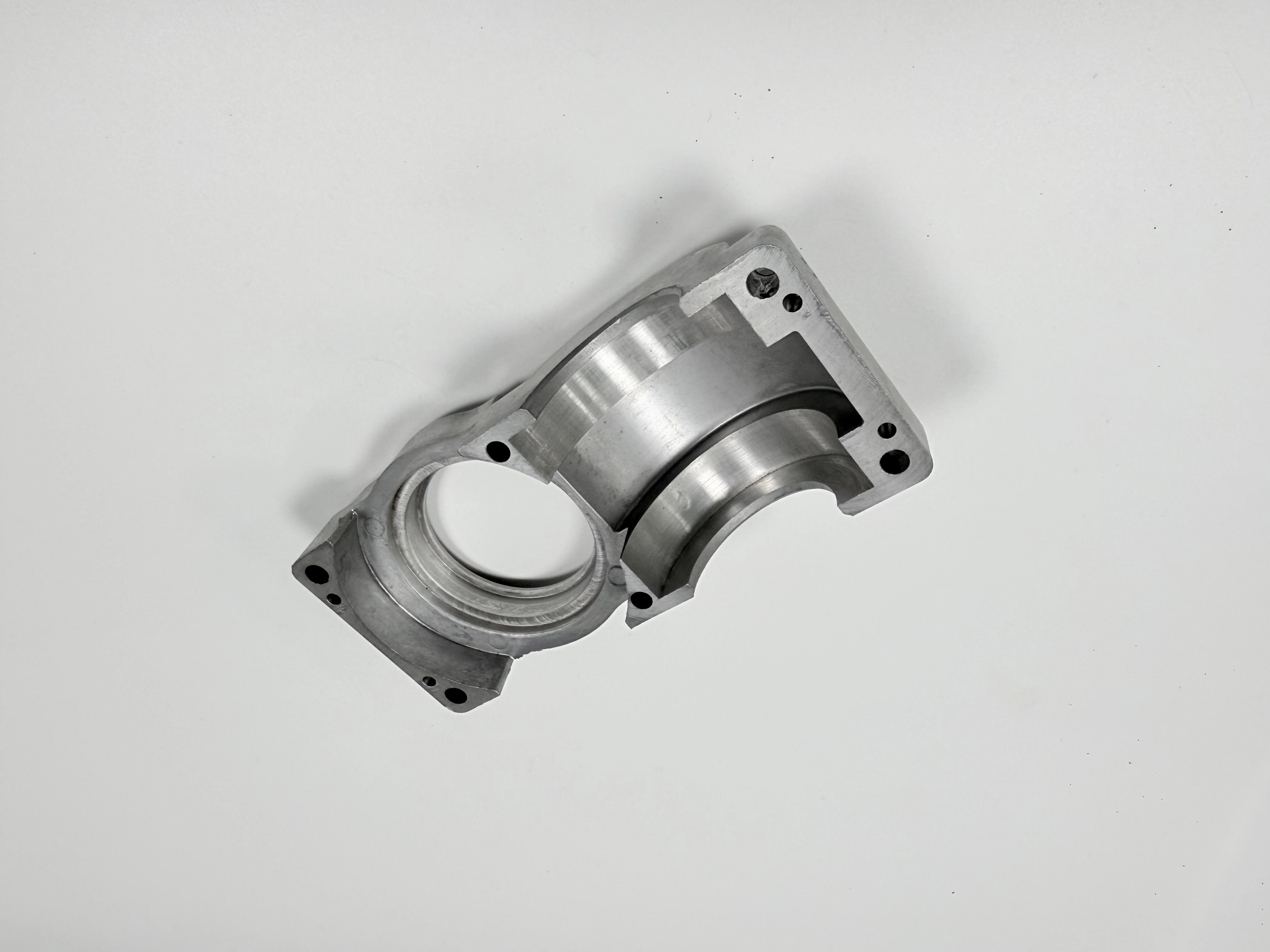
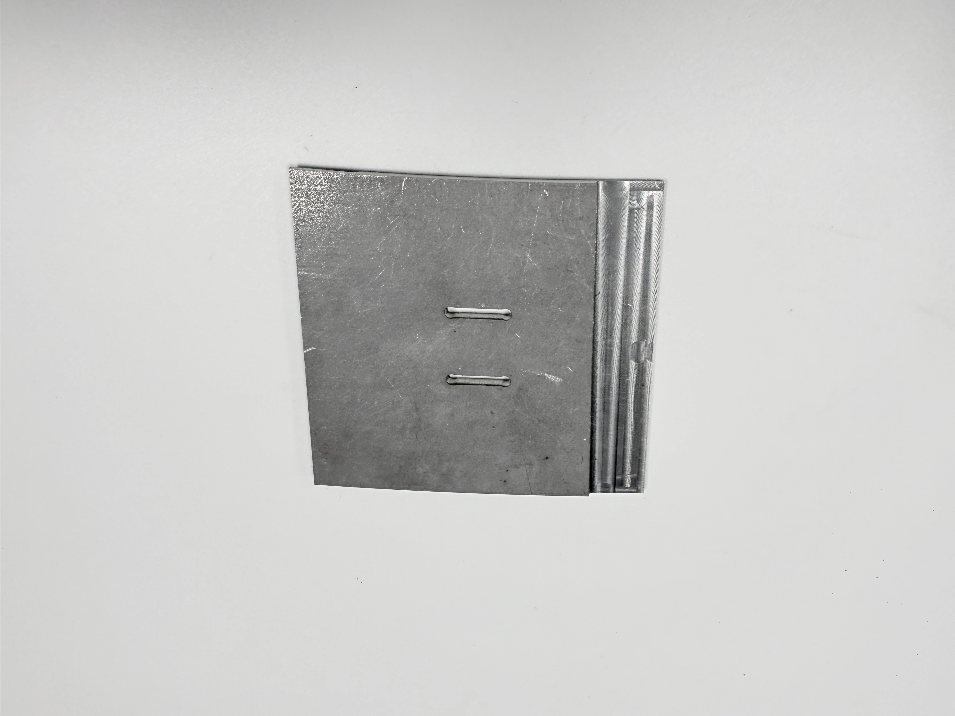
The paired images show one long flat plate with an end hole and a cluster of smaller circular features. They support visible geometry and different viewing angles only. They do not prove dimensions, material, tolerance, or drift. Use the controlled model, marked datum, and actual measurement records for the decision.
Classify the Setup Change
Record whether the change concerns fixture, support pad, locator, clamp, machine, tool holder, program, probing routine, material heat, coolant, or orientation. Each can affect a different characteristic. A locator change may move the datum; a support change may alter sag; a tool change may affect diameter or perpendicularity; a probing change may alter the reported frame. State the effective time and affected unit range.
Do not treat a reset, operator sign-off, or machine warm-up as a complete validation. Define the checks required for the change class and the owner who approves restart. Keep the prior and new setup identifiers visible. If the change occurs between parts, use serial, lot, time, and setup records to bound exposure.
Use Witness Features and Transfer Checks
Select witness holes, edges, or reference pads that connect the setup to the functional pattern. Measure them before and after reorientation or fixture replacement. Record contact sequence, support, clamp direction, temperature, instrument, alignment, and unit identity. A calibration artifact can show the instrument is ready but cannot show how a long plate seats.
If a witness result moves, hold the affected units and investigate seating, support, locator condition, burrs, and datum interpretation. Do not average a moved value with an old value. A repeat after reseating is useful only when the original condition and reason for the repeat remain in the record.
Measure Pattern and Plate Separately
Evaluate hole position and orientation in the drawing datum frame. Evaluate diameter at defined depth and temperature. Evaluate flatness, twist, and local form under the stated support. A CMM result depends on alignment and probe access; a pin fit indicates a condition under its hardware and state. Neither method proves every pattern relationship without a defined plan.
For an end cluster, record reference edge, pattern origin, pitch, angular orientation, counterbore, and edge distance. If a hole or underside feature is inaccessible, identify the alternate method and its limitation. Keep raw coordinates, reports, and setup data linked to the same unit and revision.
Control Time and Thermal State
Large plates can move as they warm, cool, or relax after unclamping. State stabilization, coolant removal, room temperature, part temperature, and measurement timing. If the part is welded, heat-treated, coated, or assembled after boring, record the state transition and repeat sensitive checks. A time gap between setup and measurement can be a process variable.
Compare before and after only when state, support, datum, and method match. If they do not, describe the difference and obtain an approved interpretation. Do not call a location shift process drift when the measurement frame changed. Preserve the records that show both states.
React to Confirmed Drift
Contain the lot when drift exceeds the drawing requirement or cannot be bounded. Review support, locator, clamp, tool, program, temperature, and measurement events. Decide whether expanded inspection, rework, replacement, or deviation is authorized. Re-boring or enlarging holes can alter fit, edge distance, and structural margin, so it is not an automatic correction.
After corrective action, repeat the affected pattern and functional checks. Keep the failed result, correction, and approval together. If the drift source remains unknown, do not release on a single successful sample. Expand inspection until the acceptance owner can justify the population boundary.
Specify Drift Checks in the RFQ
Provide pattern datums, witness features, support state, setup-change classes, required measurements, temperature, sampling, raw-data format, reaction authority, and record retention. Ask suppliers to define first-piece checks after fixture, locator, machine, tool, program, material, coolant, or orientation changes. Require clear unit-range traceability.
Request a redacted transfer-check format with old and new setup identifiers. A supplier statement that the machine is repeatable is not equivalent to product drift evidence. Compare quotes after the change-control and reinspection scope is explicit.
Buyer Action
Approve the release when the change class, affected range, datum transfer, witness result, pattern measurements, state, and corrective reaction are documented. Hold when a new setup is accepted by assumption or when position, size, and plate movement are conflated. Drift control is a traceable comparison of the actual plate under matched conditions.