How Should a Large Plate Be Supported for Jig Boring?
How Should a Large Plate Be Supported for Jig Boring?
A large plate should be supported for jig boring with a documented contact map that limits sag and movement without forcing the plate into a shape that disappears after unclamping. Support height, spacing, pads, clamps, datum sequence, and measurement state must match the functional hole pattern. A plate that appears flat on a machine can relax, twist, or shift when the support changes. The buyer should define whether the released part is free, restrained, assembled, or bolted to a frame and require evidence in that state.
Map Stiffness and Geometry
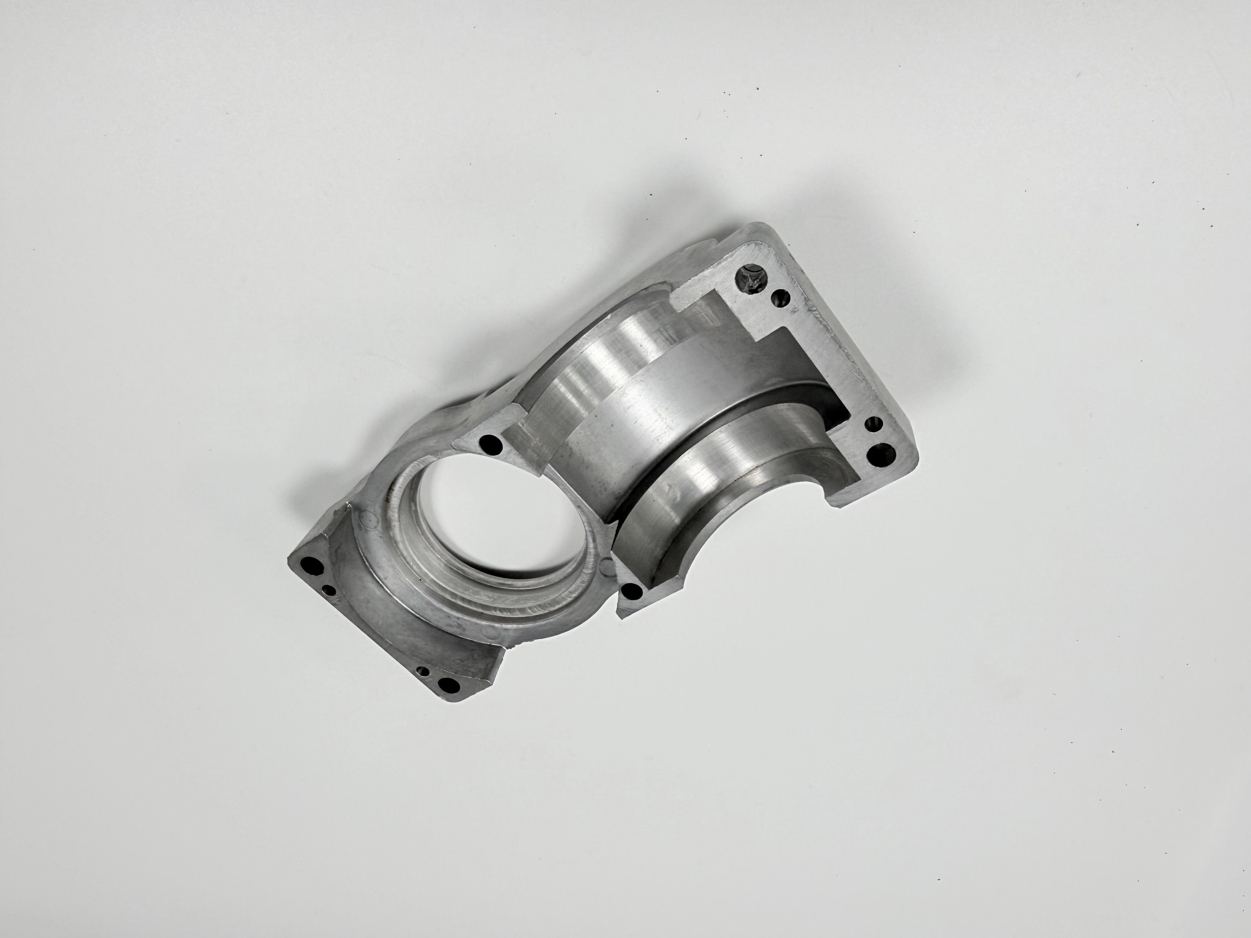
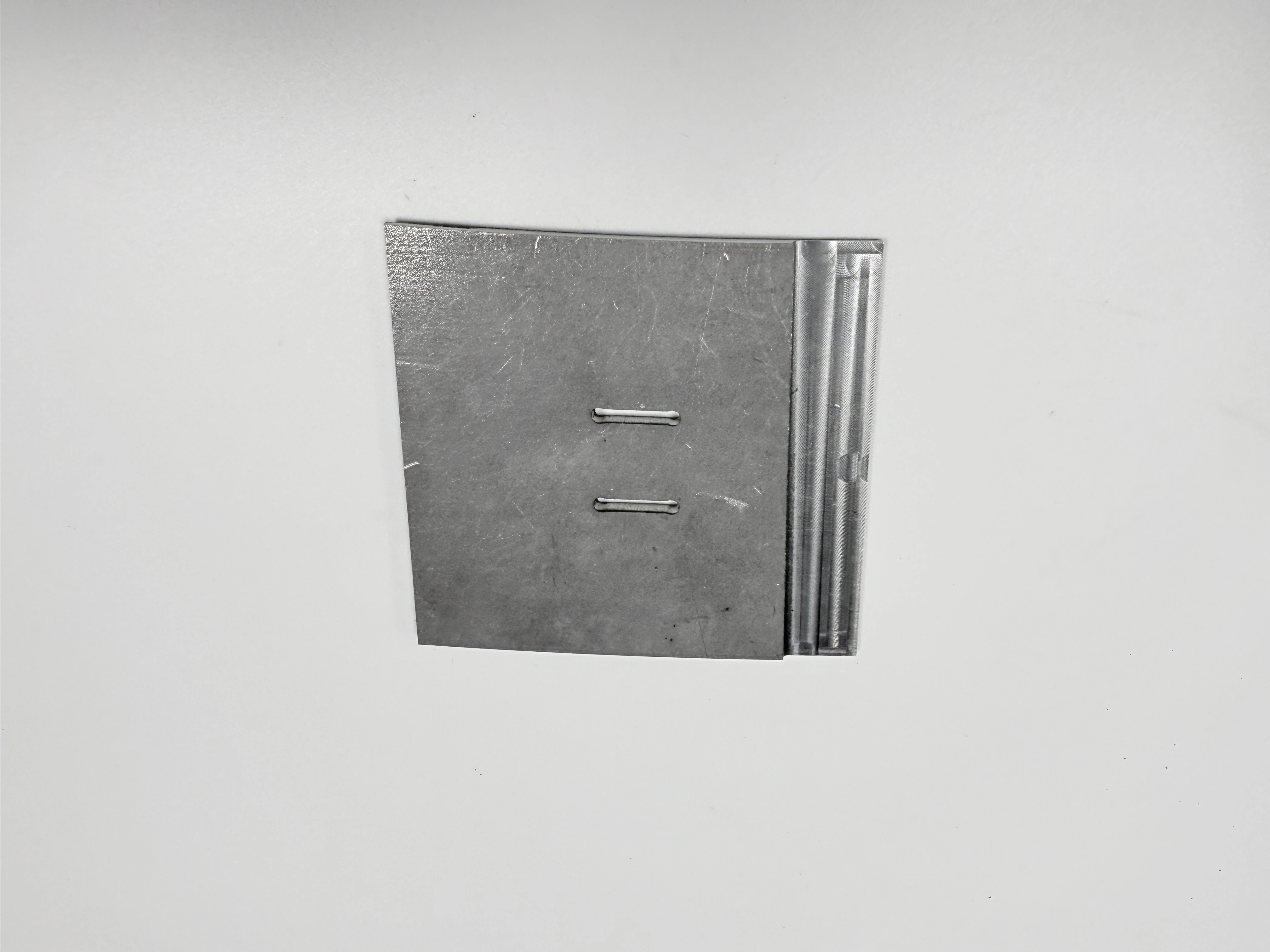
Use the drawing and model to identify length, width, thickness, pockets, slots, end patterns, and thin regions. Mark the faces and holes that control assembly. The paired views show one long rectangular plate with a circular end hole and several smaller holes; they confirm visible geometry only. They do not establish dimensions, material, load, tolerance, or stiffness. Use a measured part and approved model for support decisions.
Before loading, record flatness, twist, burrs, damage, and the condition of the datum faces. Note material designation, heat treatment, and any welding or coating that can change movement. If the plate is thin or asymmetric, compare free and restrained readings when function requires both. A nominal support layout from another size or material is not proof for the current geometry.
Define Contact and Clamp Sequence
Name primary, secondary, and tertiary contacts and state which is established first. Record support points, compliant elements, clamp direction, clamp load control, and seating checks. Excessive force can bend a plate; insufficient force can permit vibration or movement. Clean chips, burrs, coolant, and coating from contact faces. If a locator, shim, or pad is replaced, treat it as a change until its effect is verified.
Do not let the clamp sequence be an operator preference. Mark orientation and witness features so a second setup can reproduce the condition. If a clamp blocks a hole or probe, state the alternate orientation and the transfer check after the move. A rigid fixture can still create a wrong datum if its contacts do not represent the drawing.
Verify Support Before Cutting
Run a support verification with the actual plate or a representative unit. Record support identifier, contact order, seating result, temperature, restraint, and measured witness features. A calibration artifact demonstrates instrument readiness but not how a long plate bends. Check the end hole pattern and a central or edge feature when they carry the datum relationship. Hold the job if contact cannot be reconciled.
Set reactions for a high or low support, damaged pad, unstable clamp, unexpected gap, or movement during probing. Options may include cleaning, shim adjustment, support qualification, expanded inspection, alternate setup, or an approved deviation. Preserve the original condition and measurement. Do not overwrite a failed support check with a later reseated value.
Control Temperature and State
Large plates can develop gradients from cutting, coolant, handling, or the surrounding machine. State stabilization time, room and part temperature, coolant condition, and measurement timing. Heat treatment, welding, stress relief, coating, and long storage can change flatness or hole location. Record each transition and repeat sensitive checks before release.
Cleaning and packaging can change seating. If the delivered plate is coated, assembled, or bolted to a frame, define the recheck or correlation to the as-machined state. A certificate supports material or processor identity within scope; it does not prove flatness or hole location. Keep pre-process and post-process records linked to the unit.
Balance Support With Tool Access
Support points must hold the plate without blocking tool approach, retract, chip evacuation, coolant, or probe access. Map each clamp and pad against the hole pattern, counterbores, edges, and any underside feature. If the plate must be flipped, identify which contacts preserve the datum and which are re-established. Record orientation marks and a transfer check after each move.
A machine envelope does not prove that a holder can reach every hole under the supported state. Check projection, clearance, deflection signals, and access to the deepest feature. If an area is inaccessible, define the alternate method and its evidence boundary before cutting. Do not infer access from the photograph.
React to Movement and Drift
Contain the unit when a hole drifts, the plate moves after unclamping, chatter appears, or a support condition changes. Preserve setup, tool, datum, and measurement records. Review stock distribution, clamp force, support height, temperature, tool projection, and program. Rework requires an approved stock and geometry review; another pass may consume margin without restoring the pattern.
When a correction is made, repeat flatness, hole position, affected diameters, and functional checks in the required state. If the affected range cannot be bounded by support event or time, expand inspection. Release only after the acceptance owner confirms that the support state represents delivery.
Specify Support in the RFQ
Provide plate dimensions, material and condition, datum scheme, functional hole pattern, support limits, clamp restrictions, temperature state, orientation sequence, tool access, inspection method, sampling, records, and reaction authority. Ask suppliers to show contact map, seating verification, transfer checks, support-change triggers, and the free or restrained state accepted at release.
Require notification before changing fixture, pads, locators, clamp sequence, machine, tool, program, coolant, material heat, or measurement method. Request a redacted setup record with unit identity and revision. A quote that lists only a hole tolerance or machine table is incomplete when support stability controls the result.
Buyer Action
Approve the support plan when contact sequence, stiffness, access, temperature, transfer, reaction, and release state are explicit. Hold it when the plate is forced into an unverified shape, a flip lacks a transfer check, or the functional state is unknown. Large-part jig boring depends on a support condition that is measured, repeatable, and traceable to the delivered geometry.