From Casting to Final Fit: CNC Turning a Closed Pump Impeller
From Casting to Final Fit: CNC Turning a Closed Pump Impeller
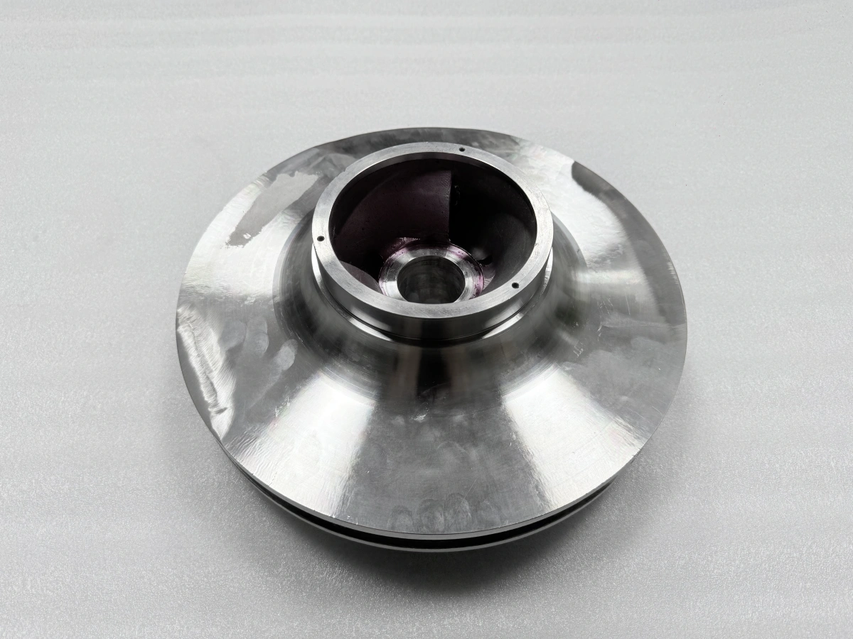
This small-batch pump-component project brings a closed impeller and its wear rings into one machining plan. The impeller is not simply a round part that happens to fit a lathe: casting forms its enclosed flow passages, while the bore, faces, and ring interfaces need a common working axis. For Neway's engineers, closed impeller CNC machining starts with three decisions: preserve the hydraulic geometry, establish usable datums, and reserve the right surfaces for finishing. The project requirements illustrate how we approach a proposed route for this type of industrial equipment component.
Let Casting Form the Flow Geometry
The first decision is to separate hydraulic shape from mechanical interface. A closed impeller contains internal passages between two shrouds. Those passages are governed by the casting route and cannot be approached like open pockets on a milled plate. The machining plan should therefore begin with a protected-zone map: casting-formed passage walls and shrouds remain outside the turning scope unless the released drawing explicitly says otherwise, while accessible circular faces, bores, seats, and shoulders become candidates for later finishing.
The impeller is therefore a casting with selected machined interfaces, not a shape that needs to be recreated entirely by turning. Broader CNC machining can support secondary features, but each operation should be tied to an accessible feature and a drawing requirement. Starting from that distinction helps avoid unnecessary stock removal near the flow path and keeps the route focused on fit, location, and assembly. It also gives the casting supplier a clearer stock target: enough material for cleanup at the machining zones without loading extra allowance onto surfaces that should retain their cast form.
Turn the Drawing Into an Interface Map
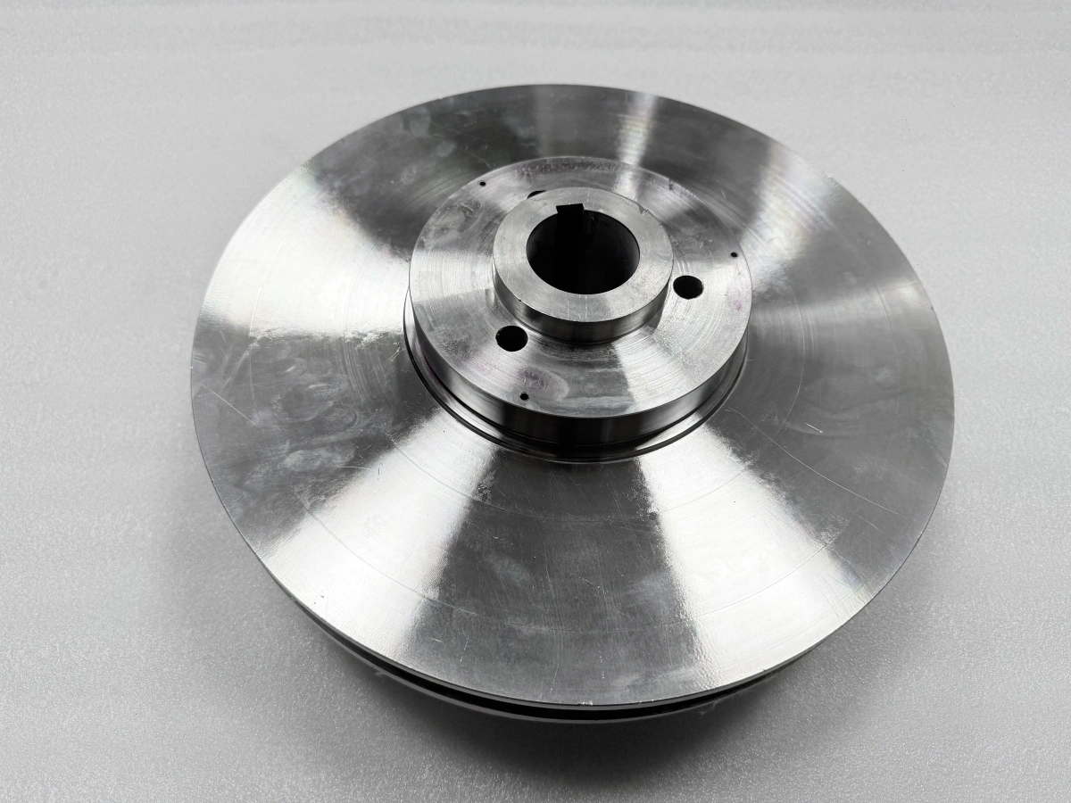
Before selecting jaws, tools, or speeds, the drawing needs to be read as a set of functional relationships. The central bore establishes a likely rotational reference. Adjacent faces can locate the impeller axially. Ring seats, shoulders, and outside circular surfaces may control the relationship between the rotating body and stationary pump components. A keyway or hole pattern can add clocking or attachment requirements, but it should not be assumed to define the main axis.
The material callouts belong in the same map. The project drawing specifies WCB for the impeller body and CA6NM for the wear rings; the machining plan needs both the specified grade and the documented starting condition. The body and rings may respond differently to cutting, clamping, and finishing, which is another reason to define their interface instead of applying one generic cutting recipe. Tool choice, edge preparation, cutting data, and allowance should follow the actual documented material condition available for production.
Build the Datum Strategy Around Final Fit
The most convenient raw surface is not automatically the right datum. Casting variation can make an as-cast diameter easy to grip but unreliable as a functional reference. A stronger precision machining plan identifies which bore, face, or pilot surface should establish the axis, which feature controls axial location, and how that relationship will survive a reversal or a later assembly step.
A practical sequence may use an early setup to create or qualify reference surfaces, then use those references to finish the functional interfaces. The exact sequence remains drawing-dependent. What matters is that every transfer has a named witness: a bore, face, or diameter that can be rechecked after reclamping. The setup record should also distinguish support from location. A pad may prevent the shroud from deflecting without being allowed to redefine the axis. That distinction becomes especially important on a broad, disc-like component where clamping pressure can change the apparent relationship while the part is still held.
Treat the Impeller and Wear Rings as a Fit System
Wear rings should not be planned as isolated loose parts when their useful geometry depends on the assembled impeller. The drawing-defined ring seats, mating faces, and final running interfaces form a chain. If each element is finished separately, the accumulated location error can be different from the relationship seen after assembly. For that reason, finish-machining after assembly may be selected when the common axis and final fit need to be controlled in the assembled state.
The best route depends on the released drawing, available stock, assembly method, support strategy, and the influence of later cutting on neighboring features. If assembly finishing is selected, the process plan should name what is measured before assembly, what retains controlled allowance, which datum is recovered afterward, and which interfaces are checked again. If separate finishing is sufficient, the ring-to-body tolerance chain still needs to be calculated and recorded. Making that choice early helps the machinist reserve stock in the right locations and prevents a nominally finished ring from becoming the wrong reference for the completed assembly.
Use Turning, Boring, and Drilling for Different Jobs
Rotational faces and outside diameters are natural candidates for CNC turning, but the toolpath still needs a stable axis and enough remaining stock to clean up the intended surface. Roughing and finishing can be separated so the engineer can observe how the casting seats and how the component responds after material removal. The final cutting cycle should protect the functional relationship, not merely improve appearance.
Internal geometry may call for CNC boring when bore size and axis need to be related to a turned face or seat. Boring is not automatic proof of that relationship; the setup and measurement datum must match the drawing. Likewise, CNC drilling can create secondary holes where the design requires them, but hole size alone does not establish clocking or position. The route should state whether holes are located from the bore axis, a keyway, a face, or another defined reference.
Manage Casting Stock Before It Reaches the Finish Tool
Casting stock is rarely distributed as evenly as bar stock. The process plan should check whether the intended reference surfaces have enough cleanup allowance and whether an offset between cast and functional axes will consume stock on one side first. A light witness cut can reveal seating or stock-distribution problems before the route commits to the final datum. The engineer can then decide whether to adjust location within the drawing's permitted geometry, revise the setup, or pause for a casting review.
Roughing should also respect the impeller's broad shrouds. Removing material from one side, clamping near a thin region, or supporting only the hub can change how the component sits. Balanced stock removal, staged depth, sensible tool engagement, and intermediate unclamped checks can make that movement visible. The goal is not to chase every temporary reading; it is to reserve enough material so the final interfaces can be created after the main cutting loads and seating changes have already occurred.
Support the Shrouds Without Redefining the Axis
A closed impeller combines a stiff hub with wider disc-like surfaces. Workholding needs enough grip for interrupted or changing engagement, yet excessive jaw or support load can distort a shroud or tilt the hub. The setup drawing should identify locator contacts, clamp contacts, and support contacts separately. It should also show where chips can collect, because a chip under a support can shift the part even when the fixture feels secure.
Support conditions matter during measurement as well as cutting. A reading taken while the part is heavily clamped may not describe the relaxed component. For sensitive bore-to-face or ring-seat relationships, the route can define when to inspect in the machine, when to release and reseat, and when to measure in the assembled state. Using the same functional datum concept across these states makes changes easier to interpret and reduces the risk of correcting a feature that only appeared displaced under fixture load.
Time Final Finishing Around the Assembly State
The timing of a final cut matters as much as the tool. Assembly, joining, stress redistribution, or another specified step can shift the working relationship. Finishing too early may preserve a relationship that no longer exists in the final component, while unnecessary re-machining can consume stock and add another setup transfer. The engineer should therefore define the component state required for each final interface before setting the operation sequence.
A useful pre-finish checkpoint confirms the active revision, component identity, assembly condition, recoverable datum, support method, and remaining allowance. The final dimensional method should then reference that same state. This keeps the route practical: the machining team knows what must be stable before the last cut, the assembly team knows which surfaces must be protected, and the inspection team knows which datum relationship the drawing asks it to evaluate.
Use Records to Preserve Engineering Context
Useful records allow the next stage to understand what the previous stage established. A route traveler can identify the operation and component state. A dimensional record can identify the characteristic, method, instrument, and reference used, provided those fields are actually documented. An assembly record can define which elements were together when a relationship was checked. Nondestructive examination records can state method and coverage. A balancing record can identify the configuration to which it applies.
This is where quality assurance supports engineering rather than simply adding paperwork. Material, casting, machining, assembly, nondestructive examination, and balancing records answer different questions. The route can list which record belongs at each handoff, the component state it describes, and who uses it for the next decision. That makes a later review faster because the team does not have to reconstruct whether a measurement belongs to the loose ring, the machined body, or the assembled impeller.
Keep the Small-Batch Route Deliberate
For low-volume manufacturing, the temptation is to compress preparation because the batch is small. A better strategy is to make the route lean but explicit. Confirm the released geometry, map the critical interfaces, define stock and datum transfers, and decide which checks belong at the first setup, after reversal, after assembly, and at final state. This concentrates effort on the relationships that control fit without imposing the same inspection burden on every visible surface.
The result is a repeatable decision framework. Casting forms the enclosed flow geometry. Machining addresses the specified accessible interfaces. Datums follow assembly function. Wear-ring finishing is selected from the tolerance chain and component state. Turning, boring, and drilling each have defined boundaries. Records preserve the meaning of those choices. Together, these decisions make a proposed route easier to compare, refine, and release against the controlled drawing.
Review the Interfaces Before Releasing the Route
A useful review starts with the impeller drawing and the mating-component information, then traces the bore, faces, ring seats, shoulders, keyway, holes, and final assembly state through one datum chain. Neway can use that package to identify the proposed turning scope, conditional assembly-finishing steps, and the records needed at each handoff. Share the current impeller and mating-component drawings to begin an interface-focused manufacturing review.
FAQ