Stainless Steel CNC Machining: 8 Common Considerations
Introduction: Challenges and Value of Stainless Steel CNC Machining
The eight common considerations in stainless steel CNC machining are material grade, tooling, cutting parameters, workholding, work hardening, chip evacuation, geometry planning, and post-processing. These factors decide whether a part holds tolerance, resists corrosion, avoids burr problems, and remains cost-effective from prototype to production. A useful review of stainless steel CNC machining services should start with the service environment and drawing requirements, then connect them to grade selection, setup strategy, inspection, and finishing.
Stainless steel is valuable because it can combine corrosion resistance, strength, cleanability, appearance, and long service life. It is also demanding because many grades conduct heat poorly, work harden under rubbing, form tough chips, and expose weak fixtures or long tools. Buyers should provide the exact grade or performance requirement, stock condition, heat-treatment state, critical dimensions, datum scheme, wall thickness, surface finish, burr limits, post-processing needs, quantity, and inspection method. Those inputs allow the machining route to be checked before cost, lead time, and quality assumptions become fixed. The RFQ should also identify whether the buyer needs a visual prototype, a functional prototype, a corrosion sample, or a production-intent part. Each purpose changes material choice, inspection depth, finishing sequence, and acceptable risk. If the part will be used for sealing, medical cleaning, food contact, aerospace fixtures, hydraulic flow, or outdoor exposure, the RFQ should also explain the failure that must be avoided.
Consideration 1: Selecting the Most Suitable Stainless Steel Grade
The stainless steel grade should be selected from the operating environment first, then checked against machinability, strength, heat treatment, finishing, and cost. Grade names are not interchangeable. Austenitic, martensitic, ferritic, and precipitation-hardening stainless steels respond differently to cutting heat, work hardening, tool wear, passivation, welding, and corrosion exposure. A drawing that only says “stainless steel” is not enough for a reliable quote. The RFQ should state whether the part faces chlorides, cleaning chemicals, food contact, outdoor exposure, sliding wear, high load, magnetic restrictions, or sterilization. The material certificate, standard callout, hardness state, and substitute-grade permission should be clarified before procurement starts.
For example, SUS303 stainless steel, with added sulfur, is often easier to cut and break chips than many austenitic grades. The tradeoff is lower corrosion and welding performance, so it should not be chosen only because machining is easier. SUS316 stainless steel includes molybdenum and is usually preferred when chloride pitting or chemical exposure is the main risk. Its toughness and work-hardening tendency usually require more conservative cutting, sharper tools, stronger coolant planning, and closer burr control. The material decision should include service chemistry, cleaning method, surface finish, passivation need, and cost of corrosion failure.
For applications requiring high strength and hardness, such as cutting tools or bearings, SUS420 or SUS440C may be reviewed. These martensitic grades need heat-treatment and hardness condition to be defined because annealed roughing, hardened finishing, grinding, and final inspection may occur at different stages. For scenarios that require both high strength and corrosion resistance, such as selected aerospace or equipment components, SUS630 (17-4PH) can reach high strength through precipitation hardening, but condition, aging route, certificate, and final dimension timing must be confirmed. Buyers should avoid approving final dimensions before heat treatment if the part can move afterward.
Consideration 2: Specialized Tooling and Geometry Selection
Tooling for stainless steel should be selected to shear the material cleanly, resist heat, avoid built-up edge, and keep chips under control. A general tool that works in aluminum or mild steel may rub, heat up, or chip quickly in stainless steel. Tool choice should consider carbide grade, coating, flute count, helix, rake angle, edge preparation, chip space, holder runout, and tool stick-out. The tool must match the operation. Slotting, deep pockets, thin walls, turning grooves, drilling, and finishing faces do not fail in the same way. A buyer should ask whether the quoted process uses one tool family for every cut or separates roughing, finishing, drilling, and deburring risk.
Tool geometry must be carefully engineered. A positive rake can reduce cutting force and help prevent rubbing, while the edge still needs enough preparation to resist micro-chipping in roughing. Sharp cutting edges are important; a worn edge can harden the next pass and make the tool cut through a tougher skin. For tougher materials like SUS316L stainless steel, tool nose radius, coating, and chipbreaker should be reviewed together. A large radius can strengthen the edge, but it can also increase side force on thin walls. The correct choice depends on whether finish, tool life, burr size, or wall stability controls acceptance.
In a practical tooling plan, roughing tools need chip space, edge strength, and stable engagement, while finishing tools need surface control, low runout, and predictable wear. Tool holders should be checked when deep features or long reach are involved because holder stiffness can matter as much as cutter grade. The same drawing may need one tool strategy for stock removal and another for final sealing faces, bores, or cosmetic surfaces. This kind of tool separation belongs in precision machining services when the part has tight datums, surface finish limits, or inspection-sensitive features. Trial cutting should record wear location, burr growth, chip shape, and surface roughness, not only cycle time, because tool-life stability controls accepted-part cost.
Consideration 3: Optimizing Cutting Parameters and Thermal Management
Cutting parameters should create a real chip, remove heat with that chip, and avoid rubbing on a work-hardened surface. The main variables are cutting speed, feed per tooth or feed per revolution, radial engagement, axial depth, tool diameter, flute count, and coolant delivery. Values from a catalog are starting windows, not final part approval. The correct window depends on material grade, hardness, stock condition, cutter reach, fixture support, wall thickness, required surface roughness, and the inspection stage. If a supplier cannot explain why a parameter window fits the geometry, the quote still has process risk.
In CNC milling services, feed should be high enough to cut under the hardened skin and low enough to protect the edge, surface, and fixture. Low radial engagement can reduce heat and force when tool reach is long. Full-width slotting in tough stainless needs careful entry, chip evacuation, and coolant direction. For CNC turning services, stable chip formation, insert geometry, nose radius, and depth of cut must be aligned. A turning groove, thin sleeve, or long shaft may need a different parameter window from a short rigid boss. Parameter changes should be validated on the actual feature that drives rejection.
Coolant is part of the cutting parameter system. It should reach the tool-chip interface, not only wet the top of the part. Flood coolant may work for open milling and turning, while deep bores, sticky chips, and narrow grooves may need better nozzle direction or through-tool delivery. A process should check chip color, chip shape, surface roughness, burr growth, spindle load, tool wear, and dimension drift during trial cutting. If heat marks, smeared surfaces, or unstable burrs appear, the response should review speed, feed, engagement, tool edge, and coolant together. The inspection plan should also record whether dimensions are measured warm, cooled, clamped, or free-state after release.
Consideration 4: Workholding and Rigidity Assurance
Workholding should hold stainless steel securely without distorting the feature that must be inspected after machining. Stainless steel often needs higher cutting force than aluminum, and thin or complex parts can move when clamped, cut, heated, or released. A stable fixture should support the cutting direction, protect datum relationships, allow chip and coolant access, and avoid over-clamping thin walls. The fixture plan should also define whether inspection is performed in fixture, free-state after unclamping, or after post-processing. A part can pass a clamped measurement and fail after release if fixture force masks elastic movement.
For thin-walled or complexly shaped parts, staged roughing, stress-relief planning, local support, soft jaws, sacrificial ribs, or semi-finish passes may be needed before final finishing. With multi-axis machining services, multiple-face access can reduce repositioning and keep the tool at a safer angle. Multi-axis machining does not automatically make a part accurate; it helps when datum strategy, tool length, fixture stiffness, and inspection access are planned correctly. A buyer should identify thin walls, flexible arms, critical bores, sealing faces, and appearance surfaces before the fixture concept is fixed. Clamping marks and support pads should be reviewed if the surface remains visible after finishing.
Consideration 5: Addressing Work Hardening
Work hardening should be controlled by avoiding rubbing, maintaining sharp tools, using enough chip load, and planning operations so later tools do not cut through an unnecessarily hardened layer. Austenitic stainless steels such as SUS304 and SUS316 are especially sensitive to this problem. A tool that skims the surface, dwells in a corner, or re-cuts a smeared burr can create a harder zone for the next pass. The result may be rapid wear, chatter, poor finish, oversize burrs, or broken small tools. Work hardening is often a process symptom, not only a material property.
First, tool wear limits should be defined before the edge becomes dull enough to rub. Second, finishing allowances should be large enough to remove roughing marks but not so large that finishing becomes another roughing cut. Third, entry and exit moves should avoid dwelling on sealing faces and corners. In CNC drilling services, pecking, coolant delivery, point geometry, chip evacuation, and feed must prevent heat from hardening the hole wall. A buyer should mark critical holes, threads, and bores where work hardening would affect assembly or inspection. For small holes, the review should include drill wear, burr at breakthrough, and whether reaming or thread cutting occurs after a hardened wall has formed.
Consideration 6: Chip Control and Evacuation Management
Chip control should prevent stainless chips from wrapping, packing, scratching finished surfaces, or re-entering the cut. Stainless chips are often long and tough because the material is ductile and work hardens during deformation. Poor chip control can damage the cutting edge, trap heat, mark cosmetic faces, break small tools, or leave loose chips in internal passages. Chip control is therefore a quality and safety issue, not only a machine housekeeping issue. It also affects automation because wrapped chips can stop a process that looks stable on a single prototype.
The control method depends on operation and geometry. Roughing may need chipbreakers, dynamic toolpaths, lower radial engagement, and coolant aimed at chip exit. Finishing may need chip direction away from visible surfaces and sealing faces. Deep pockets, blind holes, manifolds, and intersecting holes may need through-tool coolant, air assist, staged clearing, or borescope inspection after machining. A practical validation check should record chip shape, chip color, scratch marks, tool wear, and whether chips remain in holes or cavities after cleaning. If chips become blue, stringy, or packed, the parameter plan should be reviewed before production continues. The RFQ should flag internal channels where loose chips would be difficult to remove or inspect.
Consideration 7: Part Geometry and Process Planning
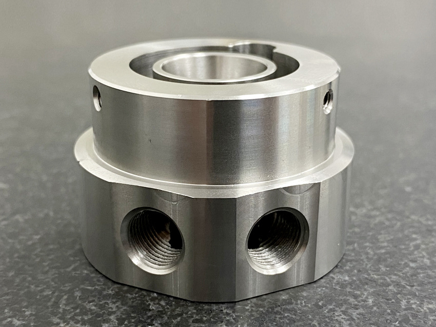
Part geometry should be reviewed before quoting because geometry decides setup count, tool reach, burr location, inspection access, and finishing risk. Deep cavities, thin walls, small corner radii, undercuts, cross holes, long bores, fine threads, and cosmetic faces all change the route. A part may look simple in a 3D model but become difficult when the tool cannot reach a pocket without long stick-out, when a thin wall moves after unclamping, or when an internal burr cannot be inspected directly. A useful engineering scenario is a SUS316 pump housing with cross holes and polished sealing faces. The same part needs corrosion resistance, internal burr control, sealing flatness, and post-polish dimensional checks.
Complex geometries may require more than one machining method. For example, EDM services may be used for features that are difficult to reach with a rotating cutter, followed by CNC grinding services when final geometry, hardness, or surface finish requires a grinding route. This route must still be justified by feature access, material hardness, surface integrity, electrode or wheel access, and inspection needs. A supplier should explain whether the route is chosen for geometry, tolerance, finish, heat-treatment condition, or cost. The buyer should confirm whether alternate radii, reliefs, or datum changes could simplify the route without changing product function.
Consideration 8: Post-Processing and Surface Finishing Options
Post-processing should be selected from function, not appearance alone. Stainless surfaces can be affected by free iron, heat tint, embedded abrasive, burrs, polishing direction, coating thickness, and passivation acceptance. Electropolishing can improve cleanability and reduce micro peaks when allowance, masking, and inspection stage are defined. Passivation helps remove free iron and support the chromium oxide surface, but it does not fix deep scratches, embedded contamination, or poor deburring. ASTM A967 and ASTM A380 are common references for stainless passivation and cleaning, but acceptance still depends on the drawing and service environment.
For parts that require unique visual effects or enhanced surface properties, options such as CNC polishing and PVD coating services should be reviewed with dimensional limits. Polishing can change edge radius, remove material, and reveal waviness if machining marks were not controlled. PVD can improve wear or galling resistance when coating thickness, adhesion, masking, and base finish are suitable. Surface treatment should be checked after machining, not treated as an afterthought. The RFQ should state Ra, grain direction, passivation standard, coating thickness, masked areas, cosmetic class, and whether final dimensions are measured before or after finishing. If coating buildup affects threads or bores, masking or post-finish inspection becomes a production requirement.
Neway’s Professional Stainless Steel CNC Machining Solutions
Neway’s stainless steel CNC machining workflow should connect the eight considerations instead of treating them as separate decisions. During prototyping services, the main goal is usually to validate material behavior, tool access, burr control, surface finish, and inspection assumptions. During mass production services, the same information must be converted into stable tool-life rules, fixture checks, coolant controls, inspection intervals, and post-processing standards. A prototype shortcut should be identified before it becomes a production risk. Buyers should ask which assumptions were validated on the sample and which still need confirmation before repeat production.
Successful stainless steel machining is a connected process chain: grade selection affects tooling, tooling affects heat, heat affects work hardening, workholding affects free-state dimensions, geometry affects burr location, and finishing affects final size and corrosion behavior. Through comprehensive one-stop service, buyers can align material selection, machining process, deburring, surface treatment, and inspection requirements before release. The best next step is to send the drawing, CAD model, stainless grade, quantity, critical features, finishing requirement, and acceptance standard so the machining plan can be reviewed against the real part. That review should state what will be measured, when it will be measured, and which manufacturing assumptions affect cost or delivery.
FAQ
What are the main differences between machining SUS304 and SUS316 stainless steel?
Why is tool life shorter when machining stainless steel, and how can it be improved?
How do I select the most suitable surface treatment for stainless steel parts?
How should burrs and sharp edges be handled after machining stainless steel using CNC?
My product prototype requires machining with stainless steel. Can Neway provide support?