How should burrs and sharp edges be handled after machining stainless steel using CNC?
Burrs and sharp edges on CNC machined stainless steel should be controlled by defining the required edge condition on the drawing, reducing burr formation during machining, selecting a deburring method that fits the geometry, and verifying the final edge before release. Stainless burrs are tougher than many aluminum or carbon-steel burrs because the material is ductile, work-hardens, and can smear instead of breaking away cleanly. Poor edge control can affect assembly fit, sealing, cleaning, operator safety, corrosion resistance, and fatigue-sensitive corners. A buyer should specify edge-break range, no-burr zones, protected datums, cosmetic surfaces, internal intersections, and final inspection method in the RFQ. If the part has medical, aerospace, food, hydraulic, or optical use, the drawing should also define whether “no sharp edge” means visual acceptance, tactile acceptance, measured radius, or no loose burr under magnification.
The Challenge of Stainless Steel Burrs
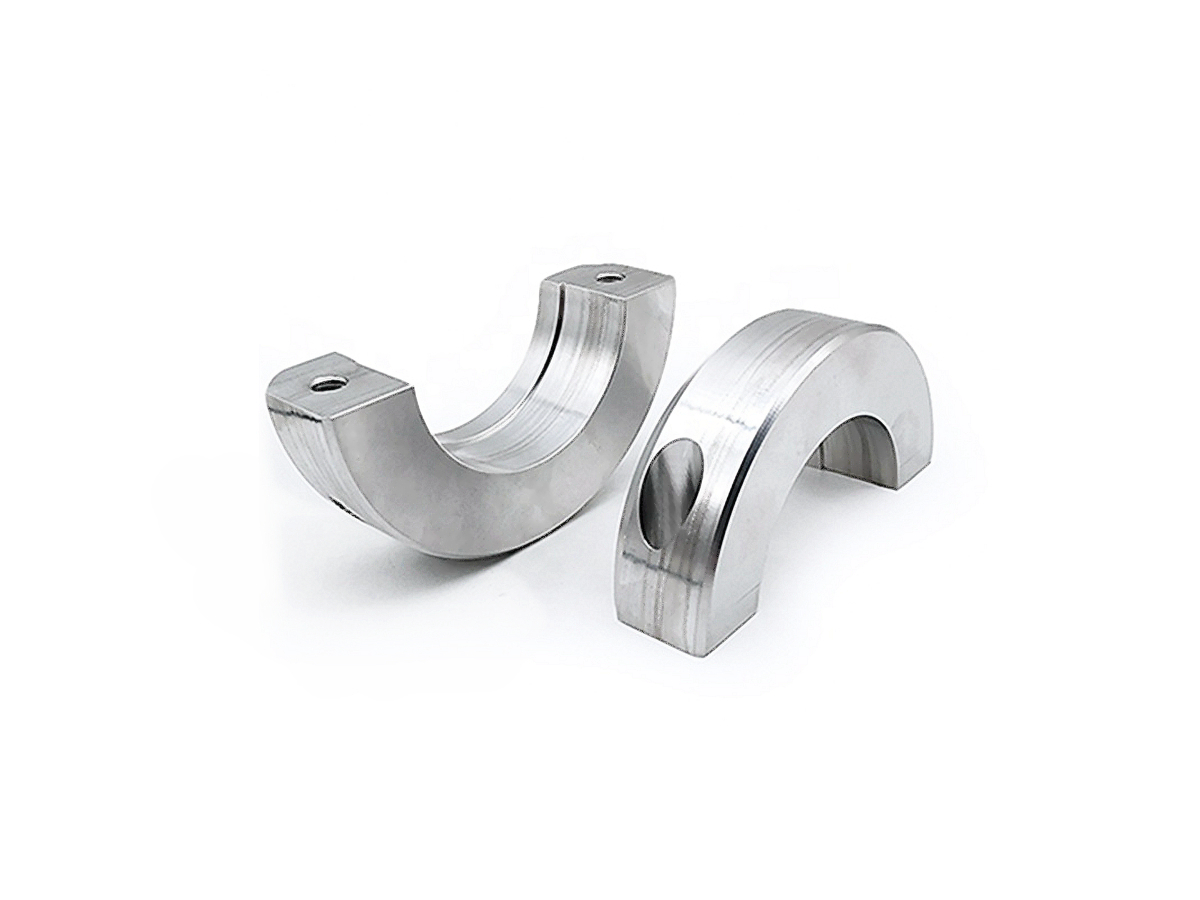
Stainless steel burrs are difficult because they often remain stringy, attached, and work-hardened after CNC Milling or CNC Turning. A milling exit edge, turned groove, cross hole, thread start, or thin wall can develop a sharp lip that looks small but still cuts seals, blocks assembly, traps cleaning fluid, or becomes a corrosion initiation point. If the deburring method only pushes the burr over, the edge may look smooth from one direction while a hardened fold remains attached. Aggressive grinding can also change dimensions, scratch functional faces, embed non-stainless particles, or round a datum edge that should stay sharp. The process should therefore define which edges are broken, which edges are protected, and which burrs require magnified inspection.
Primary Deburring and Edge Radiusing Methods
Manual and Local Mechanical Edge Control
For prototypes, low-volume parts, delicate features, or selective no-burr zones, manual and local mechanical methods offer flexible control when inspection is disciplined.
Hand Deburring Tools: Scrapers, deburring knives, ceramic blades, files, and stones can remove burrs from selected edges without treating every surface the same way. The risk is operator variation, so the drawing should define acceptable edge break, protected surfaces, and inspection sampling.
Abrasive Tools: Die grinders, abrasive cords, sanding sticks, and non-ferrous abrasives can reach grooves, bores, and internal passages. Abrasive media should be compatible with stainless steel to avoid embedded iron and rust staining. This method may be followed by CNC Surface Brushing Treatment when the edge must blend into a controlled satin appearance.
Mechanical Automation for Repeatable Edge Radius
For medium or high-volume stainless parts, automated methods can improve repeatability when the part geometry can tolerate uniform media contact.
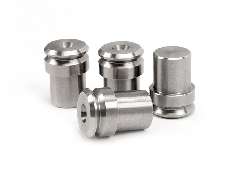
CNC Part Tumbling and Deburring: Vibratory or rotary tumbling uses ceramic, plastic, or synthetic media with a compound suited to stainless steel. It can break exposed edges and remove light burrs on many parts at once. It should be avoided or validated carefully when parts have delicate threads, thin walls, sharp sealing lands, deep blind pockets, or surfaces that must not be rounded.
Thermal Energy Method (TEM): TEM can remove small burrs from cross holes and internal intersections by rapidly oxidizing thin burr material. It needs material and part-specific review because heat exposure, chamber size, cleanliness, and burr size influence results. It is not a substitute for fixing heavy burr formation at the cutting stage.
Electrochemical and Flow-Based Deburring
For high-value parts with internal passages, small cross holes, or surfaces that should avoid mechanical tool marks, electrochemical and flow-based methods may be more suitable.
Electropolishing for Precision Parts: Electropolishing removes a controlled surface layer and can reduce micro-burrs, improve cleanability, and support stainless corrosion resistance. It can also change dimensions, edge radius, and surface appearance, so allowance, masking, Ra target, and inspection stage must be defined before use.
Abrasive Flow Machining (AFM): AFM pushes an abrasive polymer medium through passages or across edges to radius difficult internal features. It is useful for intersecting drilled holes, manifolds, and hydraulic or medical flow paths, but media size, pressure, cycle count, and cleaning must be validated on representative parts.
Engineering Guidelines for Effective Burr Management
Design for Deburring: Put the edge requirement on the drawing, such as “break sharp edges 0.1–0.2 mm unless otherwise specified,” only when that range fits the feature size, sealing face, and tolerance stack. Mark critical edges separately.
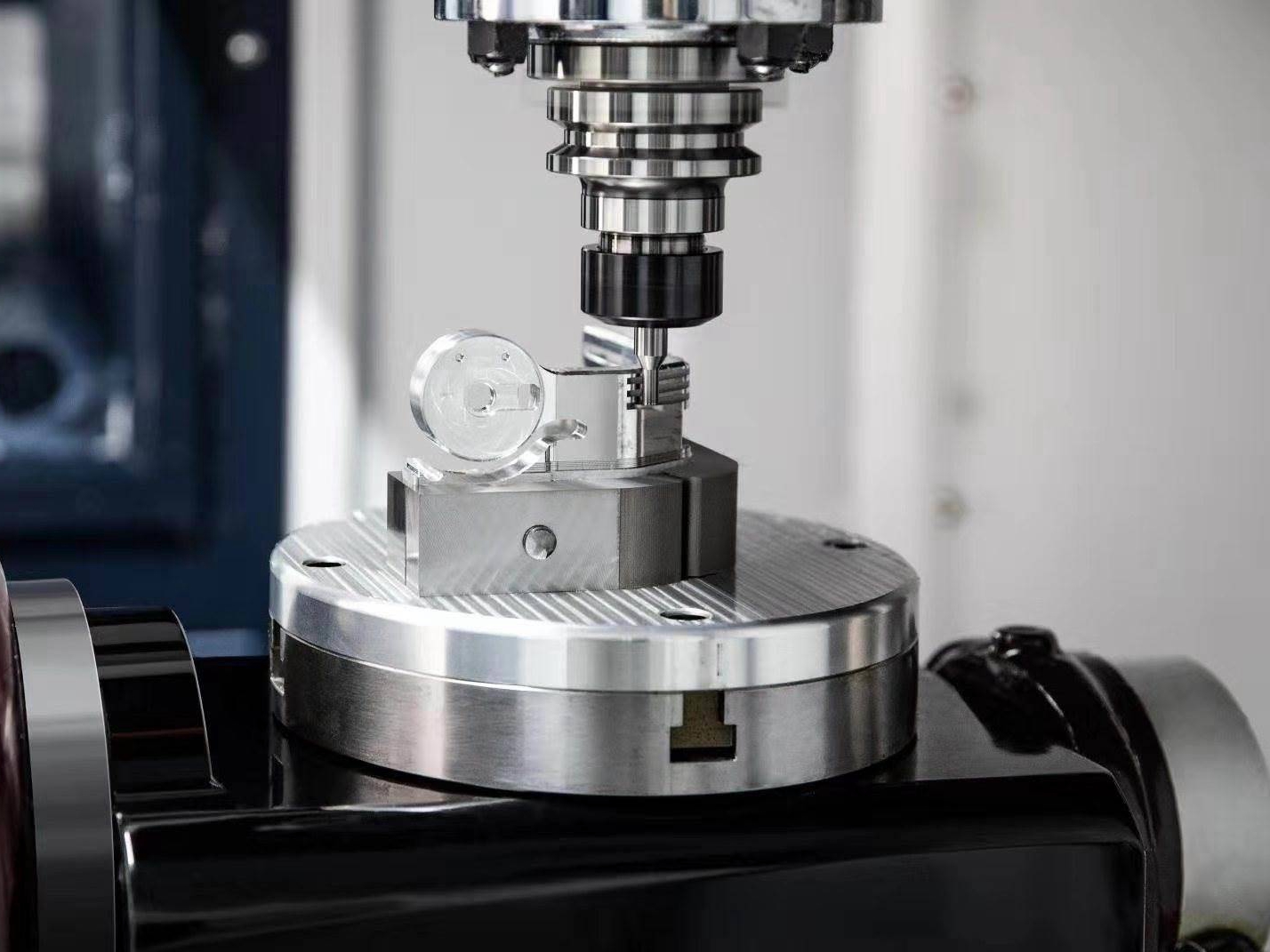
Optimize CNC Machining Strategies: Reduce burrs at the source with sharp tools, stable feeds and speeds, climb milling where suitable, exit-path control, and correct tool wear limits during the CNC Machining Process.
Select the Right Combination: Use a sequence when one method cannot meet all requirements. Tumbling may handle exposed edges, manual deburring may protect critical datums, and electropolishing may finish micro-burrs after dimensions are confirmed.
Validate and Inspect: Use tactile checks, visual standards, optical magnification, borescopes, edge-radius gauges, or microscopic review when required. Parts for Medical Device or Aerospace and Aviation use may need documented sampling, no-loose-burr evidence, and final inspection after cleaning or surface treatment. The inspection plan should state sample size, acceptance tool, lighting or magnification condition, and whether cosmetic defects are judged before or after passivation, brushing, or electropolishing.