Why is tool life shorter when machining stainless steel, and how can it be improved?
From an engineering and machining standpoint, tool life is significantly challenged when processing stainless steel due to a combination of the material's inherent physical properties and the severe thermomechanical loads imposed during cutting. The primary culprits are its high work hardening rate, low thermal conductivity, high toughness, and the presence of hard abrasive carbides. However, through a systematic approach to tool selection, geometry, and process parameters, substantial improvements in tool life and machining efficiency can be achieved.
The Root Causes of Short Tool Life
The fundamental issue lies in the metallurgy of stainless steels. Their austenitic structure, essential for corrosion resistance, leads to a pronounced work hardening effect. As the tool shears the material, the localized stress induces a phase transformation that hardens the surface ahead of and behind the cut. This continuously work-hardened surface aggressively abrades the tool's flank and rake face. Furthermore, stainless steel's thermal conductivity is typically only about one-third that of carbon steel. This inability to dissipate heat efficiently leads to the concentration of extremely high temperatures (often exceeding 1000°C) at the tool-workpiece interface, accelerating thermal softening, diffusion wear, and notch wear.
This is compounded by the material's ductility and toughness, which lead to the formation of long, continuous chips. These chips can weld onto the cutting edge (built-up edge), which eventually breaks off, taking fragments of the tool coating with it. For materials like Stainless Steel SUS304 or SUS316, these challenges are paramount. When machining even tougher materials like Inconel 718, these effects are magnified, requiring even more specialized strategies.
Strategies for Improving Tool Life and Machining Performance
1. Optimal Tool Material and Coating Selection
The first line of defense is selecting a tool substrate and coating that can withstand high temperatures and abrasion. Uncoated or standard-coated tools are unsuitable. Instead, premium sub-micrograin or ultrafine-grain carbide substrates with high fracture toughness are essential. These should be paired with advanced physical vapor deposition (PVD) coatings such as TiAlN (Titanium Aluminum Nitride) or AlCrN (Aluminum Chromium Nitride). These coatings provide a hard, thermally stable barrier that reduces abrasive wear and reflects heat into the chip. For severe applications, ceramic or CBN (Cubic Boron Nitride) tools may be considered, though they require very rigid setups.
2. Strategic Tool Geometry and Edge Preparation
Tool geometry is crucial for minimizing cutting forces and effectively managing chips. A positive rake angle is highly recommended to shear the material cleanly with less force, minimizing work hardening. A sharp, honed cutting edge is vital, but for heavier roughing operations, a slight T-land (chamfer) or a small hone can prevent micro-chipping. Crucially, the tool must have sharp, polished flute geometries in milling, or defined chip breaker forms in turning, to ensure tight, controlled chip curl that evacuates heat efficiently. This prevents chips from recutting or welding to the tool, a common failure mode.
3. Rigorous Application of Cutting Parameters
Parameter selection must actively combat the material's tendencies. Contrary to intuition, running at too low a speed can be more detrimental than running too high, as it promotes work hardening by dwelling in the cut. Maintaining a sufficiently high surface speed is necessary to generate the thermal energy needed for effective shearing. However, this must be balanced against heat generation.
The most critical parameter is feed rate. It is imperative to maintain a high enough feed per tooth to ensure the cut is made below the work-hardened surface from the previous pass. "Babying" the tool with too light a feed guarantees rapid failure by exclusively cutting the hardened layer. A consistent, engaged cut is far superior to an intermittent, light one.
4. Advanced Coolant and Lubrication Strategies
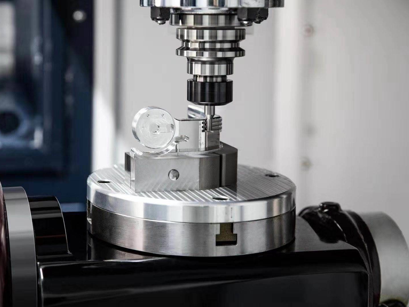
Given the low thermal conductivity, effective heat removal is non-negotiable. For most CNC Milling Service and CNC Turning Service operations on stainless steel, a high-pressure, high-volume flood coolant is standard. The coolant not only reduces temperature but also aids in chip evacuation. For particularly tough grades or deep-hole operations like those in CNC Drilling Service, through-tool coolant is exceptionally effective, delivering lubricant directly to the cutting interface and breaking chips into manageable pieces. In some cases, specialized neat oils or minimum quantity lubrication (MQL) with EP (Extreme Pressure) additives can provide superior lubrication, reducing friction and built-up edge.
5. Ensuring System Rigidity and Stability
Any vibration or chatter exponentially accelerates tool failure in stainless steel due to its tendency to work harden. A rigid machine tool, solid workholding, and short, stout tool holders are paramount. This minimizes deflection, allows for more aggressive machining parameters, and promotes a consistent, predictable tool wear pattern rather than catastrophic chipping.